EP0965725B1 - End of travel detecting device for a bidirectionally mobile element, especially roller shutter drum, and driving device of bidirectionally mobile element equipped with such end of travel device - Google Patents
End of travel detecting device for a bidirectionally mobile element, especially roller shutter drum, and driving device of bidirectionally mobile element equipped with such end of travel device Download PDFInfo
- Publication number
- EP0965725B1 EP0965725B1 EP99490017A EP99490017A EP0965725B1 EP 0965725 B1 EP0965725 B1 EP 0965725B1 EP 99490017 A EP99490017 A EP 99490017A EP 99490017 A EP99490017 A EP 99490017A EP 0965725 B1 EP0965725 B1 EP 0965725B1
- Authority
- EP
- European Patent Office
- Prior art keywords
- limit switch
- mobile element
- processing means
- mode
- motorised
- Prior art date
- Legal status (The legal status is an assumption and is not a legal conclusion. Google has not performed a legal analysis and makes no representation as to the accuracy of the status listed.)
- Expired - Lifetime
Links
Images
Classifications
-
- H—ELECTRICITY
- H02—GENERATION; CONVERSION OR DISTRIBUTION OF ELECTRIC POWER
- H02P—CONTROL OR REGULATION OF ELECTRIC MOTORS, ELECTRIC GENERATORS OR DYNAMO-ELECTRIC CONVERTERS; CONTROLLING TRANSFORMERS, REACTORS OR CHOKE COILS
- H02P25/00—Arrangements or methods for the control of AC motors characterised by the kind of AC motor or by structural details
- H02P25/02—Arrangements or methods for the control of AC motors characterised by the kind of AC motor or by structural details characterised by the kind of motor
- H02P25/04—Single phase motors, e.g. capacitor motors
-
- E—FIXED CONSTRUCTIONS
- E06—DOORS, WINDOWS, SHUTTERS, OR ROLLER BLINDS IN GENERAL; LADDERS
- E06B—FIXED OR MOVABLE CLOSURES FOR OPENINGS IN BUILDINGS, VEHICLES, FENCES OR LIKE ENCLOSURES IN GENERAL, e.g. DOORS, WINDOWS, BLINDS, GATES
- E06B9/00—Screening or protective devices for wall or similar openings, with or without operating or securing mechanisms; Closures of similar construction
- E06B9/56—Operating, guiding or securing devices or arrangements for roll-type closures; Spring drums; Tape drums; Counterweighting arrangements therefor
- E06B9/80—Safety measures against dropping or unauthorised opening; Braking or immobilising devices; Devices for limiting unrolling
- E06B9/82—Safety measures against dropping or unauthorised opening; Braking or immobilising devices; Devices for limiting unrolling automatic
- E06B9/88—Safety measures against dropping or unauthorised opening; Braking or immobilising devices; Devices for limiting unrolling automatic for limiting unrolling
-
- H—ELECTRICITY
- H02—GENERATION; CONVERSION OR DISTRIBUTION OF ELECTRIC POWER
- H02P—CONTROL OR REGULATION OF ELECTRIC MOTORS, ELECTRIC GENERATORS OR DYNAMO-ELECTRIC CONVERTERS; CONTROLLING TRANSFORMERS, REACTORS OR CHOKE COILS
- H02P23/00—Arrangements or methods for the control of AC motors characterised by a control method other than vector control
- H02P23/24—Controlling the direction, e.g. clockwise or counterclockwise
-
- E—FIXED CONSTRUCTIONS
- E06—DOORS, WINDOWS, SHUTTERS, OR ROLLER BLINDS IN GENERAL; LADDERS
- E06B—FIXED OR MOVABLE CLOSURES FOR OPENINGS IN BUILDINGS, VEHICLES, FENCES OR LIKE ENCLOSURES IN GENERAL, e.g. DOORS, WINDOWS, BLINDS, GATES
- E06B9/00—Screening or protective devices for wall or similar openings, with or without operating or securing mechanisms; Closures of similar construction
- E06B9/56—Operating, guiding or securing devices or arrangements for roll-type closures; Spring drums; Tape drums; Counterweighting arrangements therefor
- E06B9/68—Operating devices or mechanisms, e.g. with electric drive
- E06B2009/6809—Control
- E06B2009/6872—Control using counters to determine shutter position
Definitions
- the present invention relates to an end detection device stroke of a bi-directionally movable member, in particular a drum roller shutter, provided with means for adjusting and recording its positions limit switch, as well as a device for driving a bi-directionally movable member equipped with such a limit switch detection device.
- the invention may also be used in all areas of economic activity in which we want limit the travel of a bi-directionally movable member between two points.
- Means for comparing the position of the drum with the saved end positions then allow the detection of positions in which the movements of the drum must be blocked.
- a first drawback of such mechanical assemblies is that they are located at the level of the drum and therefore require difficult interventions. Indeed, the roller shutter drums are generally hidden in a chest placed in height and the adjustment of the ends must be run blind.
- the logic processing unit has two switches ensuring both the selection of the engine operating mode, the initialization in programming mode and limit switch programming.
- the transition to programming mode is initiated when the two switches are closed.
- the motor is then switched off.
- ULT waits for the operator by switching one of the two command switches the engine to run.
- the switching of the two switches in the closed position, for a time given means to the ULT the new position of the limit switches.
- the programming sequence is heavy and requires engine shutdown for time periods. It forces the operator to immobilize the engine for the first time during the phase initialization in programming mode, and a second time for at least one determined time, to signify to the system the new end position of race.
- the purpose of the present invention is to provide a device for end of stroke detection which overcomes the aforementioned drawbacks and allows make adjustments to their position remotely.
- Another object of the present invention is to provide a limit switch detection device which reduces the risk of malfunctionning.
- Another object of the present invention is to provide a end-of-travel detection device which can be adjusted by real visualization of the positions in which one wishes to block the organ mobile concerned.
- the present invention relates to an end detection device stroke of a bi-directionally movable member, in particular a drum roller shutter, provided with means for adjusting and recording its positions limit switch, said device comprising motor means drive of the movable member, means for controlling the position of the movable member, means for comparing said position of the member mobile with the saved end positions, and digital processing means capable of operate in two different modes, one says "normal”, the other says “Setting”, said control means being provided capable of giving a image of the position of the organ in the form of a digitized input signal processing means, and said adjusting means comprising means electrics for selecting the mode of use of the processing means and end positions for their storage, said selection means being provided suitable for allowing the adjustment of the end-of-travel positions at the stolen, while the movable member is actuated, without stopping the motor means for timeout periods.
- the invention also relates to a drive device a bi-directionally movable member equipped with a device for detecting limit switch as described above.
- the present invention relates to an end detection device stroke of a bi-directionally movable member, in particular drum roller shutter, provided with means for adjusting and recording its positions limit switch.
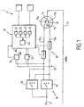
- the limit switch detection device comprises means 1 for controlling the position of the movable member and means for comparing said position of the member mobile with the saved end positions.
- digital processing means 30 capable of operating according to two different modes, one says "normal” and the other says “setting”.
- the first authorizes, for example, the tracking and blocking of the movable member when it arrives at the level of the limit positions saved while the second authorizes, in particular, the adjustment and / or modification thereof.
- control means are provided capable of give an image of the position of the organ in the form of a digitized signal at the input of said processing means 30.
- control means are, for example, means for counting pulses delivered by cooperating magnetic sensors with a magnetic field, mobile in relation to said organ.
- the means for adjusting the position of the end of race include electrical means 18,20; 18, 40 selection of mode of use of the processing means 30, said electrical means being further provided capable of authorizing the selection of the end positions of race for their memorization, when the movable member has arrived at the position desired.
- a digitized signal for tracking the positions of the mobile organ, digital processing means and means of electrical selection thus allows, for example, the realization of electrical wiring, allowing remote adjustment of end positions race and facilitating operator interventions.
- Said processing means 30 are provided capable of producing, for example, counting functions from the signal giving the image of the position of the organ. They are provided for this, in particular, with one or more counters 32.
- Said processing means 30 also allow, by example, comparing the value of the counter (s) 32 with a value corresponding to the end-of-travel positions, these being provided for stored, in particular, in a memory module 33.
- Said processing means 30 also allow, by example, storing the limit values set in said module memory 33 and / or the issuance of a blocking order of the movable member in the event of correspondence between the values appearing in the counter (s) 32 and those stored in a memory module 33.
- Said processing means 30 are further provided suitable, for example, to authorize a switching of their operation between the “normal” mode and “setting” mode, in particular using data input established from the electrical current also allowing the setting movement of the mobile organ.
- said processing means 30 carry out so, for example, counting functions, comparison of values counted with the limit values, and issuance of blocking order in match, while in "setting” mode, the comparison of the values counted with the limit values is possibly inhibited and replaced by the news storage function limit values set.
- said processing means 30 take into account counts, for example, the signal or signals giving the image of the position of the mobile organ and / or the signal or signals determining their mode of operation. On exit, they issue, for example, blocking orders of said movable member.
- Said processing means 30 comprise, for example, a microprocessor 34 capable of implementing software allowing the realization, in particular, of said counting functions, comparison, storage, switching and / or blocking order transmission.
- Said counters 32 consist, for example, of a mobile unit position counter, a limit switch and / or of a time counter.
- said selection means 18, 20; 18, 40 are provided suitable for allowing the adjustment of the end-of-travel positions at the fly, that is to say during the actual movement of the movable member.
- the stored values then correspond, for example, to the value of counter 32 after stopping said movable member at the position to be saved as end position.
- the present invention also relates to a device for driving a bi-directionally movable member equipped with a such end of stroke detection device.
- Said drive device comprises, for example, motor means 10 for driving the movable member and / or means for selection 16 of the operating mode of said motor means 10.
- Said means 16 for selecting the operating mode said motor means 10 allow an operator to choose, for example, the direction of movement of said movable member and / or keeping it stationary.
- said processing means 30 are connected by mounting in bypass on a supply line 35 provided between said motor means 10 and said means 16 for selecting the operating mode of said motor means 10.
- Said means 16 for selecting the operating mode said motor means 10 are, for example, connected to the network, marked 17, and are optionally provided capable of isolating said supply line 35 from this one. This prevents said means 1 for controlling and / or processing 30 are permanently powered. Furthermore, such a provision allows, if desired, to control multiple motors from one control point unique.
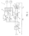
- said supply line 35 consists, for example, of two cables 12a, 12b each allowing, for example, the supply of said motor means 10 for operation in a given direction and said means 18, 20; 18, 40 for selecting the operating mode of the processing means 30 digital and end positions consist of means of setting under simultaneous tension of said two cables 12a, 12b.
- Said simultaneous energization is planned to be temporary. It ceases, for example, when the movable member has arrived at the desired position to define an end position.
- said setting means under simultaneous tension of said two cables 12a, 12b comprise a push button 40 able to close a short circuit line 41 provided between said two cables 12a, 12b.
- This first embodiment of the setting means under simultaneous tension of the two cables 12a, 12b is illustrated in FIG. 2.
- a tool 20, 40 distinct from the tool 18 for controlling the direction of rotation of the motor, to switch from the mode "Normal” in "programming mode".
- Said motor means 10 consist, in particular, of a motor having, for example, two windings 11a, 11b allowing each rotation in a given direction.
- Said windings 11a, 11b are provided, in particular, between one of the cables 12a, 12b, forming a phase line and a neutral line 13, possibly connected to a common point 14 provided between the said windings 11a, 11b.
- a capacity 15 is, for example, provided at the level of said windings 11a, 11b between their terminals opposite the common point 14.
- Said drive device further comprises, by example, blocking means 19 of said motor means 10. They are consisting, in particular, of a circuit breaker member provided on each of the cables 12a, 12b.
- Said means 16 for selecting the operating mode said motor means 10 and / or said selection means 18, 20; 18, 40 from operating mode of the processing means 30 and the end positions limit switches consist, for example, of a three-position switch. This is located, in particular, between sector 17 and said supply line 35.
- Said switch could be constituted, for example, for said means 16 for selecting the operating mode of the means motor 10, of a direction reversing button 18, and for said means of the mode of selection of the processing means 30, of a button inverter 20.
- one of the terminals corresponds to a direction of movement of the movable member, the second to the other direction of movement of this and the third at the stop of the engine means.
- a first of the terminals corresponds to the mode for setting a first end position, a second to the setting mode of the second end position and the third terminal in normal operating mode.
- the operator actuates the inverter 18 to connect the phase line 12a with the sector and allow the displacement of the movable member in the direction concerned. Simultaneously, the other phase line 12b is cut at using the circuit breaker 19 provided thereon, as in normal mode.
- the processing means 30 being connected in bypass to said phase lines 12a, 12b, they then note the appearance at the input of a state different from the normal state, each of said lines 12a, 12b being supplied, instead of just one, upstream of the locking means 19.
- the mode limit switch is activated, motor in rotation.
- Said drive device further comprises, possibly to promote the functioning of said processing means 30, a stabilized supply 36 between them and said supply line 35.
- processing means digital 30 It also includes, possibly, means 37 for analog / digital conversion provided between said processing means digital 30 and said selection means 18, 20; 18, 40 of the operation of said processing means 30.
- Said means of conversion include, among others, a voltage divider, a rectifier and / or a filter.
Description
La présente invention concerne un dispositif de détection de fin de course d'un organe mobile bi-directionnellement, notamment tambour de volet roulant, muni de moyens de réglage et d'enregistrement de ses positions de fin de course, ainsi qu'un dispositif d'entraínement d'un organe mobile bi-directionnellement équipé d'un tel dispositif de détection de fin de course.The present invention relates to an end detection device stroke of a bi-directionally movable member, in particular a drum roller shutter, provided with means for adjusting and recording its positions limit switch, as well as a device for driving a bi-directionally movable member equipped with such a limit switch detection device.
Bien que plus particulièrement prévue pour des applications dans le domaine des volets roulants, l'invention pourra également être utilisée dans tous les domaines de l'activité économique dans lesquels on souhaite limiter entre deux points la course d'un organe mobile bi-directionnellement.Although more specifically intended for applications in the field of roller shutters, the invention may also be used in all areas of economic activity in which we want limit the travel of a bi-directionally movable member between two points.
Actuellement, dans le domaine des volets roulants, on connaít différents dispositifs de détection de fin de course du tambour d'entraínement du tablier du volet roulant.Currently, in the field of roller shutters, we know different end of stroke detection devices for the drive drum of the roller shutter deck.
Ils sont constitués, par exemple, de moyens de contrôle mécanique tels que des jeux de réducteur à engrenages entraínés par le tambour du volet roulant et permettant de suivre la trajectoire de celui-ci.They consist, for example, of means of control mechanical such as gear reducer sets driven by the roller shutter drum and allowing to follow its trajectory.
Des moyens de comparaison de la position du tambour avec les positions de fin de course enregistrées autorisent alors la détection des positions dans lesquelles les mouvements du tambour doivent être bloqués.Means for comparing the position of the drum with the saved end positions then allow the detection of positions in which the movements of the drum must be blocked.
Cela étant, lors de la mise en place du volet roulant, ou à tout moment ultérieur, il peut être nécessaire de régler les positions de fin de course et on connaít également différentes solutions permettant d'intervenir en ce sens.However, when installing the roller shutter, or at all later it may be necessary to adjust the end positions and we also know different solutions to intervene in this meaning.
Toutefois, il s'agit généralement de montages mécaniques complexes, utilisant le déplacement de pièces mobiles les unes par rapport aux autres pour sélectionner les conditions selon lesquelles des moyens mécaniques de blocage de la rotation du tambour pourront être actionnés.However, these are generally mechanical assemblies complex, using the displacement of moving parts in relation to others to select the conditions under which means mechanical blocking of the rotation of the drum can be activated.
Un premier inconvénient de tels montages mécaniques est qu'ils sont situés au niveau du tambour et nécessitent en conséquence des interventions difficiles. En effet, les tambours de volets roulants sont généralement dissimulés dans un coffre placé en hauteur et le réglage des fins de course doit être effectué en aveugle. A first drawback of such mechanical assemblies is that they are located at the level of the drum and therefore require difficult interventions. Indeed, the roller shutter drums are generally hidden in a chest placed in height and the adjustment of the ends must be run blind.
Un autre inconvénient est qu'ils rendent parfois nécessaire l'intervention des deux opérateurs.Another disadvantage is that they sometimes make it necessary the intervention of the two operators.
Il est également à noter que l'utilisateur de pièces mécaniques peut signifier une augmentation des risques de casse ou d'usure des moyens employés.It should also be noted that the user of mechanical parts may mean increased risk of breakage or wear and tear employees.
On connaít le document EP-A-0.822.315 concernant un dispositif de commande d'un moteur permettant la détection et la mémorisation des fins de course d'un organe mobile.We know the document EP-A-0.822.315 concerning a device motor control for detecting and storing ends of a movable member.
L'unité logique de traitement présente deux commutateurs assurant à la fois la sélection du mode de marche du moteur, l'initialisation en mode de programmation et la programmation des fins de course.The logic processing unit has two switches ensuring both the selection of the engine operating mode, the initialization in programming mode and limit switch programming.
Le passage en mode de programmation est initié lorsque les deux commutateurs sont fermés. Le moteur est alors mis hors tension. L'ULT attend que l'opérateur en commutant l'un des deux commutateurs commande au moteur de tourner. Lorsque l'organe mobile arrive en fin de course désiré, le basculement des deux commutateurs en position fermée, pendant un temps donné, signifie à l'ULT la nouvelle position des fins de course.The transition to programming mode is initiated when the two switches are closed. The motor is then switched off. ULT waits for the operator by switching one of the two command switches the engine to run. When the movable member reaches the desired end of travel, the switching of the two switches in the closed position, for a time given, means to the ULT the new position of the limit switches.
. Néanmoins, la séquence de programmation est lourde et nécessite l'arrêt du moteur pour des périodes de temporisation. Elle oblige l'opérateur à immobiliser le moteur une première fois lors de la phase d'initialisation en mode programmation, et une deuxième fois pour au moins un temps déterminé, pour signifier au système la nouvelle position de fin de course.. However, the programming sequence is heavy and requires engine shutdown for time periods. It forces the operator to immobilize the engine for the first time during the phase initialization in programming mode, and a second time for at least one determined time, to signify to the system the new end position of race.
On connaít de même le document EP-A-0.770.757 et le document FR-A-2.525.832 permettant de régler la position des fins de course et dont l'ULT fonctionne dans un mode dit normal et dans un mode de programmation des fins de course.We also know the document EP-A-0.770.757 and the document FR-A-2.525.832 for adjusting the position of the limit switches and whose ULT operates in a so-called normal mode and in a programming of limit switches.
Néanmoins, tout comme le document EP-A-0.822.315, le passage du mode normal en mode de programmation ne peut être effectué sans provoquer l'arrêt du moteur.However, like document EP-A-0.822.315, the switching from normal mode to programming mode cannot be performed without stopping the engine.
Le but de la présente invention est de proposer un dispositif de détection de fin de course qui pallie les inconvénients précités et permette de réaliser des réglages de leur position à distance.The purpose of the present invention is to provide a device for end of stroke detection which overcomes the aforementioned drawbacks and allows make adjustments to their position remotely.
Un autre but de la présente invention est de proposer un dispositif de détection de fin de course qui permette de réduire les risques de mauvais fonctionnement.Another object of the present invention is to provide a limit switch detection device which reduces the risk of malfunctionning.
Un autre but de la présente invention est de proposer un dispositif de détection de fin de course dont le réglage puisse être effectué par visualisation réelle des positions dans lesquelles on souhaite bloquer l'organe mobile concerné.Another object of the present invention is to provide a end-of-travel detection device which can be adjusted by real visualization of the positions in which one wishes to block the organ mobile concerned.
D'autres buts et avantages de l'invention apparaítront au cours de la description qui va suivre qui n'est donnée qu'à titre indicatif et qui n'a pas pour but de la limiter.Other objects and advantages of the invention will become apparent during of the description which follows which is given for information only and which has not to limit it.
La présente invention concerne un dispositif de détection de fin de course d'un organe mobile bi-directionnellement, notamment tambour de volet roulant, muni de moyens de réglage et d'enregistrement de ses positions de fin de course, ledit dispositif comprenant des moyens moteur d'entraínement de l'organe mobile, des moyens de contrôle de la position de l'organe mobile, des moyens de comparaison de ladite position de l'organe mobile avec les positions de fin de cours enregistrées, et des moyens de traitement numériques aptes à fonctionner selon deux modes différents, l'un dit « normal », l'autre dit de « réglage », lesdits moyens de contrôle étant prévus aptes à donner une image de la position de l'organe sous la forme d'un signal numérisé en entrée des moyens de traitement, et lesdits moyens de réglage comprenant des moyens électriques de sélection du mode d'utilisation des moyens de traitement et des positions de fin de course pour leur mémorisation, lesdits moyens de sélection étant prévus aptes à permettre le réglage des positions de fin de course à la volée, alors que l'organe mobile est actionné, sans arrêt des moyens moteur pour des périodes de temporisation.The present invention relates to an end detection device stroke of a bi-directionally movable member, in particular a drum roller shutter, provided with means for adjusting and recording its positions limit switch, said device comprising motor means drive of the movable member, means for controlling the position of the movable member, means for comparing said position of the member mobile with the saved end positions, and digital processing means capable of operate in two different modes, one says "normal", the other says "Setting", said control means being provided capable of giving a image of the position of the organ in the form of a digitized input signal processing means, and said adjusting means comprising means electrics for selecting the mode of use of the processing means and end positions for their storage, said selection means being provided suitable for allowing the adjustment of the end-of-travel positions at the stolen, while the movable member is actuated, without stopping the motor means for timeout periods.
L'invention concerne également un dispositif d'entraínement d'un organe mobile bi-directionnellement équipé d'un dispositif de détection de fin de course tel que décrit ci-dessus.The invention also relates to a drive device a bi-directionally movable member equipped with a device for detecting limit switch as described above.
L'invention sera mieux comprise à la lecture de la description suivante, accompagnée des deux dessins en annexe qui illustrent respectivement, sous une forme schématique, un premier et un second exemples du dispositif de détection de fin de course conforme à l'invention.The invention will be better understood on reading the description following, accompanied by the two annexed drawings which illustrate respectively, in schematic form, a first and a second examples of the limit switch detection device according to the invention.
La présente invention concerne un dispositif de détection de fin de course d'un organe mobile bi-directionnellement notamment tambour de volet roulant, muni de moyens de réglage et d'enregistrement de ses positions de fin de course.The present invention relates to an end detection device stroke of a bi-directionally movable member, in particular drum roller shutter, provided with means for adjusting and recording its positions limit switch.
Bien que plus particulièrement prévue pour des applications dans le domaine des volets roulants, elle pourra également être utilisée dans tous les secteurs de l'activité économique dans lesquels on souhaite limiter entre deux points la course d'un organe mobile bi-directionnellement.Although more specifically intended for applications in the field of roller shutters, it can also be used in all sectors of economic activity in which we wish to limit between two points the stroke of a bi-directionally movable member.
Comme illustré, le dispositif de détection de fin de course conforme à l'invention comprend des moyens 1 de contrôle de la position de l'organe mobile et des moyens de comparaison de ladite position de l'organe mobile avec les positions de fin de course enregistrées.As illustrated, the limit switch detection device according to the invention comprises means 1 for controlling the position of the movable member and means for comparing said position of the member mobile with the saved end positions.
Il comprend également, pour permettre le réglage desdites positions, des moyens de traitement numérique 30, aptes à fonctionner selon deux modes différents, l'un dit « normal » et l'autre dit de « réglage ». Le premier autorise, par exemple, le suivi et le blocage de l'organe mobile lorsqu'il arrive au niveau des positions de fin de course enregistrées tandis que le second autorise, notamment, le réglage et/ou la modification de celles-ci.It also includes, to allow the adjustment of said positions, digital processing means 30, capable of operating according to two different modes, one says "normal" and the other says "setting". The first authorizes, for example, the tracking and blocking of the movable member when it arrives at the level of the limit positions saved while the second authorizes, in particular, the adjustment and / or modification thereof.
Par ailleurs, lesdits moyens de contrôle sont prévus aptes à donner une image de la position de l'organe sous la forme d'un signal numérisé en entrée desdits moyens de traitement 30. Il s'agit, par exemple, de moyens de comptage d'impulsions délivrées par des capteurs magnétiques coopérant avec un champ magnétique, mobile en relation avec ledit organe.Furthermore, said control means are provided capable of give an image of the position of the organ in the form of a digitized signal at the input of said processing means 30. These are, for example, means for counting pulses delivered by cooperating magnetic sensors with a magnetic field, mobile in relation to said organ.
Quant aux moyens de réglage de la position des fins de
course, ils comprennent des moyens électriques 18,20 ; 18, 40 de sélection du
mode d'utilisation des moyens de traitement 30, lesdits moyens électriques
étant en outre prévus aptes à autoriser la sélection des positions de fin de
course pour leur mémorisation, lorsque l'organe mobile est arrivé à la position
désirée.As for the means for adjusting the position of the end of
race, they include
L'utilisation d'un signal numérisé pour le suivi des positions de l'organe mobile, de moyens numériques de traitement et de moyens de sélection de nature électrique permet ainsi, par exemple, la réalisation de câblages électriques, autorisant le réglage à distance des positions de fin de course et facilitant les interventions des opérateurs.The use of a digitized signal for tracking the positions of the mobile organ, digital processing means and means of electrical selection thus allows, for example, the realization of electrical wiring, allowing remote adjustment of end positions race and facilitating operator interventions.
Lesdits moyens de traitement 30 sont prévus aptes à réaliser,
par exemple, des fonctions de comptage à partir du signal donnant l'image de
la position de l'organe. Ils sont munis pour cela, notamment, d'un ou plusieurs
compteurs 32.Said processing means 30 are provided capable of producing,
for example, counting functions from the signal giving the image of
the position of the organ. They are provided for this, in particular, with one or
Lesdits moyens de traitement 30 permettent également, par
exemple, la comparaison de la valeur du ou des compteurs 32 avec une valeur
correspondant aux positions de fin de course, celles-ci étant prévues stockées,
notamment, dans un module mémoire 33.Said processing means 30 also allow, by
example, comparing the value of the counter (s) 32 with a value
corresponding to the end-of-travel positions, these being provided for stored,
in particular, in a
Lesdits moyens de traitement 30 permettent encore, par
exemple, le stockage des valeurs de fin de course réglées dans ledit module
mémoire 33 et/ou l'émission d'ordre de blocage de l'organe mobile en cas de
correspondance entre les valeurs figurant dans le ou les compteurs 32 et celles
stockées dans un module mémoire 33.Said processing means 30 also allow, by
example, storing the limit values set in said
Lesdits moyens de traitement 30 sont en outre prévus aptes, par exemple, à autoriser une commutation de leur fonctionnement entre le mode « normal » et le mode « réglage », notamment en utilisant des données d'entrée établies à partir du courant électrique permettant également la mise en mouvement de l'organe mobile.Said processing means 30 are further provided suitable, for example, to authorize a switching of their operation between the “normal” mode and “setting” mode, in particular using data input established from the electrical current also allowing the setting movement of the mobile organ.
En mode « normal », lesdits moyens de traitement 30 réalisent ainsi, par exemple, les fonctions de comptage, comparaison des valeurs comptées avec les valeurs de fin de course, et émission d'ordre de blocage en cas de correspondance, tandis qu'en mode « réglage », la fonction de comparaison des valeurs comptées avec les valeurs de fin de course est éventuellement inhibée et remplacée par la fonction de stockage des nouvelles valeurs de fin de course réglées.In “normal” mode, said processing means 30 carry out so, for example, counting functions, comparison of values counted with the limit values, and issuance of blocking order in match, while in "setting" mode, the comparison of the values counted with the limit values is possibly inhibited and replaced by the news storage function limit values set.
Ainsi, en entrée, lesdits moyens de traitement 30 prennent en compte, par exemple, le ou les signaux donnant l'image de la position de l'organe mobile et/ou le ou les signaux déterminant leur mode de fonctionnement. En sortie, ils émettent, par exemple, les ordres de blocage dudit organe mobile.Thus, at input, said processing means 30 take into account counts, for example, the signal or signals giving the image of the position of the mobile organ and / or the signal or signals determining their mode of operation. On exit, they issue, for example, blocking orders of said movable member.
Lesdits moyens de traitement 30 comprennent, par exemple,
un microprocesseur 34 apte à mettre en oeuvre un logiciel permettant la
réalisation, notamment, desdites fonctions de comptage, comparaison,
stockage, commutation et/ou d'émission d'ordre de blocage.Said processing means 30 comprise, for example,
a
Lesdits compteurs 32 sont constitués, par exemple, d'un
compteur de position de l'organe mobile, d'un compteur de fin de course et/ou
d'un compteur de temps.Said
Afin d'éviter le réglage des positions de fin de course par une
indication brute et théorique des valeurs de compteur 32 pour lesquelles
l'organe mobile doit être bloqué, lesdits moyens de sélection 18, 20 ; 18, 40
sont prévus aptes à permettre le réglage des positions de fin de course à la
volée, c'est-à-dire lors du déplacement réel de l'organe mobile.In order to avoid the adjustment of the end positions by a
raw and theoretical indication of
Les valeurs mémorisées correspondent alors, par exemple, à la
valeur du compteur 32 après l'arrêt dudit organe mobile au niveau de la
position que l'on souhaite enregistrer en tant que position de fin de course.The stored values then correspond, for example, to the
value of
Cela étant, la présente invention concerne également un dispositif d'entraínement d'un organe mobile bi-directionnellement équipé d'un tel dispositif de détection de fin de course.However, the present invention also relates to a device for driving a bi-directionally movable member equipped with a such end of stroke detection device.
Ledit dispositif d'entraínement comprend, par exemple, des
moyens moteur 10 d'entraínement de l'organe mobile et/ou des moyens de
sélection 16 du mode de fonctionnement desdits moyens moteur 10.Said drive device comprises, for example,
motor means 10 for driving the movable member and / or means for
Lesdits moyens de sélection 16 du mode de fonctionnement desdits moyens moteur 10 permettent à un opérateur de choisir, par exemple, le sens de déplacement dudit organe mobile et/ou le maintien à l'arrêt de celui-ci.Said means 16 for selecting the operating mode said motor means 10 allow an operator to choose, for example, the direction of movement of said movable member and / or keeping it stationary.
Selon un mode de réalisation de l'invention correspondant à
celui illustré, lesdits moyens de traitement 30 sont connectés par montage en
dérivation sur une ligne d'alimentation 35 prévue entre lesdits moyens moteur
10 et lesdits moyens de sélection 16 du mode de fonctionnement desdits
moyens moteur 10.According to an embodiment of the invention corresponding to
that illustrated, said processing means 30 are connected by mounting in
bypass on a
Lesdits moyens de sélection 16 du mode de fonctionnement
desdits moyens moteur 10 sont, par exemple, connectés au réseau, repéré 17,
et sont, éventuellement, prévus aptes à isoler ladite ligne d'alimentation 35 de
celui-ci. On évite ainsi que lesdits moyens 1 de contrôle et/ou de traitement 30
soient en permanence alimentés. De plus, une telle disposition permet, si
désirée, de contrôler plusieurs moteurs à partir d'un point de commande
unique.Said means 16 for selecting the operating mode
said motor means 10 are, for example, connected to the network, marked 17,
and are optionally provided capable of isolating said
Pour permettre le réglage desdites positions de fin de course,
ladite ligne d'alimentation 35 est constituée, par exemple, de deux câbles 12a,
12b permettant chacun, par exemple, l'alimentation desdits moyens moteur 10
pour un fonctionnement selon un sens donné et lesdits moyens 18, 20 ; 18, 40
de sélection du mode de fonctionnement des moyens 30 de traitement
numérique et des positions de fin de course sont constitués de moyens de mise
sous tension simultanée desdits deux câbles 12a, 12b.To allow the adjustment of said end positions,
said
Ladite mise sous tension simultanée est prévue temporaire. Elle cesse, par exemple, lorsque l'organe mobile est arrivé à la position désirée pour définir une position de fin de course.Said simultaneous energization is planned to be temporary. It ceases, for example, when the movable member has arrived at the desired position to define an end position.
On peut ainsi disposer de quatre états différents à l'entrée des moyens de traitement 30 permettant alternativement le passage de ces derniers entre le mode de fonctionnement « normal » et le mode de fonctionnement « réglage », ceci pour chacun des sens de déplacement de l'organe mobile, et autorisant le réglage des positions de fin de course aux extrémités de sa trajectoire.We can thus have four different states at the input of processing means 30 alternately allowing the passage of these between the "normal" operating mode and the "adjustment" operation, this for each direction of movement of the movable member, and authorizing the adjustment of the end-of-travel positions ends of its trajectory.
Selon un premier mode de réalisation, lesdits moyens de mise
sous tension simultanée desdits deux câbles 12a, 12b comprennent un bouton-poussoir
40 apte à fermer une ligne de court-circuit 41 prévue entre lesdits
deux câbles 12a, 12b. Ce premier mode de réalisation des moyens de mise
sous tension simultanée des deux câbles 12a, 12b est illustré à la figure 2.According to a first embodiment, said setting means
under simultaneous tension of said two
Selon un autre mode de réalisation, illustré en trait plein, il
s'agit desdits moyens de sélection 16 du mode de fonctionnement des moyens
moteurs 10 prévus, par exemple, dédoublés en parallèle.According to another embodiment, illustrated in solid lines, it
these are said means 16 for selecting the operating mode of the
Ainsi, selon l'invention, on utilise un outil 20, 40 distinct de
l'outil 18 de commande du sens de rotation du moteur, pour passer du mode
« normal » en « mode de programmation ».Thus, according to the invention, a
On dispose de la sorte d'une solution interchangeable puisque,
en cas de rénovation, les anciens boutons inverseurs du sens de marche 18
peuvent être conservés.We thus have an interchangeable solution since,
in the event of renovation, the old reversing buttons for the direction of
De plus, on évite les erreurs de programmation trop facilement rencontrés dans les dispositifs ne présentant qu'un seul et même outil pour la commande du moteur et le paramétrage.In addition, we avoid programming errors too easily encountered in devices presenting only one and the same tool for the motor control and configuration.
Il est également à noter que la solution conforme à l'invention permet une programmation plus rapide et plus souple, à la volée et sans arrêt du moteur pour des périodes de temporisation.It should also be noted that the solution according to the invention allows faster and more flexible programming, on the fly and without stopping of the motor for delay periods.
Lesdits moyens moteur 10 sont constitués, notamment, d'un
moteur présentant, par exemple, deux enroulements 11a, 11b permettant
chacun sa rotation dans un sens donné.Said motor means 10 consist, in particular, of a
motor having, for example, two
Lesdits enroulements 11a, 11b, sont prévus, notamment, entre
un des câbles 12a, 12b, formant une ligne de phase et une ligne de neutre 13,
éventuellement connectée à un point commun 14 prévu entre lesdits
enroulements 11a, 11b.Said
Une capacité 15 est, par exemple, prévue au niveau desdits
enroulements 11a, 11b entre leurs bornes opposées au point commun 14.A
Ledit dispositif d'entraínement comprend en outre, par
exemple, des moyens de blocage 19 desdits moyens moteur 10. Ils sont
constitués, notamment, d'un organe coupe circuit prévu sur chacun des câbles
12a, 12b.Said drive device further comprises, by
example, blocking means 19 of said motor means 10. They are
consisting, in particular, of a circuit breaker member provided on each of the
Ils sont prévus aptes à être déclenchés, par exemple, à partir de l'ordre de blocage éventuellement émis par lesdits moyens de traitement 30.They are designed to be triggered, for example, from the blocking order possibly issued by said processing means 30.
Lesdits moyens de sélection 16 du mode de fonctionnement
desdits moyens moteur 10 et/ou lesdits moyens de sélection 18, 20 ; 18, 40 du
mode de fonctionnement des moyens de traitement 30 et des positions de fin
de course sont constitués, par exemple, d'un commutateur à trois positions.
Celui-ci est situé, notamment, entre le secteur 17 et ladite ligne d'alimentation
35.Said means 16 for selecting the operating mode
said motor means 10 and / or said selection means 18, 20; 18, 40 from
operating mode of the processing means 30 and the end positions
limit switches consist, for example, of a three-position switch.
This is located, in particular, between
Ledit commutateur pourra être constitué, par exemple, pour
lesdits moyens 16 de sélection du mode de fonctionnement des moyens
moteur 10, d'un bouton inverseur du sens de marche 18, et pour lesdits
moyens du mode de sélection des moyens de traitement 30, d'un bouton
inverseur 20.Said switch could be constituted, for example, for
said means 16 for selecting the operating mode of the
Ils présentent chacun, notamment, une borne reliée au secteur
17 et trois bornes reliables à la ligne d'alimentation 35.They each have, in particular, a terminal connected to the
Pour l'inverseur 18, l'une des bornes correspond à un sens de
déplacement de l'organe mobile, la seconde à l'autre sens de déplacement de
celui-ci et la troisième à l'arrêt des moyens moteur.For the
Pour le bouton inverseur 20, une première des bornes
correspond au mode de réglage d'une première position de fin de course, une
seconde au mode de réglage de la seconde position de fin de course et la
troisième borne au mode de fonctionnement normal.For the reversing
A titre d'exemple, pour régler l'une des valeurs de fin de
course, l'opérateur actionne l'inverseur 18 pour connecter la ligne de phase
12a avec le secteur et permettre le déplacement de l'organe mobile dans la
direction concernée. Simultanément, l'autre ligne de phase 12b est coupée à
l'aide du coupe circuit 19 prévu sur celle-ci, comme en mode normal.For example, to set one of the end values of
stroke, the operator actuates the
L'opérateur actionne ensuite le bouton inverseur 20 ou le
bouton-poussoir 40 de manière à connecter le secteur et l'autre ligne de phase
12b.The operator then actuates the
Les moyens de traitement 30 étant branchés en dérivation sur
lesdites lignes de phase 12a, 12b, ils constatent alors l'apparition en entrée
d'un état différent de l'état normal, chacune desdites lignes 12a, 12b étant
alimentée, au lieu d'une seule, en amont des moyens de blocage 19. Le mode
de réglage des fins de course est ainsi actionné, moteur en rotation.The processing means 30 being connected in bypass to
said
Lorsque l'opérateur juge que l'organe mobile, continuant sa
course, aura atteint le point extrême désiré, il pourra alors basculer l'inverseur
18, le bouton inverseur 20, et/ou le bouton-poussoir 40 sur la position
correspondant à l'arrêt du moteur et/ou au mode de fonctionnement normal. Le
microprocesseur coupera à ce moment le moteur 10 et mettra simultanément
en mémoire la valeur du compteur 32 relevée, sans autre action
supplémentaire.When the operator judges that the movable member, continuing its
race, will have reached the desired extreme point, it will then be able to switch the
Pour le réglage de la position de fin de course opposé, les opérations sont inversées. Si l'on ne souhaite pas la changer, il n'est par contre pas nécessaire de passer de nouveau en mode de programmation.To adjust the opposite end position, the operations are reversed. If you do not wish to change it, it is not no need to switch back to programming mode.
On constate que l'on réalise bien ainsi un réglage à distance de la position des fins de course et que l'on peut donc éviter toute intervention sur l'organe mobile lui-même.It can be seen that a remote adjustment of the position of the limit switches and that we can therefore avoid any intervention on the movable organ itself.
Ledit dispositif d'entraínement comprend en outre,
éventuellement, pour favoriser le fonctionnement desdits moyens de traitement
30, une alimentation stabilisée 36 entre ceux-ci et ladite ligne d'alimentation 35.Said drive device further comprises,
possibly to promote the functioning of said processing means
30, a stabilized
Il comprend en outre, éventuellement, des moyens 37 de conversion analogique/numérique prévus entre lesdits moyens de traitement numériques 30 et lesdits moyens de sélection 18, 20 ; 18, 40 du mode de fonctionnement desdits moyens de traitement 30. Lesdits moyens de conversion comprennent, entre autres, un diviseur de tension, un redresseur et/ou un filtre.It also includes, possibly, means 37 for analog / digital conversion provided between said processing means digital 30 and said selection means 18, 20; 18, 40 of the operation of said processing means 30. Said means of conversion include, among others, a voltage divider, a rectifier and / or a filter.
Naturellement, d'autres modes de mise en oeuvre, à la portée de l'homme de l'art, auraient pu être envisagés sans pour autant sortir du cadre de l'invention tel que défini dans les revendications.Naturally, other modes of implementation, within reach skilled in the art, could have been envisaged without departing from the scope of the invention as defined in the claims.
Claims (9)
- A device for bi-directional detection of a limit switch in a mobile element, notably a roller blind drum, fitted with means for adjusting and recording the limit switch positions thereof, said device comprising motorised means (10) for driving the mobile element, means (1) for controlling the position of the mobile element, means for comparing said position of the mobile element with the recorded limit switch positions, and digital processing means (30) capable of operating according to two different modes, one called "normal mode", the other "adjusting mode", said control means (1) being provided to give a picture of the position of the element in the form of a digitalised signal at the inlet of the processing means (30), and said means of adjustment comprising electric means (18, 20; 18, 40) for selecting the operating mode of the processing means (30) as well as limit switch positions for the memorisation thereof, said selection means (18, 20; 18, 40) being provided to enable on-the-fly adjustment of the limit switch positions, without stopping the motorised means (10) for time delay periods.
- A device according to claim 1, wherein said processing means (30) are provided to fulfil the following functions:counting from the signal giving the picture of the position of the element, by one or several counters (32),comparing the value of the counter(s) with a value corresponding to the limit switch positions stored in a memory (33),storing limit switch values adjusted in said memory (33),commuting their operation between "normal" mode and 'adjusting' mode.
- A device according to claim 2, wherein said processing means (30) include a microprocessor (34) capable of implementing a piece of software enabling realisation of said counting, comparing, storage and/or commuting functions.
- A device for bi-directional driving of a mobile element fitted with a limit switch detection device according to claim 1.
- A device according to claim 4, wherein said processing means (30) are connected by a derivation assembly on a power supply line (35) provided between the motorised means (10) for driving the mobile element and means (16) for selecting the operating mode of said motorised means (10).
- A device according to claim 5, wherein said power supply line (35) is composed of two cables (12a, 12b) each enabling to power said motorised means for an operation according to a given direction and said means (18, 20; 18, 40) for selecting the operating mode of the digital processing means (30) as well as the limit switch positions, are composed of means for simultaneous switching on of said both cables (12a, 12b).
- A device according to claim 6, wherein said simultaneous switching means of said both cables (12a, 12b) include a push-button (40) capable of closing a short-circuit line provided between said both cables (12a, 12b).
- A device according to claim 6 including means (19) for locking said motorised means (10) composed of a cut-out element provided on each of the cables (12a, 12b) capable of being triggered from a signal transmitted by said processing means (30).
- A device according to claim 5, wherein said means (16) for selecting the operating mode of the motorised means (10) and/or said means for selecting the operating means of the processing means (30) and the limit switch positions are composed of a three-position toggle switch (18, 20) provided between the mains and the power supply line (35).
Applications Claiming Priority (2)
| Application Number | Priority Date | Filing Date | Title |
|---|---|---|---|
| FR9807945 | 1998-06-19 | ||
| FR9807945A FR2780091B1 (en) | 1998-06-19 | 1998-06-19 | DEVICE FOR DETECTING THE LIMIT SWITCH OF A BI-DIRECTIONALLY MOBILE MEMBER, IN PARTICULAR A ROLLER SHUTTER |
Publications (2)
| Publication Number | Publication Date |
|---|---|
| EP0965725A1 EP0965725A1 (en) | 1999-12-22 |
| EP0965725B1 true EP0965725B1 (en) | 2004-10-06 |
Family
ID=9527761
Family Applications (1)
| Application Number | Title | Priority Date | Filing Date |
|---|---|---|---|
| EP99490017A Expired - Lifetime EP0965725B1 (en) | 1998-06-19 | 1999-06-18 | End of travel detecting device for a bidirectionally mobile element, especially roller shutter drum, and driving device of bidirectionally mobile element equipped with such end of travel device |
Country Status (4)
| Country | Link |
|---|---|
| EP (1) | EP0965725B1 (en) |
| DE (1) | DE69920808T2 (en) |
| ES (1) | ES2230823T3 (en) |
| FR (1) | FR2780091B1 (en) |
Families Citing this family (2)
| Publication number | Priority date | Publication date | Assignee | Title |
|---|---|---|---|---|
| FR2880216B1 (en) * | 2004-12-24 | 2007-04-20 | Deprat Jean Sa Sa | DEVICE AND METHOD FOR CONTROLLING AN ELECTRONIC LIMITER CAGE ENGINE |
| FR2937810B1 (en) * | 2008-10-29 | 2014-04-04 | Jouvence | METHOD FOR CONTROLLING THE DISPLACEMENT OF A MOTORIZED MOBILE WALL |
Family Cites Families (4)
| Publication number | Priority date | Publication date | Assignee | Title |
|---|---|---|---|---|
| FR2525832B1 (en) * | 1982-04-23 | 1986-05-09 | Carpano & Pons | CONTROL DEVICE OF AN ELECTRIC MOTOR |
| DE19519020A1 (en) * | 1995-05-24 | 1996-11-28 | Bosch Gmbh Robert | Device for the electronic control of the movements of a roller shutter |
| DE59610883D1 (en) * | 1995-10-28 | 2004-02-05 | Elero Gmbh | Method for driving awnings or the like operated by an electric motor |
| DE19630491C1 (en) * | 1996-07-29 | 1998-02-05 | Selve Ernst Gmbh Co Kg | Circuit arrangement for controlling electromotive drives for curtains that can be wound up and unwound |
-
1998
- 1998-06-19 FR FR9807945A patent/FR2780091B1/en not_active Expired - Fee Related
-
1999
- 1999-06-18 DE DE69920808T patent/DE69920808T2/en not_active Expired - Lifetime
- 1999-06-18 ES ES99490017T patent/ES2230823T3/en not_active Expired - Lifetime
- 1999-06-18 EP EP99490017A patent/EP0965725B1/en not_active Expired - Lifetime
Also Published As
| Publication number | Publication date |
|---|---|
| ES2230823T3 (en) | 2005-05-01 |
| EP0965725A1 (en) | 1999-12-22 |
| DE69920808T2 (en) | 2005-10-20 |
| FR2780091B1 (en) | 2000-12-29 |
| DE69920808D1 (en) | 2004-11-11 |
| FR2780091A1 (en) | 1999-12-24 |
Similar Documents
| Publication | Publication Date | Title |
|---|---|---|
| EP0426577B1 (en) | Method and device for moving a shade element to adjustable stable positions and installation applying such | |
| EP1626154B1 (en) | Method of operating a rollerblind, controlled and powered through a wire control interface | |
| EP2009527B1 (en) | Method of configuring a drive system for an enclosure, sun protection or projection screen | |
| EP0115995A1 (en) | Method and apparatus for controlling the movement of a component and use of the same in a rotobaler | |
| FR2511521A1 (en) | METHOD AND APPARATUS FOR MICROCOMPUTER CONTROL FOR PRESSES | |
| FR2575514A1 (en) | CONTROL SYSTEM FOR AN AUTOMATIC DOOR | |
| FR2525832A1 (en) | DEVICE FOR CONTROLLING AN ELECTRIC MOTOR | |
| EP1510649A1 (en) | Method of initialising a roller blind | |
| EP0965725B1 (en) | End of travel detecting device for a bidirectionally mobile element, especially roller shutter drum, and driving device of bidirectionally mobile element equipped with such end of travel device | |
| FR2835093A1 (en) | ELECTRICAL SWITCHING APPARATUS PROVIDED WITH A MOTORIZED CONTROL AND METHOD FOR CONTROLLING SUCH AN APPARATUS | |
| EP0965724B1 (en) | Driving device for a bi-directionally rotatable tubular roll, drum of roller shutter equipped with such driving device, roller shutter equipped with such winding drum | |
| EP1779351B1 (en) | Electric roller-shutter actuator comprising a control interface with electric break contacts | |
| EP2098677B1 (en) | Method of controlling a device for closing and opening a door with wired control | |
| EP1160415B1 (en) | Control device for motor driven darkening systems with program selection | |
| EP3177797A1 (en) | Method for controlling the operation of a motorized drive device for a home automation installation and motorized drive device operating using this method | |
| EP1154120B1 (en) | Control for motor driven shading devices with perfected end of course memory | |
| EP0213992A1 (en) | Method and device to control a DC motor | |
| EP0502773A2 (en) | Motor control device, in particular for driving elevator doors | |
| EP1154121B1 (en) | Perfectioned control for motor driven shading devices | |
| FR2661258A1 (en) | ELECTRONICALLY CONTROLLED PHOTOGRAPHIC APPARATUS. | |
| FR2928401A1 (en) | Opening and closing device i.e. motorized roller blind, controlling method, involves continuously feeding electronic circuit and detection unit, and passing mobile body to travel limit learning mode during detection of powering of circuit | |
| FR2589408A1 (en) | Method for protecting against the theft of a vehicle | |
| EP3172832A1 (en) | Method and unit for controlling and/or protecting an actuator of a piece of mobile equipment of a building | |
| JP3381308B2 (en) | Surveillance camera device | |
| WO1998041725A1 (en) | Device for controlling revolving door leaves for passage with access control |
Legal Events
| Date | Code | Title | Description |
|---|---|---|---|
| PUAI | Public reference made under article 153(3) epc to a published international application that has entered the european phase |
Free format text: ORIGINAL CODE: 0009012 |
|
| AK | Designated contracting states |
Kind code of ref document: A1 Designated state(s): BE CH DE ES FR GB IT LI |
|
| AX | Request for extension of the european patent |
Free format text: AL;LT;LV;MK;RO;SI |
|
| 17P | Request for examination filed |
Effective date: 20000515 |
|
| AKX | Designation fees paid |
Free format text: BE CH DE ES FR GB IT LI |
|
| 17Q | First examination report despatched |
Effective date: 20030708 |
|
| GRAP | Despatch of communication of intention to grant a patent |
Free format text: ORIGINAL CODE: EPIDOSNIGR1 |
|
| GRAS | Grant fee paid |
Free format text: ORIGINAL CODE: EPIDOSNIGR3 |
|
| GRAA | (expected) grant |
Free format text: ORIGINAL CODE: 0009210 |
|
| AK | Designated contracting states |
Kind code of ref document: B1 Designated state(s): BE CH DE ES FR GB IT LI |
|
| REG | Reference to a national code |
Ref country code: GB Ref legal event code: FG4D Free format text: NOT ENGLISH |
|
| REG | Reference to a national code |
Ref country code: CH Ref legal event code: EP |
|
| REF | Corresponds to: |
Ref document number: 69920808 Country of ref document: DE Date of ref document: 20041111 Kind code of ref document: P |
|
| RAP2 | Party data changed (patent owner data changed or rights of a patent transferred) |
Owner name: J.D.H. |
|
| RAP2 | Party data changed (patent owner data changed or rights of a patent transferred) |
Owner name: DEPRAT JEAN SA |
|
| GBT | Gb: translation of ep patent filed (gb section 77(6)(a)/1977) |
Effective date: 20050117 |
|
| REG | Reference to a national code |
Ref country code: CH Ref legal event code: NV Representative=s name: ISLER & PEDRAZZINI AG |
|
| REG | Reference to a national code |
Ref country code: ES Ref legal event code: FG2A Ref document number: 2230823 Country of ref document: ES Kind code of ref document: T3 |
|
| PLBE | No opposition filed within time limit |
Free format text: ORIGINAL CODE: 0009261 |
|
| STAA | Information on the status of an ep patent application or granted ep patent |
Free format text: STATUS: NO OPPOSITION FILED WITHIN TIME LIMIT |
|
| 26N | No opposition filed |
Effective date: 20050707 |
|
| REG | Reference to a national code |
Ref country code: CH Ref legal event code: PCAR Free format text: ISLER & PEDRAZZINI AG;POSTFACH 1772;8027 ZUERICH (CH) |
|
| PGFP | Annual fee paid to national office [announced via postgrant information from national office to epo] |
Ref country code: GB Payment date: 20090617 Year of fee payment: 11 |
|
| GBPC | Gb: european patent ceased through non-payment of renewal fee |
Effective date: 20100618 |
|
| PG25 | Lapsed in a contracting state [announced via postgrant information from national office to epo] |
Ref country code: GB Free format text: LAPSE BECAUSE OF NON-PAYMENT OF DUE FEES Effective date: 20100618 |
|
| PGFP | Annual fee paid to national office [announced via postgrant information from national office to epo] |
Ref country code: CH Payment date: 20110614 Year of fee payment: 13 |
|
| REG | Reference to a national code |
Ref country code: CH Ref legal event code: PL |
|
| REG | Reference to a national code |
Ref country code: CH Ref legal event code: PL |
|
| PG25 | Lapsed in a contracting state [announced via postgrant information from national office to epo] |
Ref country code: LI Free format text: LAPSE BECAUSE OF NON-PAYMENT OF DUE FEES Effective date: 20120630 Ref country code: CH Free format text: LAPSE BECAUSE OF NON-PAYMENT OF DUE FEES Effective date: 20120630 |
|
| REG | Reference to a national code |
Ref country code: FR Ref legal event code: PLFP Year of fee payment: 18 |
|
| PGFP | Annual fee paid to national office [announced via postgrant information from national office to epo] |
Ref country code: ES Payment date: 20160630 Year of fee payment: 18 Ref country code: DE Payment date: 20160616 Year of fee payment: 18 |
|
| PGFP | Annual fee paid to national office [announced via postgrant information from national office to epo] |
Ref country code: BE Payment date: 20160620 Year of fee payment: 18 |
|
| PGFP | Annual fee paid to national office [announced via postgrant information from national office to epo] |
Ref country code: IT Payment date: 20160616 Year of fee payment: 18 |
|
| REG | Reference to a national code |
Ref country code: FR Ref legal event code: PLFP Year of fee payment: 19 |
|
| REG | Reference to a national code |
Ref country code: DE Ref legal event code: R119 Ref document number: 69920808 Country of ref document: DE |
|
| PG25 | Lapsed in a contracting state [announced via postgrant information from national office to epo] |
Ref country code: DE Free format text: LAPSE BECAUSE OF NON-PAYMENT OF DUE FEES Effective date: 20180103 |
|
| PG25 | Lapsed in a contracting state [announced via postgrant information from national office to epo] |
Ref country code: IT Free format text: LAPSE BECAUSE OF NON-PAYMENT OF DUE FEES Effective date: 20170618 |
|
| REG | Reference to a national code |
Ref country code: BE Ref legal event code: MM Effective date: 20170630 |
|
| REG | Reference to a national code |
Ref country code: FR Ref legal event code: PLFP Year of fee payment: 20 |
|
| PG25 | Lapsed in a contracting state [announced via postgrant information from national office to epo] |
Ref country code: BE Free format text: LAPSE BECAUSE OF NON-PAYMENT OF DUE FEES Effective date: 20170630 |
|
| PGFP | Annual fee paid to national office [announced via postgrant information from national office to epo] |
Ref country code: FR Payment date: 20180629 Year of fee payment: 20 |
|
| REG | Reference to a national code |
Ref country code: ES Ref legal event code: FD2A Effective date: 20181106 |
|
| PG25 | Lapsed in a contracting state [announced via postgrant information from national office to epo] |
Ref country code: ES Free format text: LAPSE BECAUSE OF NON-PAYMENT OF DUE FEES Effective date: 20170619 |