EP0965682B1 - Method and container for stacking and diluting high consistency pulp - Google Patents
Method and container for stacking and diluting high consistency pulp Download PDFInfo
- Publication number
- EP0965682B1 EP0965682B1 EP99111616A EP99111616A EP0965682B1 EP 0965682 B1 EP0965682 B1 EP 0965682B1 EP 99111616 A EP99111616 A EP 99111616A EP 99111616 A EP99111616 A EP 99111616A EP 0965682 B1 EP0965682 B1 EP 0965682B1
- Authority
- EP
- European Patent Office
- Prior art keywords
- pulp
- volume
- sieve
- container
- zone
- Prior art date
- Legal status (The legal status is an assumption and is not a legal conclusion. Google has not performed a legal analysis and makes no representation as to the accuracy of the status listed.)
- Expired - Lifetime
Links
Images


Classifications
-
- D—TEXTILES; PAPER
- D21—PAPER-MAKING; PRODUCTION OF CELLULOSE
- D21D—TREATMENT OF THE MATERIALS BEFORE PASSING TO THE PAPER-MAKING MACHINE
- D21D5/00—Purification of the pulp suspension by mechanical means; Apparatus therefor
- D21D5/28—Tanks for storing or agitating pulp
-
- D—TEXTILES; PAPER
- D21—PAPER-MAKING; PRODUCTION OF CELLULOSE
- D21B—FIBROUS RAW MATERIALS OR THEIR MECHANICAL TREATMENT
- D21B1/00—Fibrous raw materials or their mechanical treatment
- D21B1/04—Fibrous raw materials or their mechanical treatment by dividing raw materials into small particles, e.g. fibres
- D21B1/12—Fibrous raw materials or their mechanical treatment by dividing raw materials into small particles, e.g. fibres by wet methods, by the use of steam
- D21B1/30—Defibrating by other means
- D21B1/34—Kneading or mixing; Pulpers
- D21B1/342—Mixing apparatus
Definitions
- the invention relates to a method according to the preamble of claim 1 and on a container according to the preamble of claim 16.
- Methods of this type are used to make up already dissolved paper pulp a dryness, e.g. B. is between 20 and 40% to stack so that it over a desired dwell time remains in this state, e.g. B. the pulp too stockpile or run a chemical reaction.
- a Containers used to hold the paper pulp. It is known to many chemical reactions require a minimum dwell time, although there are cases where the dwell time must not be undercut or exceeded, i.e. within a certain bandwidth should be.
- a typical application is bleaching of highly consistent paper pulp. Basically there is a higher consistency aimed at firstly to keep the required volume as low as possible and second, to favor the effectiveness of the chemical reaction. As a rule, too a temperature set well above that of the environment
- the paper pulp is not pumpable in the stack consistency, which makes it difficult to use. For this reason, the paper pulp is after The course of the chemical reaction is diluted at least to such an extent that it is pumpable. This dilution is often done outside the container because the dilution is inside the container Container can lead to operational safety problems.
- DE-OS 35 22 395 C1 shows a storage container (tower) for waste paper. This serves the chemical treatment of dirty undissolved waste paper. The procedure aims to chemically and in the raw paper to pretreat the highly consistent condition so that it can then be Container bottom arranged opening rotor can be edited.
- the described storage container and the opening rotor on the unresolved so still raw material to be resolved and designed accordingly.
- EP 0 475 669 B1 and EP-A-0 686 578 show a stacking container in the bottom area of which one Dilution by adding water and mixing using a propeller he follows. This procedure leads to a pumpable suspension can be produced, but this is very uneven, so that e.g. it is proposed Pumps to be placed in different places, the different material densities of the Tolerate suspension.
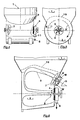
- Fig. 1 shows the lower part of a container for stacking and diluting Paper pulp.
- the container is essentially rotationally symmetrical with vertical center line and contains a first volume 1 (only partially drawn) and a second volume 2.
- the first volume 1 serves to hold the highly consistent paper pulp, which - as already mentioned - stacked in it or treated with chemicals.
- Between the two parts of the container is a frustoconical transition, whereby the flow cross-sectional area in downstream direction is reduced. This results in a large stack volume and prevents the highly consistent paper pulp from becoming uncontrollable sliding down.
- the boundary 10 between the highly consistent fiber and the im second volume 2 of diluted fibrous material is indicated by dashed lines.
- Dilution water W is applied through the side Dilution water pipes 9 and 9 'supplied.
- the existing in the second volume 2 Suspension is in the example shown here by a propeller 7 and a researcherr 4 in a circulation flow 3, which here by two arrows is only hinted at.
- the reamer 4 belongs to a screening device 8, which a Sieve 5 has.
- the sieve 5 contains openings 6, which are part of the second volume 2 moving paper pulp can pass as suspension S, which then over the Acceptance nozzle 11 is discharged.
- the reamer 4 is here e.g. as a wing rotor trained in the immediate vicinity of the sieve 5, i.e.
- the stirring propeller 7 is concentric with here the reamer 4 on the opposite side of the one defining the second volume 2 Container part arranged. It supports the promotional effect of the clearer 4 in that he exerts a hydraulic pressure effect in his center.
- the Stirring propeller 7 in the same direction as the reamer 4, but also in be driven in the opposite direction. This allows the intensity of the Influence rotational movement. If the scraper 4 is also arriving To crush fiber agglomerations, it may be advantageous to use the stirring propeller 7 to run in the opposite direction so that a greater relative speed between the reamer 4 and the suspension sucked by it is generated.
- the addition of the Dilution water W can e.g. through the addition tube 9 into the thickened fibrous material take place or through the addition pipe 9 'into the area of the circulation flow 3, immediately before it reaches border 10.
- Fig. 2 shows the lower part of the container in an external view opposite the 1 is offset by 90 °. It essentially shows the outer part of the Screening device 8 and the accept nozzle 11 for the rejected suspension S. Here a removable cover 12 is also drawn, which covers a man hole, which facilitates maintenance and possible repairs in this area.
- FIGS. 2 and 2 is substantially cylindrical in shape with a truncated cone inserted between them, can - as Fig. 3 shows - the second Volume 2 are formed by a lying cylinder in which the Circulation flow 3 can form particularly cheap. It is conceivable that under favorable conditions for the circulation flow 3 the additional Stirring propeller 7 can be omitted.
- the shape shown in Fig. 3 can also with a Stirring propeller combined, e.g. faces the screening device 8.
- the circulation flow 3 also contains a rotational movement, which has essentially the same center line as the agitators. 4 and FIG. 5, an embodiment shown in two different views, becomes a horizontal one Cylinder used for the volume 2, in which, in contrast to Fig. 3 Screening device 8 and the stirring propeller 7 on the end faces of the second volume 2 forming container part are mounted concentrically, so that the center line with the the agitator collapses. This favors the rotational movement 3 '.
- FIG. 6 shows an example of one of the possible embodiments in which Stirring propeller 7 and sieve 8 are not concentrically opposite. Instead, the stirring propeller 7 is above the screening device 8 at an angle ⁇ of 30 ° from the horizontal. It is located directly below the limit 10 and is particularly well suited to the circulation flow 3 directly on the To establish the border area between high consistency substance and suspension. The replacement and Dilution of the highly consistent substance is particularly effective and the Circulation flow 3 leads directly into the central area of the scraper 4. The Dilution water W is through the addition pipe 9 'in the on the border 10th directed part of the circulation flow 3 is pumped.
Abstract
Description
Die Erfindung bezieht sich auf ein Verfahren gemäß dem Oberbegriff des Anspruchs 1
sowie auf einen Behälter gemäß dem Oberbegriff des Anspruchs 16.The invention relates to a method according to the preamble of
Verfahren dieser Art werden angewendet, um bereits aufgelösten Papierfaserstoff mit einem Trockengehalt, der z. B. zwischen 20 und 40 % liegt, so zu stapeln, daß er über eine gewünschte Verweilzeit In diesem Zustand verbleibt, um z. B. den Faserstoff zu bevorraten oder eine chemische Reaktion ablaufen zu lassen. In der Regel wird dabei ein Behälter zur Aufnahme des Papierfaserstoffes verwendet. Bekanntlich ist bei vielen chemischen Reaktionen eine Mindestverweilzeit erforderlich, wobei es auch Fälle gibt, bei denen die Verweilzeit weder unter- noch überschritten werden darf, also innerhalb einer bestimmten Bandbreite liegen sollte. Ein typischer Anwendungsfall ist die Bleiche von hochkonsistentem Papierfaserstoff. Grundsätzlich wird dabei eine höhere Konsistenz angestrebt, um erstens das benötigte Volumen so gering wie möglich zu halten und zweitens die Effektivität der chemischen Reaktion zu begünstigen. In der Regel wird auch eine Temperatur deutlich über der der Umgebung eingestelltMethods of this type are used to make up already dissolved paper pulp a dryness, e.g. B. is between 20 and 40% to stack so that it over a desired dwell time remains in this state, e.g. B. the pulp too stockpile or run a chemical reaction. As a rule, a Containers used to hold the paper pulp. It is known to many chemical reactions require a minimum dwell time, although there are cases where the dwell time must not be undercut or exceeded, i.e. within a certain bandwidth should be. A typical application is bleaching of highly consistent paper pulp. Basically there is a higher consistency aimed at firstly to keep the required volume as low as possible and second, to favor the effectiveness of the chemical reaction. As a rule, too a temperature set well above that of the environment
In den meisten Fällen ist der Papierfaserstoff in der Stapelkonsistenz nicht pumpfähig, was seine Handhabung erschwert. Aus diesem Grunde wird der Papierfaserstoff nach Ablauf der chemischen Reaktion mindestens so weit verdünnt, daß er pumpfähig ist. Dieses Verdünnen erfolgt oft außerhalb des Behälters, da die Verdünnung innerhalb des Behälters zu Problemen der Betriebssicherheit führen kann.In most cases, the paper pulp is not pumpable in the stack consistency, which makes it difficult to use. For this reason, the paper pulp is after The course of the chemical reaction is diluted at least to such an extent that it is pumpable. This dilution is often done outside the container because the dilution is inside the container Container can lead to operational safety problems.
Die DE-OS 35 22 395 C1 zeigt einen Lagerbehälter (Turm) für Altpapier. Dieser dient der chemischen Behandlung von verschmutztem unaufgelösten Altpapier. Das Verfahren zielt also darauf, den als Altpapier angefallenen Rohstoff zunächst chemisch und in hochkonsistentem Zustand so vorzubehandeln, daß er anschließend mit einem im Behälterboden angeordneten Auflöserotor bearbeitet werden kann. Dabei sind der beschriebene Lagerbehälter und der Auflöserotor auf den nicht aufgelösten, also noch aufzulösenden Rohstoff abgestimmt und entsprechend ausgestaltet.DE-OS 35 22 395 C1 shows a storage container (tower) for waste paper. This serves the chemical treatment of dirty undissolved waste paper. The procedure aims to chemically and in the raw paper to pretreat the highly consistent condition so that it can then be Container bottom arranged opening rotor can be edited. Here are the described storage container and the opening rotor on the unresolved, so still raw material to be resolved and designed accordingly.
In der EP 0 475 669 B1 sowie der EP-A-0 686 578 wird ein Stapelbehälter gezeigt, in dessen Bodenbereich eine Verdünnung durch Zufuhr von wasser und Vermischung mit Hilfe eines Propellers erfolgt. Dieses Vorgehen führt zwar dazu, daß sich eine pumpfähige Suspension herstellen läßt, diese ist aber sehr ungleichmäßig, so daß z.B. vorgeschlagen wird, Pumpen an verschiedenen Stellen anzusetzen, die verschiedene Stoffdichten der Suspension vertragen.EP 0 475 669 B1 and EP-A-0 686 578 show a stacking container in the bottom area of which one Dilution by adding water and mixing using a propeller he follows. This procedure leads to a pumpable suspension can be produced, but this is very uneven, so that e.g. it is proposed Pumps to be placed in different places, the different material densities of the Tolerate suspension.
Es ist Aufgabe der vorliegenden Erfindung, ein Verfahren sowie einen Behälter zu schaffen, mit dem sich eine zuverlässige Möglichkeit zum Stapeln des hochkonsistenten Papierfaserstoffes bietet, wobei gleichzeitig das Verdünnen und Abpumpen mit einfachen Mitteln möglich gemacht werden soll.It is an object of the present invention to provide a method and a container with which a offers a reliable possibility of stacking the highly consistent paper pulp, at the same time making dilution and pumping possible with simple means shall be.
Diese Aufgabe wird durch im Kennzeichen der Ansprüche 1 und 16 genannten Merkmale erfüllt.
weitere Ausgestaltungen sind den abhängigen Ansprüchen zu entnehmen.This object is achieved by the features mentioned in the characterizing part of
Mit Hilfe des erfindungsgemäßen Verfahrens wird eine kontrollierte Verdünnungsströmung unterhalb des hochkonsistenten Papierfaserstoffes erzeugt, wobei eine Suspension gebildet und durch die Siebvorrichtung (insbesondere kontinuierlich) abgepumpt wird. Da die Siebvorrichtung mit einem Räumer versehen ist, wird vermieden, daß sie verstopft. In den Fällen, in denen das Herauslösen von hochkonsistenten Stoffansammlungen aus dem über der Suspension liegenden Bereich nicht vermieden werden kann, erfolgt deren Zirkulation unter Mitwirkung des Räumers so lange, bis sie sich mit Wasser verdünnt und wieder aufgelöst haben. Eine solche Wiederauflösung erfordert zwar nur geringe Kräfte, sie ist aber erforderlich, da sonst bei den Stoffpumpen Schwierigkeiten auftreten können. Zur Aufbringung der bei der Wiederauflösung benötigten Kräfte ist der Räumer, der sich zur Siebfreihaltung in dichter Nähe zum Sieb bewegt, sehr gut geeignet.With the help of the method according to the invention, a controlled Dilution flow generated below the highly consistent pulp, where a suspension is formed and by the screening device (in particular continuously) is pumped out. Since the screening device is provided with a scraper avoided clogging it. In cases where the removal of highly consistent collections of substances from the area above the suspension cannot be avoided, their circulation takes place with the participation of the scraper until they have diluted with water and dissolved again. Such Redissolution does not require much force, but it is necessary because otherwise Difficulties may arise with the fabric pumps. To apply the at the The force needed to redissolve is the scraper, which is used to keep the screen free Moving close to the sieve, very suitable.
Die Erfindung und ihre Vorteile werden erläutert anhand von Zeichnungen. Dabei zeigen:
- Fig. 1
- einen Behälter zur Ausführung des erfindungsgemäßen Verfahrens, geschnitten in Seitenansicht;
- Fig. 2
- eine andere Seitenansicht von außen des Gegenstandes der Fig. 1;
- Fig. 3
- eine Variante eines Behälters zur Ausführung des erfindungsgemäßen Verfahrens, Teilansicht,
- Fig. 4
- eine weitere Variante;
- Fig. 5
- den in Fig. 4 gezeigten Gegenstand um 90° gedreht und geschnitten;
- Fig. 6
- eine weitere Variante.
- Fig. 1
- a container for performing the method according to the invention, cut in side view;
- Fig. 2
- another side view from the outside of the object of Fig. 1;
- Fig. 3
- a variant of a container for performing the method according to the invention, partial view,
- Fig. 4
- another variant;
- Fig. 5
- the object shown in Figure 4 rotated by 90 ° and cut.
- Fig. 6
- another variant.
Alle Figuren deuten die zur Durchführung des Verfahrens verwendeten Vorrichtungen lediglich an, ohne konstruktive Details zu offenbaren.All figures indicate the devices used to carry out the method just on, without revealing constructive details.
Fig. 1 zeigt den unteren Teil eines Behälters zum Stapeln und Verdünnen von
Papierfaserstoff. Der Behälter ist hier im wesentlichen rotationssymmetrisch mit
senkrechter Mittellinie und enthält ein erstes Volumen 1 (nur teilweise gezeichnet)
und ein zweites Volumen 2. Das erste Volumen 1 dient der Aufnahme des
hochkonsistenten Papierfaserstoffs, welcher darin - wie bereits erwähnt - gestapelt
oder mit Chemikalien behandelt wird. Zwischen den beiden Teilen des Behälters ist ein
kegelstumpfförmiger Übergang, wodurch die Strömungsquerschnittsfläche in
stromabwärtiger Richtung verkleinert wird. Das ergibt ein großes Stapelvolumen und
hindert den hochkonsistenten Papierfaserstoff daran, unkontrollierbar
herabzurutschen. Die Grenze 10 zwischen dem hochkonsistenten Faserstoff und dem im
zweiten Volumen 2 verdünnten Faserstoff ist gestrichelt angedeutet. Dabei handelt es
sich nicht um eine scharf definierte Fläche, da sie sich - je nach
Betriebszustand - ständig verändert. Verdünnungswasser W wird durch seitlich angebrachte
Verdünnungswasserrohre 9 bzw. 9' zugeführt. Die im zweiten Volumen 2 vorhandene
Suspension wird in dem hier gezeigten Beispiel durch einen Rührpropeller 7 und einen
Räumer 4 in eine Zirkulationsströmung 3 versetzt, welche hier durch zwei Pfeile
lediglich angedeutet ist. Der Räumer 4 gehört zu einer Siebvorrichtung 8, welche ein
Sieb 5 aufweist. Das Sieb 5 enthält Öffnungen 6, die ein Teil des im zweiten Volumen 2
bewegten Papierfaserstoffes als Suspension S passieren kann, die dann über den
Gutstoffstutzen 11 abgeführt wird. Der Räumer 4 ist hier z.B. als Flügelrotor
ausgebildet, der in unmittelbarer Nähe des Siebes 5, d.h. in einem Abstand zwischen 1
und 10 mm, entlang bewegt wird. Neben der Freihaltung des Siebes 5 dient der
Flügelrotor auch dazu, eine Umwälzströmung zu erzeugen, welche ähnlich wie bei einem
Pumplaufrad die Flüssigkeit zentral ansaugt und radial beschleunigt. Diesei Bewegung
überlagert sich außerdem eine reine Rotationsbewegung, die hier In der Seitenansicht
nicht dargestellt werden kann, auf die aber später noch eingegangen wird. Die Intensität
der Rotationsbewegung hängt sehr stark von der Form des Behälters, des Räumers und
von eventuellen Strömungseinbauten ab. Der Rührpropeller 7 ist hier konzentrisch mit
dem Räumer 4 auf der gegenüberliegenden Seite des das zweite Volumen 2 definierenden
Behälterteils angeordnet. Er unterstützt die Förderwirkung des Räumers 4 insofern, als
er in seinem Zentrum eine hydraulische Druckwirkung ausübt. Grundsätzlich kann der
Rührpropeller 7 im gleichen Drehsinn wie der Räumer 4, aber auch im
entgegengesetzten Drehsinn angetrieben werden. Dadurch läßt sich die Intensität der
Rotationssbewegung beeinflussen. Wenn der Räumer 4 auch ankommende
Faseragglomerationen zerkleinern soll, kann es von Vorteil sein, den Rührpropeller 7
entgegengesetzt laufen zu lassen, damit eine größere Relativgeschwindigkeit zwischen
dem Räumer 4 und der von ihm angesaugten Suspension erzeugt wird. Die Zugabe des
Verdünnungswassers W kann z.B. durch das Zugaberohr 9 in den eingedickten Faserstoff
erfolgen oder durch das Zugaberohr 9' in den Bereich der Zirkulationsströmung 3,
unmittelbar bevor sie an die Grenze 10 gelangt.Fig. 1 shows the lower part of a container for stacking and diluting
Paper pulp. The container is essentially rotationally symmetrical with
vertical center line and contains a first volume 1 (only partially drawn)
and a
Fig. 2 zeigt den unteren Teil des Behälters in einer Ansicht von außen, die gegenüber der
in der Fig. 1 um 90° versetzt ist. Sie zeigt im wesentlichen den außenliegenden Teil der
Siebvorrichtung 8 sowie den Gutstoffstutzen 11 für die ausgeleitete Suspension S. Hier
ist auch ein herausnehmbarer Deckel 12 gezeichnet, der ein Mann-Loch abdeckt,
welches die Wartung und eventuelle Reparaturen in diesem Bereich erleichtert.Fig. 2 shows the lower part of the container in an external view opposite the
1 is offset by 90 °. It essentially shows the outer part of the
Während der in Fig. und 2 gezeigte Behälter im wesentlichen eine zylindrische Form
mit dazwischen eingesetztem Kegelstumpf aufweist, kann - wie Fig. 3 zeigt - das zweite
Volumen 2 durch einen liegenden Zylinder gebildet werden, in dem sich die
Zirkulationsströmung 3 besonders-günstig ausbilden kann. Es ist denkbar, daß unter
günstigen Voraussetzungen für die Zirkulationsströmung 3 der zusätzliche
Rührpropeller 7 entfallen kann. Die in Fig. 3 gezeigte Form kann aber auch mit einem
Rührpropeller kombiniert sein, der z.B. der Siebvorrichtung 8 gegenübersteht.While the container shown in FIGS. 2 and 2 is substantially cylindrical in shape
with a truncated cone inserted between them, can - as Fig. 3 shows - the
Wie schon erwähnt, enthält die Zirkulationsströmung 3 auch eine Rotationsbewegung,
die im wesentlichen dieselbe Mittellinie hat wie die Rührorgane. Bei der in den Fig. 4
und 5 in zwei verschiedenen Ansichten gezeigten Ausführungsform wird ein liegender
Zylinder für das Volumen 2 verwendet, bei dem im Gegensatz zur Fig. 3 die
Siebvorrichtung 8 und der Rührpropeller 7 an den Stirnseiten des das zweite Volumen 2
bildenden Behälterteils konzentrisch angebracht sind, so daß dessen Mittellinie mit der
der Rührorgane zusammenfällt. Das begünstigt die Rotationsbewegung 3'.As already mentioned, the
In Fig. 6 ist exemplarisch eine der möglichen Ausführungsformen gezeigt, bei der
Rührpropeller 7 und Siebvorrichtung 8 sich nicht konzentrisch gegenüberliegen.
Stattdessen ist der Rührpropeller 7 oberhalb der Siebvorrichtung 8 mit einem Winkel
α von 30° gegenüber der Horizontalen angeordnet. Er befindet sich unmittelbar unter
der Grenze 10 und ist besonders gut geeignet, die Zirkulationsströmung 3 direkt auf den
Grenzbereich zwischen Hochkonsistenzstoff und Suspension zu richten. Die Ablösung und
Verdünnung des hochkonsistenten Stoffes wird dadurch besonders wirksam und die
Zirkulationsströmung 3 führt direkt in den zentralen Bereich des Räumers 4. Das
Verdünnungswasser W wird durch das Zugaberohr 9' in den auf die Grenze 10
gerichteten Teil der Zirkulationsströmung 3 eingepumpt.6 shows an example of one of the possible embodiments in which
Claims (21)
- Method for stacking and diluting paper pulp, which is stacked, in a high consistency condition, in a first volume (1) for a defined delay time, and is then taken to a second volume (2), which adjoins the first one in a downstream direction and in which it is diluted until it is capable of being pulped, a circulation flow (3) being produced in the second volume (2) that picks up and dilutes the high consistency pulp located at the edge of the first volume (1),
characterised in that
the circulation flow moves the pulp to a strainer (5) which is kept clear by a moving scraper (4); and that the diluted pulp is drawn off through the strainer (5) in the form of a suspension (S). - Method as in Claim 1,
characterised in that
the high consistency pulp has a crumbly structure. - Method as in Claim 1 or 2,
characterised in that
the high consistency pulp is waste paper which has been pulped, cleaned and then re-concentrated. - Method as in Claim 1, 2 or 3,
characterised in that
the high consistency pulp in the first volume (1) has a solids content of 20 to 40 %. - Method as in one of the preceding Claims,
characterised in that
the pulp is chemically bleached in the first volume (1). - Method as in one of the preceding Claims,
characterised in that
the pulp is drawn off from the second volume (2) with a maximum solids content of 8 %. - Method as in one of the preceding Claims,
characterised in that
the scraper (4) pulps or breaks up agglomerations of fibres. - Method as in one of the preceding Claims,
characterised in that
the circulation flow (3) is produced by the scraper (4). - Method as in one of the preceding Claims,
characterised in that
the circulation flow (3) is assisted by an agitator (7) whose hydraulic displacement effect goes in the same direction as that of the scraper (4). - Method as in Claim 9,
characterised in that the agitator (7) is operated to produce a pressure effect, and the scraper (4) to give a suction effect, in each case in the central area. - Method as in one of the preceding Claims,
characterised in that
a specific energy consumption of between 3 kWh/t and 15 kWh/t is imparted by the scraper (4). - Method as in Claim 9, 10 or 11,
characterised in that
the agitator (7) and the scraper (4) are driven to rotate in opposite directions. - Method as in Claim 9, 10, 11 or 12,
characterised in that
the agitator (7) and the scraper (4) are positioned concentrically opposite each other. - Method as in one of the preceding Claims,
characterised in that
the pulp is taken from the first volume (1) to the second volume (2) through a cross-sectional area of flow that gradually becomes narrower, the downstream cross-sectional area of flow being a maximum of 80 % of the upstream area. - Method as in one of the preceding Claims,
characterised in that
the second volume (2) lies beneath the first volume (1). - Container for implementing the method as in one of the preceding Claims, which contains, in its upper area, a first volume (1) to accept the paper pulp in a high consistency condition, and in its lower area has a second volume (2) in which there are means of dilution and of removing the diluted pulp,
characterised in that
there are, in the second volume (2), means of producing hydraulic circulation, comprising an agitator (7) and a strainer facility (8), the strainer facility containing at least one strainer (5) and at least one scraper (4); and the diluted pulp can be drawn off through the strainer (5). - Container as in Claim 16,
characterised in that
the agitator (7) and strainer facility (8) are positioned on the side wall of the lower part of the container and are opposite to each other. - Container as in Claim 16,
characterised in that
the agitator (7) and the strainer facility (8) are positioned on the side wall of the lower part of the container, and are positioned one on top of the other. - Container as in Claim 16, 17 or 18,
characterised in that
the delivery direction of the agitator (7) is horizontal. - Container as in Claim 16, 17 or 18,
characterised in that
the delivery direction of the agitator (7) is slanted upwards at an angle (a) of between 0 and 30°. - Container as in one of Claims 16 to 20,
characterised in that
the strainer (5) is a flat plate containing openings (6).
Applications Claiming Priority (2)
| Application Number | Priority Date | Filing Date | Title |
|---|---|---|---|
| DE19826879 | 1998-06-17 | ||
| DE19826879A DE19826879B4 (en) | 1998-06-17 | 1998-06-17 | Method and container for stacking high consistency paper pulp |
Publications (2)
| Publication Number | Publication Date |
|---|---|
| EP0965682A1 EP0965682A1 (en) | 1999-12-22 |
| EP0965682B1 true EP0965682B1 (en) | 2003-05-07 |
Family
ID=7871097
Family Applications (1)
| Application Number | Title | Priority Date | Filing Date |
|---|---|---|---|
| EP99111616A Expired - Lifetime EP0965682B1 (en) | 1998-06-17 | 1999-06-16 | Method and container for stacking and diluting high consistency pulp |
Country Status (3)
| Country | Link |
|---|---|
| EP (1) | EP0965682B1 (en) |
| AT (1) | ATE239822T1 (en) |
| DE (2) | DE19826879B4 (en) |
Families Citing this family (4)
| Publication number | Priority date | Publication date | Assignee | Title |
|---|---|---|---|---|
| DE10156201C1 (en) | 2001-11-15 | 2002-10-17 | Voith Paper Patent Gmbh | To process high consistency paper fiber materials, an initial high consistency volume is held in a stack for a dwell time, to be taken off at the bottom by a circulation flow for dilution and delivery as a suspension |
| DE102006008763B3 (en) * | 2006-02-24 | 2007-12-06 | Voith Patent Gmbh | Reaction tower for bleaching of fiber materials, comprises cylindrical reaction container, dilution container, and a cylindrical homogenizing container, which has an inlet and outlet for the product to be bleached |
| JP5911873B2 (en) * | 2010-10-13 | 2016-04-27 | アンドリツ オサケユキチュア | Method and configuration for treating pulp |
| CN111576066B (en) * | 2020-06-11 | 2022-03-25 | 郑州磊展科技造纸机械有限公司 | A widen thick liquid pond structure for broke pulper |
Family Cites Families (5)
| Publication number | Priority date | Publication date | Assignee | Title |
|---|---|---|---|---|
| FR2543183B1 (en) * | 1983-03-25 | 1985-07-26 | Lamort E & M | METHOD AND DEVICE FOR SORTING A MIXTURE OF PAPER PULP AND IMPURITIES |
| DE3522395C1 (en) * | 1985-06-22 | 1986-11-20 | J.M. Voith Gmbh, 7920 Heidenheim | Process and arrangement for processing waste paper |
| FI79361B (en) * | 1988-01-05 | 1989-08-31 | Ahlstroem Oy | FOERFARANDE OCH APPARATUR FOER UNDERLAETTANDE AV UTTOEMNING AV FALLROER ELLER LIKNANDE OCH BEHANDLING AV MASSA I SAGDA UTRYMME. |
| FI85392C (en) * | 1990-09-05 | 1992-04-10 | Ahlstroem Oy | ANORDINATION FROM THE URL TO THE MASSAGE. |
| FI98836C (en) * | 1994-06-09 | 1997-08-25 | Ahlstroem Pumput Oy | Consistency pulp tower |
-
1998
- 1998-06-17 DE DE19826879A patent/DE19826879B4/en not_active Expired - Fee Related
-
1999
- 1999-06-16 EP EP99111616A patent/EP0965682B1/en not_active Expired - Lifetime
- 1999-06-16 AT AT99111616T patent/ATE239822T1/en not_active IP Right Cessation
- 1999-06-16 DE DE59905408T patent/DE59905408D1/en not_active Expired - Fee Related
Also Published As
| Publication number | Publication date |
|---|---|
| DE19826879A1 (en) | 1999-12-30 |
| ATE239822T1 (en) | 2003-05-15 |
| EP0965682A1 (en) | 1999-12-22 |
| DE59905408D1 (en) | 2003-06-12 |
| DE19826879B4 (en) | 2005-06-02 |
Similar Documents
| Publication | Publication Date | Title |
|---|---|---|
| DE10156201C1 (en) | To process high consistency paper fiber materials, an initial high consistency volume is held in a stack for a dwell time, to be taken off at the bottom by a circulation flow for dilution and delivery as a suspension | |
| DE2917814C2 (en) | Pulpers for the production of paper stock suspensions | |
| DE2518112C2 (en) | Device for treating paper fibers | |
| EP1679403B1 (en) | Pulper for comminuting and suspending papermaking material | |
| DE2547896A1 (en) | METHOD FOR RECOVERY OF FIBERS IN FIBER MATERIAL, E.G. WASTE PAPER AND DEVICE FOR CARRYING OUT THE PROCEDURE | |
| DE3149135C2 (en) | Device for dissolving waste paper in the thick material area | |
| EP0965682B1 (en) | Method and container for stacking and diluting high consistency pulp | |
| DE1692833A1 (en) | Device for the transfer of wood chips in a continuous digestion process | |
| EP1170417A1 (en) | Method for pulping and cleaning of waste paper containing impurities | |
| EP2238291B1 (en) | Pulper for pulverizing and suspending paper material | |
| DE3605259C1 (en) | Process and installation for removing color particles from a fiber suspension obtained from waste paper | |
| DE4024561C2 (en) | Process and device for processing waste paper | |
| DE3127114A1 (en) | Apparatus for breaking open old paper and for sorting out fibres to be obtained from this for the production of paper, cardboard or paper board | |
| DE102006031904B3 (en) | Paper pulping assembly for paper recovery and recycling has rotor surrounded by ring | |
| DE102021211856B4 (en) | Solvent for producing a suspension of solid particles and a flowable medium | |
| DE60027782T2 (en) | DEVICE FOR SEPARATING A FIBER BREAST SUSPENSION | |
| DE19701129A1 (en) | Breaking-up paper pulp, useful for paper or cardboard manufacture | |
| DE102006008763B3 (en) | Reaction tower for bleaching of fiber materials, comprises cylindrical reaction container, dilution container, and a cylindrical homogenizing container, which has an inlet and outlet for the product to be bleached | |
| EP0971069B1 (en) | Mixing and recirculation circuit | |
| DE2512638A1 (en) | METHOD OF DRAINING A FIBER SUSPENSION AND DEVICE FOR CARRYING OUT THE METHOD | |
| DE975571C (en) | Process for the one-step chlorination of the lignin of cellulose in two phases | |
| DE10255314B4 (en) | Process for the preparation of an aqueous suspension of fibrous material | |
| WO2023280682A1 (en) | Rotor for use in stock preparation | |
| EP1116818A2 (en) | Device for mixing pulp suspension | |
| DE19706404A1 (en) | Removal of fibre clumps from a suspension |
Legal Events
| Date | Code | Title | Description |
|---|---|---|---|
| PUAI | Public reference made under article 153(3) epc to a published international application that has entered the european phase |
Free format text: ORIGINAL CODE: 0009012 |
|
| AK | Designated contracting states |
Kind code of ref document: A1 Designated state(s): AT DE FR GB |
|
| AX | Request for extension of the european patent |
Free format text: AL;LT;LV;MK;RO;SI |
|
| 17P | Request for examination filed |
Effective date: 20000623 |
|
| AKX | Designation fees paid |
Free format text: AT DE FR GB |
|
| RAP1 | Party data changed (applicant data changed or rights of an application transferred) |
Owner name: VOITH PAPER PATENT GMBH |
|
| GRAH | Despatch of communication of intention to grant a patent |
Free format text: ORIGINAL CODE: EPIDOS IGRA |
|
| GRAH | Despatch of communication of intention to grant a patent |
Free format text: ORIGINAL CODE: EPIDOS IGRA |
|
| RTI1 | Title (correction) |
Free format text: METHOD AND CONTAINER FOR STACKING AND DILUTING HIGH CONSISTENCY PULP |
|
| RTI1 | Title (correction) |
Free format text: METHOD AND CONTAINER FOR STACKING AND DILUTING HIGH CONSISTENCY PULP |
|
| GRAA | (expected) grant |
Free format text: ORIGINAL CODE: 0009210 |
|
| AK | Designated contracting states |
Designated state(s): AT DE FR GB |
|
| REG | Reference to a national code |
Ref country code: GB Ref legal event code: FG4D Free format text: NOT ENGLISH |
|
| GBT | Gb: translation of ep patent filed (gb section 77(6)(a)/1977) |
Effective date: 20030507 |
|
| REF | Corresponds to: |
Ref document number: 59905408 Country of ref document: DE Date of ref document: 20030612 Kind code of ref document: P |
|
| ET | Fr: translation filed | ||
| PLBE | No opposition filed within time limit |
Free format text: ORIGINAL CODE: 0009261 |
|
| STAA | Information on the status of an ep patent application or granted ep patent |
Free format text: STATUS: NO OPPOSITION FILED WITHIN TIME LIMIT |
|
| 26N | No opposition filed |
Effective date: 20040210 |
|
| PGFP | Annual fee paid to national office [announced via postgrant information from national office to epo] |
Ref country code: GB Payment date: 20060615 Year of fee payment: 8 |
|
| PGFP | Annual fee paid to national office [announced via postgrant information from national office to epo] |
Ref country code: DE Payment date: 20060616 Year of fee payment: 8 Ref country code: AT Payment date: 20060616 Year of fee payment: 8 |
|
| PGFP | Annual fee paid to national office [announced via postgrant information from national office to epo] |
Ref country code: FR Payment date: 20060619 Year of fee payment: 8 |
|
| GBPC | Gb: european patent ceased through non-payment of renewal fee |
Effective date: 20070616 |
|
| PG25 | Lapsed in a contracting state [announced via postgrant information from national office to epo] |
Ref country code: AT Free format text: LAPSE BECAUSE OF NON-PAYMENT OF DUE FEES Effective date: 20070616 |
|
| REG | Reference to a national code |
Ref country code: FR Ref legal event code: ST Effective date: 20080229 |
|
| PG25 | Lapsed in a contracting state [announced via postgrant information from national office to epo] |
Ref country code: DE Free format text: LAPSE BECAUSE OF NON-PAYMENT OF DUE FEES Effective date: 20080101 |
|
| PG25 | Lapsed in a contracting state [announced via postgrant information from national office to epo] |
Ref country code: GB Free format text: LAPSE BECAUSE OF NON-PAYMENT OF DUE FEES Effective date: 20070616 |
|
| PG25 | Lapsed in a contracting state [announced via postgrant information from national office to epo] |
Ref country code: FR Free format text: LAPSE BECAUSE OF NON-PAYMENT OF DUE FEES Effective date: 20070702 |