EP0965452A1 - Ink supply device and ink-jet recording head - Google Patents
Ink supply device and ink-jet recording head Download PDFInfo
- Publication number
- EP0965452A1 EP0965452A1 EP99111675A EP99111675A EP0965452A1 EP 0965452 A1 EP0965452 A1 EP 0965452A1 EP 99111675 A EP99111675 A EP 99111675A EP 99111675 A EP99111675 A EP 99111675A EP 0965452 A1 EP0965452 A1 EP 0965452A1
- Authority
- EP
- European Patent Office
- Prior art keywords
- ink
- filter
- flow passage
- filter box
- recording head
- Prior art date
- Legal status (The legal status is an assumption and is not a legal conclusion. Google has not performed a legal analysis and makes no representation as to the accuracy of the status listed.)
- Granted
Links
Images

Classifications
-
- B—PERFORMING OPERATIONS; TRANSPORTING
- B41—PRINTING; LINING MACHINES; TYPEWRITERS; STAMPS
- B41J—TYPEWRITERS; SELECTIVE PRINTING MECHANISMS, i.e. MECHANISMS PRINTING OTHERWISE THAN FROM A FORME; CORRECTION OF TYPOGRAPHICAL ERRORS
- B41J2/00—Typewriters or selective printing mechanisms characterised by the printing or marking process for which they are designed
- B41J2/005—Typewriters or selective printing mechanisms characterised by the printing or marking process for which they are designed characterised by bringing liquid or particles selectively into contact with a printing material
- B41J2/01—Ink jet
- B41J2/17—Ink jet characterised by ink handling
- B41J2/175—Ink supply systems ; Circuit parts therefor
- B41J2/17563—Ink filters
-
- B—PERFORMING OPERATIONS; TRANSPORTING
- B41—PRINTING; LINING MACHINES; TYPEWRITERS; STAMPS
- B41J—TYPEWRITERS; SELECTIVE PRINTING MECHANISMS, i.e. MECHANISMS PRINTING OTHERWISE THAN FROM A FORME; CORRECTION OF TYPOGRAPHICAL ERRORS
- B41J2/00—Typewriters or selective printing mechanisms characterised by the printing or marking process for which they are designed
- B41J2/005—Typewriters or selective printing mechanisms characterised by the printing or marking process for which they are designed characterised by bringing liquid or particles selectively into contact with a printing material
- B41J2/01—Ink jet
- B41J2/17—Ink jet characterised by ink handling
- B41J2/19—Ink jet characterised by ink handling for removing air bubbles
-
- B—PERFORMING OPERATIONS; TRANSPORTING
- B41—PRINTING; LINING MACHINES; TYPEWRITERS; STAMPS
- B41J—TYPEWRITERS; SELECTIVE PRINTING MECHANISMS, i.e. MECHANISMS PRINTING OTHERWISE THAN FROM A FORME; CORRECTION OF TYPOGRAPHICAL ERRORS
- B41J2202/00—Embodiments of or processes related to ink-jet or thermal heads
- B41J2202/01—Embodiments of or processes related to ink-jet heads
- B41J2202/12—Embodiments of or processes related to ink-jet heads with ink circulating through the whole print head
Definitions
- the present invention relates to an ink supply device and a recording head of an ink-jet recording apparatus for discharging flying liquid drops of ink as a recording liquid as ink droplets from a discharge port to perform recording on recording paper, more concretely to an ink supply device which is provided with a removing device for removing dust, and to a recording head.
- an ink-jet recording head it is constructed so as to supply ink to a common chamber communicating with a discharge port, in which a filter device having a filter for preventing contamination with fine dust or the like which may be a cause of nozzle clogging is provided in a passage for introducing the ink supplied from an ink tank.
- a filter device having a filter for preventing contamination with fine dust or the like which may be a cause of nozzle clogging is provided in a passage for introducing the ink supplied from an ink tank.
- Such filter device is generally of a type in which a filter box is connected to a pipe for introducing the ink.
- a filter is disposed in the filter box, and the diameter of the filter is normally larger than the diameter of the pipe. For this reason, an inside diameter of the pipe in the vicinity of the filter is increased towards the filter diameter, resulting in a bell-bottomed shape of the pipe of this portion.
- an ink supply device having an ink flow passage for communicating an ink containing part for containing an ink with a discharge part for discharging the ink
- the ink flow passage is characterized by a filter device including a filter and a filter box for containing the filter and provided with an ink inlet port and an ink outlet port, wherein an area at the ink inlet port side of the filter box is disposed beneath an area at the ink outlet port side of the filter box, and an inside diameter of the ink flow passage at the ink inlet port side of the filter box is narrowed in a diameter to be smaller than the inside diameter of the ink flow passage immediately before expanding into a bell-bottomed shape towards the filter.
- the flow rate of the ink passing through the narrowed orifice-formed part is increased, which is offset each other by a mutual effect of a relaxation of an ink flow rate in a box member having a cross-sectional area expanding in a bell-bottomed shape towards the filter having a large diameter, thereby preventing an occurrence of a generation of a bubble due to a stagnation of an ink flow and obtaining a highly reliable ink supply device and an ink-jet recording head without an unstable ink discharge or an insufficient ink refill.
- Fig. 1 is a perspective view showing the shape of an ink-jet recording head 1 according to the present invention
- Fig. 2 is a schematic view of a filter box which is best showing the feature of the ink-jet recording head of the present invention.
- the ink-jet recording head 1 of the present invention is constructed integrally from an electrothermal converter (electrothermal conversion element) which is film-formed on a substrate by means of a semiconductor production process such as etching, deposition, sputtering and the like, an ink flow passage having a common liquid chamber, a grooved ceiling plate 2 which is a discharge port formation member having an electrode and a discharge port (nozzle), a base plate 5 having a printed circuit board 3 and a heater board 4, an ink supply system unit 8 having an ink supply pipe passage 7 provided with a filter device 10 having a filter box 6, and the like.
- a recording ink is supplied from an ink tank to a rear part at both ends of the grooved ceiling plate 2 which is a formation member of the discharge port, an ink flow passage and a common liquid chamber of the ink-jet recording head 1.
- the ink supply pipe passage 7 of the ink supply system unit 8 is adapted to be connected with a piping from the ink tank, and a filter device 10 is provided at the connection part which has a filter box 6 provided with a filter for preventing contamination with fine dust and the like from the ink tank.
- the ink supply pipe passage 7 is branched into branch pipe passages 7a an 7b, tips of the respective branch pipe passages 7a and 7b being connected to both ends of the grooved ceiling plate 2, and the mounting protrusions 7c and 7c provided halfway in the branched pipe passages 7a and 7b are mounted respectively to the mounting holes 5a and 5a of the base plate 5.
- the ink supplied to the ink-jet recording head 1 of the above construction is supplied by a capillary phenomenon into an ink liquid passage formed of the grooved ceiling plate 2, and stably held by forming a meniscus on an ink discharge port surface at the tip of the liquid passage.
- the ink-jet recording method is an ink-jet method of a type for discharging a liquid by a thermal energy, and by arranging the ink discharge ports in a high density, a very fine recording can be achieved.
- the filter device 10 of the present invention comprises two truncated conical box members 16 and 17 joined in the opposite directions, and a filter box 14 having a filter 16 provided in the joined portion between these box members 16 and 17.
- An inlet side pipe 12 is connected to an inlet port of the box member 16, on the other hand, an outlet side pipe 13 is connected to an outlet of the box member 17.
- a tip part 12a of the inlet side pipe 12 is provided with a protruded portion 12b on its entire inner periphery, thus forming the tip.
- the ink inlet side filter box member 16 is disposed beneath the ink outlet side filter box member 17 through the filter 15 so that the ink flow is in a vertical upward direction. That is, in the recording head shown in Fig. 1, the discharge port is used in a vertical downward direction.
- the filter box 14 provided with the filter 15 has a so-called abacus bead form in which two truncated conical box members 16 and 17 are joined with each other in the opposite directions at the bottom surface sides, the filter 15 of a diameter D is integrally formed at the joined portion at the center of the filter box 14, the inlet side pipe 12 of a diameter d1 is connected at the ink inlet side, and the outlet side pipe 13 of the same diameter d1 is connected at the ink outlet side.
- the walls for these inlet side pipe 12 and outlet side pipe 13, the box members 16 and 17 of the filter box 14 and the like are not shown in the figure, and can be formed in the appropriate thicknesses. Further, when the filter box 14 is made of a transparent or translucent synthetic resin or the like, it is advantageous for checking the inside state visually.
- the inlet side pipe 12 and the outlet side pipe 13 are both made of a pipe having the same diameter d1
- the tip part 12a of the inlet side pipe 12 is tapered to a diameter d2 at the inlet port 14a into the filter box 14. That is, the outlet port of the tip part 12a of the inlet side pipe 12 is the inlet port 14a of the filter box 14, forming an orifice of a diameter d2. Therefore, the inlet port 14a of the filter box 14 also has a diameter d2.
- the protruded portion 12b is provided on the outer periphery of the constricted part by adhering an appropriate filling material or molding material to approximately to the same diameter as the inlet side pipe 12 so that the strength of this portion is increased.
- the filter box 14 is tapered from the inlet port 14a towards inside the filter box 14 to form a bell-bottomed shape expanding towards the filter diameter, and after passing the filter 15 on the contrary, similarly tapered to converge in a bell-bottomed shape towards the outlet side pipe 13.
- the inlet side pipe 12 having the diameter d1 is tapered down at the connection part with the filter box 14, diameter of the outlet port of the tapered tip part 12a is the same diameter d2 as that of the inlet port 14a of the filter box 14, and the inlet side pipe 12 and the outlet side pipe 13 are the same in diameter, where since the filter 15 has a diameter of D, there is a relation of D > d1 > d2 among these diameters d1, d2, and D.
- the filter device 10 is disposed which has the filter box 14 provided with the filter 15 for preventing contamination of fine dust in the passage for supplying the ink to the common liquid chamber of the grooved ceiling plate 2, the inside diameter d1 of the inlet side pipe 12 at the inlet side of the box member 16 of the filter box 14 is narrowed by one step, and at the part before immediately expanding to a bell-bottomed shape towards the diameter of the filter 15, is formed in an orifice-shape having a diameter d2 at the hole of the outlet port of the tip part 12a.
- the flow rate of the ink passing through this part is increased, and it can offset a decrease in flow rate due to the expansion in the bell-bottomed shape towards the filter 15 having the diameter D to prevent a generation of a bubble due to a stagnation of the ink.
- a turbulent flow of the ink is generated in the interior of the filter box member 16, even when a bubble adheres to the surface at the ink inlet side of the filter, the bubble is divided into small pieces so that they can pass through the filter and move upward (to the downstream side).
- the bubble can be destructed to flow into the common liquid chamber of the recording head through the filter 15 to be discharged from the discharge port of the ink discharge port surface 2a, that is, from the nozzle, thereby it can construct a highly reliable ink-jet recording head without an occurrence of an unstable discharge or an insufficient ink refill.
- the inside diameter d1 of the ink inlet pipe 12 can be determined so that an ink supply failure is not generated to the head when the ink flow rate is a maximum, and the filter diameter is a minimum in view of a down-sizing of the apparatus itself.
- the maximum value of the ink flow rate can be calculated from the number of the discharge ports of the recording head, the ink discharge amount from the discharge port, the driving frequency and the like, and when the respective values are increased, the maximum value of the ink flow rate is required to be estimated at a large value.
- the tapered shape of the tip part 12a of the inlet pipe since a loss coefficient ⁇ due to a rapid reduction loss is increased if it has a stepped shape, it is desirable that the tapered shape be such that the sectional area continuously decreases with respect to the ink flow direction (vertical upward). Then, the inventors have determined the inner surface shape of the tip part 12a to be approximately a truncated conical shape, where an angle is ⁇ between the part of continuously changing cross-sectional shape and the inside wall of the ink flow passage, investigated an optimum range of the angle ⁇ and obtained the result shown in Table 1 below. Sample d1 (mm) d2 (mm) ⁇ (deg.) Presence of remaining bubble 1 10 5 10 X 2 10 5 20 X 3 10 5 30 ⁇ 4 10 5 40 ⁇ 5 10 5 45 ⁇ 6 10 5 50 X
- the range of the angle 30° ⁇ ⁇ ⁇ 45° can provide the above effect without being affected by the respective diameters when the diameters d1 and d2 meet the above desirable relation.
- Fig. 3 illustrates a second embodiment of the ink-jet recording apparatus according to the present invention, of which the basic construction of an inlet side pipe 22, an outlet side pipe 23, a filter 25 and the like is the same as in the first embodiment.
- a top surface 26b of the inlet side box member 26 of a filter box 24 is broad and flat, and an inlet port 26a is provided at the center to form an orifice.
- the constricted part on the periphery of the part joining the tip part 22a of the inlet side pipe 22 with the top surface 26b of the box member 26 is provided with a protruded part 22b by adhering an appropriate filling material or molding material to make the outer peripheral surface in flat.
- the inside diameter d1 of the inlet side pipe 22 to the ink inlet side box member 26 of the filter box 24 is reduced by one step, immediately before expanding into a bell-bottomed shape towards the outer diameter of the filter 25, that is, forming an orifice shape having a diameter d2 at the hole of the outlet port of the tip part 22a, thus the flow rate of the ink passing this part is increased. Further, the ink flow rate is relaxed in the box member 26 having a cross-sectional area sharply changing by expanding into the bell-bottomed shape towards the filter 25 having a diameter D to offset with each other, thereby preventing generation of a bubble due to a stagnation of the ink.
- Fig. 4 illustrates a third embodiment of the ink-jet recording apparatus of the present invention.
- the above-described filter device is provided in a replaceable ink tank, rather than the recording head.
- numeral 108 denotes an ink tank as an ink containing part, which is provided with an atmosphere communicating hole 101 for communicating with the atmosphere and an ink supply port 102 for conducting the ink to the outside.
- 103 is an ink inlet port for introducing a recirculated ink.
- 109 is a pump for pumping the ink
- 110 is a power supply for driving the pump
- 111 is a switch for controlling the drive.
- the ink blows from the ink tank, passing through the filter device 106 of the present invention and through an ink supply passage 122 to the head 112.
- the ink is recirculated by pumping from the head through an ink supply passage 121 as an ink return passage to the ink tank.
- the present invention achieves distinct effects when applied to a recording head or a recording apparatus which has means for generating thermal energy such as electrothermal transducers or laser light, and which causes changes in ink by the thermal energy so as to eject ink. This is because such a system can achieve a high density and high resolution recording.
- the on-demand type apparatus has electrothermal transducers, each disposed on a sheet or liquid passage that retains liquid (ink), and operates as follows: first, one or more drive signals are applied to the electrothermal transducers to cause thermal energy corresponding to recording information; second, the thermal energy induces sudden temperature rise that exceeds the nucleate boiling so as to cause the film boiling on heating portions of the recording head; and third, bubbles are grown in the liquid (ink) corresponding to the drive signals. By using the growth and collapse of the bubbles, the ink is expelled from at least one of the ink ejection orifices of the head to form one or more ink drops.
- the drive signal in the form of a pulse is preferable because the growth and collapse of the bubbles can be achieved instantaneously and suitably by this form of drive signal.
- a drive signal in the form of a pulse those described in U.S. patent Nos. 4,463,359 and 4,345,262 are preferable.
- the rate of temperature rise of the heating portions described in U.S. patent No. 4,313,124 be adopted to achieve better recording.
- U.S. patent Nos. 4,558,333 and 4,459,600 disclose the following structure of a recording head, which is incorporated to the present invention: this structure includes heating portions disposed on bent portions in addition to a combination of the ejection orifices, liquid passages and the electrothermal transducers disclosed in the above patents. Moreover, the present invention can be applied to structures disclosed in Japanese Patent Application Laying-open Nos. 59-123670 (1984) and 59-138461 (1984) in order to achieve similar effects.
- the former discloses a structure in which a slit common to all the electrothermal transducers is used as ejection orifices of the electrothermal transducers, and the latter discloses a structure in which openings for absorbing pressure waves caused by thermal energy are formed corresponding to the ejection orifices.
- the present invention can be also applied to a so-called full-line type recording head whose length equals the maximum length across a recording medium.
- a recording head may consists of a plurality of recording heads combined together, or one integrally arranged recording head.
- the present invention can be applied to various serial type recording heads: a recording head fixed to the main assembly of a recording apparatus; a conveniently replaceable chip type recording head which, when loaded on the main assembly of a recording apparatus, is electrically connected to the main assembly, and is supplied with ink therefrom; and a cartridge type recording head integrally including an ink reservoir.
- a recovery system or a preliminary auxiliary system for a recording head as a constituent of the recording apparatus because they serve to make the effect of the present invention more reliable.
- the recovery system are a capping means and a cleaning means for the recording head, and a pressure or suction means for the recording head.
- the preliminary auxiliary system are a preliminary heating means utilizing electrothermal transducers or a combination of other heater elements and the electrothermal transducers, and a means for carrying out preliminary ejection of ink independently of the ejection for recording. These systems are effective for reliable recording.
- the number and type of recording heads to be mounted on a recording apparatus can be also changed. For example, only one recording head corresponding to a single color ink, or a plurality of recording heads corresponding to a plurality of inks different in color or concentration can be used.
- the present invention can be effectively applied to an apparatus having at least one of the monochromatic, multi-color and full-color modes.
- the monochromatic mode performs recording by using only one major color such as black.
- the multi-color mode carries out recording by using different color inks, and the full-color mode performs recording by color mixing.
- inks that are liquid when the recording signal is applied can be used: for example, inks can be employed that solidify at a temperature lower than the room temperature and are softened or liquefied in the room temperature. This is because in the ink jet system, the ink is generally temperature adjusted in a range of the temperature 30° - 70° so that the viscosity of the ink is maintained at such a value that the ink can be ejected reliably.
- the present invention can be applied to such apparatus where the ink is liquefied just before the ejection by the thermal energy as follows so that the ink is expelled from the orifices in the liquid state, and then begins to solidify on hitting the recording medium, thereby preventing the ink evaporation: the ink is transformed from solid to liquid state by positively utilizing the thermal energy which would otherwise cause the temperature rise; or the ink, which is dry when left in air, is liquefied in response to the thermal energy of the recording signal.
- the ink may be retained in recesses or through holes formed in a porous sheet as liquid or solid substances so that the ink faces to the electrothermal transducers as described in Japanese Patent Application Laying-open Nos. 54-56847 (1979) or 60-71260 (1985).
- the present invention is most effective when it uses the film boiling phenomenon to expel the ink.
- the ink jet recording apparatus of the present invention can be employed not only as an image output terminal of an information processing device such as a computer, but also as an output device of a copying machine including a reader, and as an output device of a facsimile apparatus having a transmission and receiving function.
- An adhering of an ink bubble to a filter causes a decreasing of an effective area of the filter, a disturbance of an ink refill and an unstable discharge or discharge failure.
- An ink supply device (8) having an ink flow passage (7) for communicating an ink containing part for containing an ink with a discharge part (2a) for discharging the ink, the ink flow passage (7) is characterized by a filter device (10) including a filter (15) and a filter box (14) for containing the filter (15) and provided with an ink inlet port (12) and an ink outlet port (13), wherein an area at the ink inlet port (12) side of the filter box (14) is disposed beneath an area at the ink outlet port (13) side of the filter box (14), and an inside diameter (d2) of ink flow passage (12a) at the ink inlet port (12) side of the filter box (14) is narrowed in a diameter to be smaller than an inside diameter (d1) of the ink flow passage (12) immediately before expanding into a bell-bottome
Landscapes
- Ink Jet (AREA)
- Particle Formation And Scattering Control In Inkjet Printers (AREA)
Abstract
Description
- The present invention relates to an ink supply device and a recording head of an ink-jet recording apparatus for discharging flying liquid drops of ink as a recording liquid as ink droplets from a discharge port to perform recording on recording paper, more concretely to an ink supply device which is provided with a removing device for removing dust, and to a recording head.
- In an ink-jet recording head, it is constructed so as to supply ink to a common chamber communicating with a discharge port, in which a filter device having a filter for preventing contamination with fine dust or the like which may be a cause of nozzle clogging is provided in a passage for introducing the ink supplied from an ink tank. Such filter device is generally of a type in which a filter box is connected to a pipe for introducing the ink. A filter is disposed in the filter box, and the diameter of the filter is normally larger than the diameter of the pipe. For this reason, an inside diameter of the pipe in the vicinity of the filter is increased towards the filter diameter, resulting in a bell-bottomed shape of the pipe of this portion.
- However, if an expanded portion of a flow passage such as a bell-bottomed portion is present in a filter device of an ink supply device, the ink flow rate is decreased at this portion resulting in a stagnation of the ink, and a bubble is liable to generate in the vicinity of the filter. Further, a once-generated bubble does not readily disappear but tends to adhere to the filter. As a result, an effective area of the filter is decreased, which may disturb an ink refill, leading to an unstable discharge or a discharge failure due to an insufficient ink refill.
- In order to solve such problems in the prior arts, it is an object of the present invention to provide a highly reliable ink supply device and an ink-jet recording head having a filter device which does not generate a bubble in the vicinity of the filter in the filter box, or even if generates, has a structure capable of immediately defoaming, thereby preventing an occurrence of an unstable discharge or an insufficient ink refill.
- In accordance with the present invention which attains the above object, there is provided an ink supply device having an ink flow passage for communicating an ink containing part for containing an ink with a discharge part for discharging the ink, the ink flow passage is characterized by a filter device including a filter and a filter box for containing the filter and provided with an ink inlet port and an ink outlet port, wherein an area at the ink inlet port side of the filter box is disposed beneath an area at the ink outlet port side of the filter box, and an inside diameter of the ink flow passage at the ink inlet port side of the filter box is narrowed in a diameter to be smaller than the inside diameter of the ink flow passage immediately before expanding into a bell-bottomed shape towards the filter.
- Further, an ink-jet recording head according to the present invention for discharging an ink comprises a filter device having a filter and a filter box for containing the filter and provided with an ink inlet port and an ink outlet port, the filter and the filter box provided in a passage for supplying the ink to the ink-jet recording head, wherein an area at the ink inlet port side of the filter box is disposed beneath an area at the ink outlet port side of the filter box, and an inside diameter of the ink flow passage at the ink inlet port side of the filter box is narrowed in diameter to be smaller than an inside diameter of the ink flow passage immediately before expanding into a bell-bottomed shape towards the filter.
- According to the above-described ink supply device and the ink-jet recording head, the flow rate of the ink passing through the narrowed orifice-formed part is increased, which is offset each other by a mutual effect of a relaxation of an ink flow rate in a box member having a cross-sectional area expanding in a bell-bottomed shape towards the filter having a large diameter, thereby preventing an occurrence of a generation of a bubble due to a stagnation of an ink flow and obtaining a highly reliable ink supply device and an ink-jet recording head without an unstable ink discharge or an insufficient ink refill.
- The above and other objects, effects, features and advantages of the present invention will become more apparent from the following description of the embodiments thereof taken in conjunction with the accompanying drawings.
- Fig. 1 is an exploded perspective view showing the shape of the ink-jet recording head according to the present invention;
- Figs. 2A and 2B are respective views for explaining the ink-jet recording head according to the present invention, in which 2A is a vertical sectional view of a filter box, and 2B is a plane view of a filter;
- Fig. 3 is a vertical sectional view showing a modified example of a filter box of the ink-jet recording head according to the present invention; and
- Fig. 4 is a schematic explanation view showing an example of a liquid supply device according to the present invention.
-
- Next, the embodiments of the present invention will be described with reference to the drawings.
- Fig. 1 is a perspective view showing the shape of an ink-
jet recording head 1 according to the present invention, and Fig. 2 is a schematic view of a filter box which is best showing the feature of the ink-jet recording head of the present invention. - As shown in Fig. 1, the ink-
jet recording head 1 of the present invention is constructed integrally from an electrothermal converter (electrothermal conversion element) which is film-formed on a substrate by means of a semiconductor production process such as etching, deposition, sputtering and the like, an ink flow passage having a common liquid chamber, agrooved ceiling plate 2 which is a discharge port formation member having an electrode and a discharge port (nozzle), abase plate 5 having a printedcircuit board 3 and aheater board 4, an inksupply system unit 8 having an inksupply pipe passage 7 provided with afilter device 10 having afilter box 6, and the like. A recording ink is supplied from an ink tank to a rear part at both ends of thegrooved ceiling plate 2 which is a formation member of the discharge port, an ink flow passage and a common liquid chamber of the ink-jet recording head 1. - The ink
supply pipe passage 7 of the inksupply system unit 8 is adapted to be connected with a piping from the ink tank, and afilter device 10 is provided at the connection part which has afilter box 6 provided with a filter for preventing contamination with fine dust and the like from the ink tank. At the downstream side of thefilter device 10, the inksupply pipe passage 7 is branched into branch pipe passages 7a an 7b, tips of the respectivebranch pipe passages 7a and 7b being connected to both ends of thegrooved ceiling plate 2, and themounting protrusions branched pipe passages 7a and 7b are mounted respectively to themounting holes base plate 5. - The ink supplied to the ink-
jet recording head 1 of the above construction is supplied by a capillary phenomenon into an ink liquid passage formed of thegrooved ceiling plate 2, and stably held by forming a meniscus on an ink discharge port surface at the tip of the liquid passage. - Here, by energizing the electrothermal converter through an
electrode terminal 3a of the printedcircuit board 3, the ink on the electrothermal converter surface is heated to generate a bubbling phenomenon by boiling in the ink, and the ink is discharged by an energy of the bubble generation as a flying liquid drop from an inkdischarge port surface 2a of thegrooved ceiling plate 2. In the case of the thus constructed present embodiment, the ink-jet recording method is an ink-jet method of a type for discharging a liquid by a thermal energy, and by arranging the ink discharge ports in a high density, a very fine recording can be achieved. - In the constructed ink
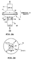
supply system unit 8, thefilter device 10 of the present invention, as shown in Figs. 2A and 2B, comprises two truncatedconical box members filter box 14 having afilter 16 provided in the joined portion between thesebox members inlet side pipe 12 is connected to an inlet port of thebox member 16, on the other hand, anoutlet side pipe 13 is connected to an outlet of thebox member 17. Further, atip part 12a of theinlet side pipe 12 is provided with a protrudedportion 12b on its entire inner periphery, thus forming the tip. - In the
filter box 14, the ink inlet sidefilter box member 16 is disposed beneath the ink outlet sidefilter box member 17 through thefilter 15 so that the ink flow is in a vertical upward direction. That is, in the recording head shown in Fig. 1, the discharge port is used in a vertical downward direction. - Therefore, the
filter box 14 provided with thefilter 15 has a so-called abacus bead form in which two truncatedconical box members filter 15 of a diameter D is integrally formed at the joined portion at the center of thefilter box 14, theinlet side pipe 12 of a diameter d1 is connected at the ink inlet side, and theoutlet side pipe 13 of the same diameter d1 is connected at the ink outlet side. - The walls for these
inlet side pipe 12 andoutlet side pipe 13, thebox members filter box 14 and the like are not shown in the figure, and can be formed in the appropriate thicknesses. Further, when thefilter box 14 is made of a transparent or translucent synthetic resin or the like, it is advantageous for checking the inside state visually. - Specifically, as shown in the figures, the
inlet side pipe 12 and theoutlet side pipe 13 are both made of a pipe having the same diameter d1, further, thetip part 12a of theinlet side pipe 12 is tapered to a diameter d2 at theinlet port 14a into thefilter box 14. That is, the outlet port of thetip part 12a of theinlet side pipe 12 is theinlet port 14a of thefilter box 14, forming an orifice of a diameter d2. Therefore, theinlet port 14a of thefilter box 14 also has a diameter d2. - Since a "constricted" part as shown in the figure is formed at the connection part between the
tip part 12a of theinlet side pipe 12 and theinlet port 14a of thefilter box 14, it is preferable that the protrudedportion 12b is provided on the outer periphery of the constricted part by adhering an appropriate filling material or molding material to approximately to the same diameter as theinlet side pipe 12 so that the strength of this portion is increased. - Further, the
filter box 14 is tapered from theinlet port 14a towards inside thefilter box 14 to form a bell-bottomed shape expanding towards the filter diameter, and after passing thefilter 15 on the contrary, similarly tapered to converge in a bell-bottomed shape towards theoutlet side pipe 13. - In the thus constructed first embodiment of the present invention, the
inlet side pipe 12 having the diameter d1 is tapered down at the connection part with thefilter box 14, diameter of the outlet port of thetapered tip part 12a is the same diameter d2 as that of theinlet port 14a of thefilter box 14, and theinlet side pipe 12 and theoutlet side pipe 13 are the same in diameter, where since thefilter 15 has a diameter of D, there is a relation of D > d1 > d2 among these diameters d1, d2, and D. - In the above-described first embodiment of the ink-jet recording head of the present invention, the
filter device 10 is disposed which has thefilter box 14 provided with thefilter 15 for preventing contamination of fine dust in the passage for supplying the ink to the common liquid chamber of thegrooved ceiling plate 2, the inside diameter d1 of theinlet side pipe 12 at the inlet side of thebox member 16 of thefilter box 14 is narrowed by one step, and at the part before immediately expanding to a bell-bottomed shape towards the diameter of thefilter 15, is formed in an orifice-shape having a diameter d2 at the hole of the outlet port of thetip part 12a. As a result, the flow rate of the ink passing through this part is increased, and it can offset a decrease in flow rate due to the expansion in the bell-bottomed shape towards thefilter 15 having the diameter D to prevent a generation of a bubble due to a stagnation of the ink. Further, by the ink flow increased in flow rate by passing through theinlet port 14a, a turbulent flow of the ink is generated in the interior of thefilter box member 16, even when a bubble adheres to the surface at the ink inlet side of the filter, the bubble is divided into small pieces so that they can pass through the filter and move upward (to the downstream side). - Still further, even when a bubble is generated for some reason, by the above-described increase of the ink flow rate and the generation of a turbulent flow, the bubble can be destructed to flow into the common liquid chamber of the recording head through the
filter 15 to be discharged from the discharge port of the inkdischarge port surface 2a, that is, from the nozzle, thereby it can construct a highly reliable ink-jet recording head without an occurrence of an unstable discharge or an insufficient ink refill. - Here, the inside diameter d1 of the
ink inlet pipe 12 can be determined so that an ink supply failure is not generated to the head when the ink flow rate is a maximum, and the filter diameter is a minimum in view of a down-sizing of the apparatus itself. The maximum value of the ink flow rate can be calculated from the number of the discharge ports of the recording head, the ink discharge amount from the discharge port, the driving frequency and the like, and when the respective values are increased, the maximum value of the ink flow rate is required to be estimated at a large value. In the case of the present embodiment of a so-called full-line type recording head which has a large number of discharge ports (actually 300 or more), since the driving frequency is about 2 to 5 (KHz) which is not so high, according to an experiment conducted by the inventors, it has been confirmed that the above-described insufficient supply is not generated when the diameter d1 ≧ 10 (mm). - Yet further, as to the tapered shape of the
tip part 12a of the inlet pipe, since a loss coefficient ζ due to a rapid reduction loss is increased if it has a stepped shape, it is desirable that the tapered shape be such that the sectional area continuously decreases with respect to the ink flow direction (vertical upward). Then, the inventors have determined the inner surface shape of thetip part 12a to be approximately a truncated conical shape, where an angle is between the part of continuously changing cross-sectional shape and the inside wall of the ink flow passage, investigated an optimum range of the angle and obtained the result shown in Table 1 below.Sample d1 (mm) d2 (mm) (deg.) Presence of remaining bubble 1 10 5 10 X 2 10 5 20 X 3 10 5 30 ○ 4 10 5 40 ○ 5 10 5 45 ○ 6 10 5 50 X - From Table 1, it has been confirmed that in the case of the angle 30° ≦ ≦ 45°, the above effect be provided without reducing the effect by the increased flow rate, and without finding a phenomenon of the reduction in the flow rate because this part acts as a resistance.
- Further, as to the relation between the diameters d1 and d2, although depending on the magnitude of the inside diameter d1, when the investigation has been conducted on the condition to divide the bubble formed on the filter into smallest sizes under the conditions of the diameter d1 = 10 mm, the angle 30° ≦ ≦ 45°, the results shown in Table 2 have been obtained.
Sample d1 (mm) d2 (mm) Presence of remaining bubble 1 10 10 X 2 10 8 X 3 10 5 ○ 4 10 3 ○ 5 10 2.5 ○ 6 10 2 X - As can be seen from Table 2, it has been confirmed that the remaining bubble on the filter be finely divided in the range of the ratio of the
diameters 2 ≦ d1/d2 ≦ 4. In the case of the present embodiment, in particular, according to an experiment by the inventors, it has been found that the bubble has divided into the smallest sizes at the time of the diameter d1 = 2d2. - As to the range of the above angle , the range of the angle 30° ≦ ≦ 45° can provide the above effect without being affected by the respective diameters when the diameters d1 and d2 meet the above desirable relation.
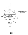
- Fig. 3 illustrates a second embodiment of the ink-jet recording apparatus according to the present invention, of which the basic construction of an
inlet side pipe 22, anoutlet side pipe 23, afilter 25 and the like is the same as in the first embodiment. In the second embodiment, atop surface 26b of the inletside box member 26 of afilter box 24 is broad and flat, and aninlet port 26a is provided at the center to form an orifice. - Consequently, the constricted part on the periphery of the part joining the
tip part 22a of theinlet side pipe 22 with thetop surface 26b of thebox member 26 is provided with aprotruded part 22b by adhering an appropriate filling material or molding material to make the outer peripheral surface in flat. - Also in the thus constructed second embodiment of the present invention, as in the first embodiment, since the inside diameter d1 of the
inlet side pipe 22 to the ink inletside box member 26 of thefilter box 24 is reduced by one step, immediately before expanding into a bell-bottomed shape towards the outer diameter of thefilter 25, that is, forming an orifice shape having a diameter d2 at the hole of the outlet port of thetip part 22a, thus the flow rate of the ink passing this part is increased. Further, the ink flow rate is relaxed in thebox member 26 having a cross-sectional area sharply changing by expanding into the bell-bottomed shape towards thefilter 25 having a diameter D to offset with each other, thereby preventing generation of a bubble due to a stagnation of the ink. - Still further, even when a bubble is generated, since, by the above increased ink flow rate, the bubble is divided to flow the ink into the common liquid chamber of the recording head through the
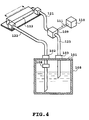
filter 25, and the ink is discharged from the ink discharge port, thereby a highly reliable ink-jet recording head can be obtained without an occurrence of an unstable discharge or an insufficient ink refill. - Fig. 4 illustrates a third embodiment of the ink-jet recording apparatus of the present invention. In the present embodiment, unlike the above first and second embodiments, the above-described filter device is provided in a replaceable ink tank, rather than the recording head.
- In Fig. 4, numeral 108 denotes an ink tank as an ink containing part, which is provided with an
atmosphere communicating hole 101 for communicating with the atmosphere and anink supply port 102 for conducting the ink to the outside. 103 is an ink inlet port for introducing a recirculated ink. 109 is a pump for pumping the ink, 110 is a power supply for driving the pump, and 111 is a switch for controlling the drive. Normally, the ink blows from the ink tank, passing through thefilter device 106 of the present invention and through anink supply passage 122 to thehead 112. During a recovery operation such as a bubble elimination, the ink is recirculated by pumping from the head through anink supply passage 121 as an ink return passage to the ink tank. - Also in such an ink supply path, by applying the filter of the present invention, the same effect as in the above first and second embodiments can be provided. In this case, it is needless to say that the specification of the more preferable range of the angle , and the diameters d1 and d2 described in the above embodiments can also be applied to the present embodiment.
- The present invention achieves distinct effects when applied to a recording head or a recording apparatus which has means for generating thermal energy such as electrothermal transducers or laser light, and which causes changes in ink by the thermal energy so as to eject ink. This is because such a system can achieve a high density and high resolution recording.
- A typical structure and operational principle thereof is disclosed in U.S. patent Nos. 4,723,129 and 4,740,796, and it is preferable to use this basic principle to implement such a system. Although this system can be applied to either on-demand type or continuous type ink jet recording systems, it is particularly suitable for the on-demand type apparatus. This is because the on-demand type apparatus has electrothermal transducers, each disposed on a sheet or liquid passage that retains liquid (ink), and operates as follows: first, one or more drive signals are applied to the electrothermal transducers to cause thermal energy corresponding to recording information; second, the thermal energy induces sudden temperature rise that exceeds the nucleate boiling so as to cause the film boiling on heating portions of the recording head; and third, bubbles are grown in the liquid (ink) corresponding to the drive signals. By using the growth and collapse of the bubbles, the ink is expelled from at least one of the ink ejection orifices of the head to form one or more ink drops. The drive signal in the form of a pulse is preferable because the growth and collapse of the bubbles can be achieved instantaneously and suitably by this form of drive signal. As a drive signal in the form of a pulse, those described in U.S. patent Nos. 4,463,359 and 4,345,262 are preferable. In addition, it is preferable that the rate of temperature rise of the heating portions described in U.S. patent No. 4,313,124 be adopted to achieve better recording.
- U.S. patent Nos. 4,558,333 and 4,459,600 disclose the following structure of a recording head, which is incorporated to the present invention: this structure includes heating portions disposed on bent portions in addition to a combination of the ejection orifices, liquid passages and the electrothermal transducers disclosed in the above patents. Moreover, the present invention can be applied to structures disclosed in Japanese Patent Application Laying-open Nos. 59-123670 (1984) and 59-138461 (1984) in order to achieve similar effects. The former discloses a structure in which a slit common to all the electrothermal transducers is used as ejection orifices of the electrothermal transducers, and the latter discloses a structure in which openings for absorbing pressure waves caused by thermal energy are formed corresponding to the ejection orifices. Thus, irrespective of the type of the recording head, the present invention can achieve recording positively and effectively.
- The present invention can be also applied to a so-called full-line type recording head whose length equals the maximum length across a recording medium. Such a recording head may consists of a plurality of recording heads combined together, or one integrally arranged recording head.
- In addition, the present invention can be applied to various serial type recording heads: a recording head fixed to the main assembly of a recording apparatus; a conveniently replaceable chip type recording head which, when loaded on the main assembly of a recording apparatus, is electrically connected to the main assembly, and is supplied with ink therefrom; and a cartridge type recording head integrally including an ink reservoir.
- It is further preferable to add a recovery system, or a preliminary auxiliary system for a recording head as a constituent of the recording apparatus because they serve to make the effect of the present invention more reliable. Examples of the recovery system are a capping means and a cleaning means for the recording head, and a pressure or suction means for the recording head. Examples of the preliminary auxiliary system are a preliminary heating means utilizing electrothermal transducers or a combination of other heater elements and the electrothermal transducers, and a means for carrying out preliminary ejection of ink independently of the ejection for recording. These systems are effective for reliable recording.
- The number and type of recording heads to be mounted on a recording apparatus can be also changed. For example, only one recording head corresponding to a single color ink, or a plurality of recording heads corresponding to a plurality of inks different in color or concentration can be used. In other words, the present invention can be effectively applied to an apparatus having at least one of the monochromatic, multi-color and full-color modes. Here, the monochromatic mode performs recording by using only one major color such as black. The multi-color mode carries out recording by using different color inks, and the full-color mode performs recording by color mixing.
- Furthermore, although the above-described embodiments use liquid ink, inks that are liquid when the recording signal is applied can be used: for example, inks can be employed that solidify at a temperature lower than the room temperature and are softened or liquefied in the room temperature. This is because in the ink jet system, the ink is generally temperature adjusted in a range of the temperature 30° - 70° so that the viscosity of the ink is maintained at such a value that the ink can be ejected reliably.
- In addition, the present invention can be applied to such apparatus where the ink is liquefied just before the ejection by the thermal energy as follows so that the ink is expelled from the orifices in the liquid state, and then begins to solidify on hitting the recording medium, thereby preventing the ink evaporation: the ink is transformed from solid to liquid state by positively utilizing the thermal energy which would otherwise cause the temperature rise; or the ink, which is dry when left in air, is liquefied in response to the thermal energy of the recording signal. In such cases, the ink may be retained in recesses or through holes formed in a porous sheet as liquid or solid substances so that the ink faces to the electrothermal transducers as described in Japanese Patent Application Laying-open Nos. 54-56847 (1979) or 60-71260 (1985). The present invention is most effective when it uses the film boiling phenomenon to expel the ink.
- Furthermore, the ink jet recording apparatus of the present invention can be employed not only as an image output terminal of an information processing device such as a computer, but also as an output device of a copying machine including a reader, and as an output device of a facsimile apparatus having a transmission and receiving function.
- The present invention has been described in detail with respect to various embodiments, and it will now be apparent from the foregoing to those skilled in the art that changes and modifications may be made without departing from the invention in its broader aspects, and it is the intention, therefore, in the appended claims to cover all such changes and modifications as fall within the true spirit of the invention.
- An adhering of an ink bubble to a filter causes a decreasing of an effective area of the filter, a disturbance of an ink refill and an unstable discharge or discharge failure. An ink supply device (8) having an ink flow passage (7) for communicating an ink containing part for containing an ink with a discharge part (2a) for discharging the ink, the ink flow passage (7) is characterized by a filter device (10) including a filter (15) and a filter box (14) for containing the filter (15) and provided with an ink inlet port (12) and an ink outlet port (13), wherein an area at the ink inlet port (12) side of the filter box (14) is disposed beneath an area at the ink outlet port (13) side of the filter box (14), and an inside diameter (d2) of ink flow passage (12a) at the ink inlet port (12) side of the filter box (14) is narrowed in a diameter to be smaller than an inside diameter (d1) of the ink flow passage (12) immediately before expanding into a bell-bottomed shape towards the filter (15).
Claims (9)
- An ink supply device having an ink flow passage for communicating an ink containing part for containing an ink with a discharge part for discharging said ink, said ink flow passage is characterized by a filter device including a filter and a filter box for containing said filter and provided with an ink inlet port and an ink outlet port, characterized in thatan area at the ink inlet port side of said filter box is disposed beneath an area at the ink outlet port side of said filter box, andan inside diameter of ink flow passage at the ink inlet port side of said filter box is narrowed in a diameter to be smaller than an inside diameter of said ink flow passage immediately before expanding into a bell-bottomed shape towards said filter.
- The ink supply device as claimed in Claim 1, characterized in that an inside diameter d1 of ink inlet side flow passage of said filter box, an inside diameter d2 of a part narrowed in diameter by one step of said flow passage, and a filter outside diameter D have a dimensional relation of the diameters D > d1 > d2.
- The ink supply device as claimed in Claim 2, characterized in that the inside diameter d1 of said ink inlet side flow passage and the inside diameter d2 of the part of said flow passage narrowed diametrally by one step satisfy a ratio of the diameters 2 ≦ d1/d2 ≦ 4.
- The ink supply device as claimed in Claim 1, characterized in that said one step narrowed part of ink flow passage has changed a cross-sectional shape continuously.
- The ink supply device as claimed in Claim 4, characterized in that an angle between said part continuously changing in cross-sectional shape and an inside wall of said ink flow passage satisfies an angle 30° ≦ ≦ 45°.
- An ink-jet recording head for discharging an ink comprising a filter device having a filter and a filter box provided for each of the ink inlet side and the ink outlet side with respect to said filter, characterized in thatsaid ink inlet side filter box is disposed beneath said ink outlet side filter box through the filter, andan inside diameter of ink flow passage at the ink inlet side of said filter box is narrowed in diameter to be smaller than said inside diameter of ink flow passage immediately before expanding into a bell-bottomed shape towards said filter.
- The ink-jet recording head as claimed in Claim 6, characterized in that said ink-jet recording head comprises a discharge port formation member having a discharge port, an ink flow passage communicating with said discharge port, a common liquid chamber at the rear end of said ink flow passage, and a discharge energy generation element disposed in a part of said ink flow passage for generating a thermal energy utilized for discharging an ink to generate a bubble for discharging the ink, whereby forming flying liquid drops for performing recording.
- The ink-jet recording head as claimed in Claim 6, characterized in that said filter box is made of a transparent material.
- The ink-jet recording head as claimed in Claim 6, characterized in that said filter box is made from two truncated conical box members joined opposing the cone surface sides provided with the filter.
Applications Claiming Priority (4)
| Application Number | Priority Date | Filing Date | Title |
|---|---|---|---|
| JP16989198 | 1998-06-17 | ||
| JP16989198 | 1998-06-17 | ||
| JP11150508A JP2000071477A (en) | 1998-06-17 | 1999-05-28 | Ink supplying device and ink jet recording head |
| JP15050899 | 1999-05-28 |
Publications (2)
| Publication Number | Publication Date |
|---|---|
| EP0965452A1 true EP0965452A1 (en) | 1999-12-22 |
| EP0965452B1 EP0965452B1 (en) | 2003-01-15 |
Family
ID=26480077
Family Applications (1)
| Application Number | Title | Priority Date | Filing Date |
|---|---|---|---|
| EP99111675A Expired - Lifetime EP0965452B1 (en) | 1998-06-17 | 1999-06-16 | Ink supply device and ink-jet recording head |
Country Status (4)
| Country | Link |
|---|---|
| US (1) | US6250752B1 (en) |
| EP (1) | EP0965452B1 (en) |
| JP (1) | JP2000071477A (en) |
| DE (1) | DE69904876T2 (en) |
Cited By (7)
| Publication number | Priority date | Publication date | Assignee | Title |
|---|---|---|---|---|
| EP1403063A1 (en) * | 2002-09-25 | 2004-03-31 | Brother Kogyo Kabushiki Kaisha | Ink-jet head, filter assembly used for manufacturing the ink-jet head, and method for manufacturing the ink-jet head using the filter assembly |
| US6739706B2 (en) | 2002-04-19 | 2004-05-25 | Hewlett-Packard Development Company, L.P. | Off axis inkjet printing system and method |
| US6752493B2 (en) | 2002-04-30 | 2004-06-22 | Hewlett-Packard Development Company, L.P. | Fluid delivery techniques with improved reliability |
| WO2005007415A3 (en) * | 2003-07-16 | 2005-04-14 | Xaar Technology Ltd | Droplet deposition apparatus |
| US6955425B2 (en) | 2002-04-26 | 2005-10-18 | Hewlett-Packard Development Company, L.P. | Re-circulating fluid delivery systems |
| US7575309B2 (en) | 2005-02-24 | 2009-08-18 | Hewlett-Packard Development Company, L.P. | Fluid supply system |
| EP2305470A1 (en) * | 2009-10-02 | 2011-04-06 | Hitachi Industrial Equipment Systems Co., Ltd. | Inkjet printer and filter for an inkjet printer |
Families Citing this family (26)
| Publication number | Priority date | Publication date | Assignee | Title |
|---|---|---|---|---|
| CN1162276C (en) * | 1999-10-06 | 2004-08-18 | 精工爱普生株式会社 | Ink-jet printer possessing connecting unit for automatically removing air bubble collected in filter |
| JP3801003B2 (en) | 2001-02-09 | 2006-07-26 | キヤノン株式会社 | Liquid supply system, ink jet recording head, and liquid filling method |
| JP4593063B2 (en) * | 2002-08-27 | 2010-12-08 | エスアイアイ・プリンテック株式会社 | Inkjet recording device |
| US7159974B2 (en) * | 2003-10-06 | 2007-01-09 | Lexmark International, Inc. | Semipermeable membrane for an ink reservoir and method of attaching the same |
| JP4726501B2 (en) * | 2005-01-21 | 2011-07-20 | キヤノンファインテック株式会社 | Inkjet recording head and inkjet recording apparatus |
| JP4853191B2 (en) * | 2006-09-06 | 2012-01-11 | セイコーエプソン株式会社 | Liquid jet head |
| JP4823038B2 (en) * | 2006-12-06 | 2011-11-24 | キヤノン株式会社 | Ink jet head cartridge, recording head, ink storage container, and method of manufacturing ink jet head cartridge |
| JP5446176B2 (en) * | 2008-09-02 | 2014-03-19 | セイコーエプソン株式会社 | Liquid ejector |
| US20100053286A1 (en) * | 2008-09-02 | 2010-03-04 | Seiko Epson Corporation | Liquid supply device and liquid ejecting apparatus |
| JP2012121168A (en) * | 2010-12-06 | 2012-06-28 | Canon Inc | Liquid ejection head, and method of producing the same |
| US8371684B2 (en) * | 2011-01-31 | 2013-02-12 | Videojet Technologies Inc. | Ink mixing system |
| US8696098B2 (en) | 2011-12-09 | 2014-04-15 | Xerox Corporation | Printhead having particle circulation with separation |
| JP6078301B2 (en) * | 2012-11-07 | 2017-02-08 | 株式会社ミマキエンジニアリング | Damper device and inkjet printer |
| US9168740B2 (en) * | 2013-04-11 | 2015-10-27 | Eastman Kodak Company | Printhead including acoustic dampening structure |
| US9162454B2 (en) * | 2013-04-11 | 2015-10-20 | Eastman Kodak Company | Printhead including acoustic dampening structure |
| JP6611618B2 (en) | 2016-01-08 | 2019-11-27 | キヤノン株式会社 | Recording apparatus, recording apparatus control method, and program |
| US9925791B2 (en) | 2016-01-08 | 2018-03-27 | Canon Kabushiki Kaisha | Liquid ejection apparatus and liquid ejection head |
| JP6716258B2 (en) | 2016-01-08 | 2020-07-01 | キヤノン株式会社 | Recording device, recording device control method, and program |
| US10005287B2 (en) | 2016-01-08 | 2018-06-26 | Canon Kabushiki Kaisha | Liquid ejection apparatus, liquid ejection head, and method of supplying liquid |
| US9914308B2 (en) | 2016-01-08 | 2018-03-13 | Canon Kabushiki Kaisha | Liquid ejection apparatus and liquid ejection head |
| JP6638442B2 (en) * | 2016-02-09 | 2020-01-29 | セイコーエプソン株式会社 | Liquid container, liquid ejecting apparatus, and maintenance method for liquid ejecting apparatus |
| JP2017209864A (en) | 2016-05-25 | 2017-11-30 | キヤノン株式会社 | Liquid discharge device and liquid discharge head |
| JP7246978B2 (en) | 2019-03-15 | 2023-03-28 | キヤノン株式会社 | Liquid ejection device and liquid filling method |
| JP7391637B2 (en) | 2019-12-03 | 2023-12-05 | キヤノン株式会社 | Liquid storage device and liquid filling method |
| JP7527826B2 (en) | 2020-03-31 | 2024-08-05 | キヤノン株式会社 | Recording device |
| CN114536985A (en) * | 2022-02-10 | 2022-05-27 | 深圳市华星光电半导体显示技术有限公司 | Ink container and ink jet printing apparatus |
Citations (4)
| Publication number | Priority date | Publication date | Assignee | Title |
|---|---|---|---|---|
| EP0596252A1 (en) * | 1992-10-02 | 1994-05-11 | Canon Kabushiki Kaisha | Ink supply mechanism, ink jet cartridge provided with such a mechanism, and ink jet recording apparatus provided with such a mechanism |
| EP0609863A2 (en) * | 1993-02-02 | 1994-08-10 | Seiko Epson Corporation | Method of filling ink in ink supply passages and ink-jet recording apparatus |
| EP0683050A2 (en) * | 1994-05-20 | 1995-11-22 | Canon Kabushiki Kaisha | Ink supplying apparatus and ink jet recording apparatus having same |
| DE19613654A1 (en) * | 1995-04-05 | 1996-10-10 | Seiko Epson Corp | Ink jet recording device |
Family Cites Families (19)
| Publication number | Priority date | Publication date | Assignee | Title |
|---|---|---|---|---|
| CA1127227A (en) | 1977-10-03 | 1982-07-06 | Ichiro Endo | Liquid jet recording process and apparatus therefor |
| JPS5936879B2 (en) | 1977-10-14 | 1984-09-06 | キヤノン株式会社 | Thermal transfer recording medium |
| US4330787A (en) | 1978-10-31 | 1982-05-18 | Canon Kabushiki Kaisha | Liquid jet recording device |
| US4345262A (en) | 1979-02-19 | 1982-08-17 | Canon Kabushiki Kaisha | Ink jet recording method |
| US4463359A (en) | 1979-04-02 | 1984-07-31 | Canon Kabushiki Kaisha | Droplet generating method and apparatus thereof |
| US4313124A (en) | 1979-05-18 | 1982-01-26 | Canon Kabushiki Kaisha | Liquid jet recording process and liquid jet recording head |
| US4320407A (en) * | 1980-05-19 | 1982-03-16 | Burroughs Corporation | Fluid pump system for an ink jet printer |
| US4558333A (en) | 1981-07-09 | 1985-12-10 | Canon Kabushiki Kaisha | Liquid jet recording head |
| JPS59123670A (en) | 1982-12-28 | 1984-07-17 | Canon Inc | Ink jet head |
| JPS59138461A (en) | 1983-01-28 | 1984-08-08 | Canon Inc | Liquid jet recording apparatus |
| JPS6071260A (en) | 1983-09-28 | 1985-04-23 | Erumu:Kk | Recorder |
| US4931811A (en) * | 1989-01-31 | 1990-06-05 | Hewlett-Packard Company | Thermal ink jet pen having a feedtube with improved sizing and operational with a minimum of depriming |
| JPH02204044A (en) | 1989-02-03 | 1990-08-14 | Canon Inc | Ink jet head |
| DE69031872T2 (en) | 1989-09-18 | 1998-04-30 | Canon Kk | Method of filling an ink cartridge for ink jet recorders |
| GB2236847A (en) | 1989-10-14 | 1991-04-17 | Ferranti Int Signal | Incremental position transducer |
| JP3225072B2 (en) | 1992-01-24 | 2001-11-05 | 東芝テック株式会社 | External rotation type long thin motor |
| JPH05207714A (en) | 1992-01-27 | 1993-08-13 | Matsushita Seiko Co Ltd | Rotor for induction motor |
| JP3148005B2 (en) | 1992-06-16 | 2001-03-19 | キヤノン株式会社 | Recording cartridge and ink jet recording apparatus |
| GB2326845B (en) | 1995-04-05 | 1999-05-26 | Seiko Epson Corp | Ink-jet recording apparatus |
-
1999
- 1999-05-28 JP JP11150508A patent/JP2000071477A/en active Pending
- 1999-06-11 US US09/330,026 patent/US6250752B1/en not_active Expired - Fee Related
- 1999-06-16 DE DE69904876T patent/DE69904876T2/en not_active Expired - Fee Related
- 1999-06-16 EP EP99111675A patent/EP0965452B1/en not_active Expired - Lifetime
Patent Citations (4)
| Publication number | Priority date | Publication date | Assignee | Title |
|---|---|---|---|---|
| EP0596252A1 (en) * | 1992-10-02 | 1994-05-11 | Canon Kabushiki Kaisha | Ink supply mechanism, ink jet cartridge provided with such a mechanism, and ink jet recording apparatus provided with such a mechanism |
| EP0609863A2 (en) * | 1993-02-02 | 1994-08-10 | Seiko Epson Corporation | Method of filling ink in ink supply passages and ink-jet recording apparatus |
| EP0683050A2 (en) * | 1994-05-20 | 1995-11-22 | Canon Kabushiki Kaisha | Ink supplying apparatus and ink jet recording apparatus having same |
| DE19613654A1 (en) * | 1995-04-05 | 1996-10-10 | Seiko Epson Corp | Ink jet recording device |
Cited By (12)
| Publication number | Priority date | Publication date | Assignee | Title |
|---|---|---|---|---|
| US6739706B2 (en) | 2002-04-19 | 2004-05-25 | Hewlett-Packard Development Company, L.P. | Off axis inkjet printing system and method |
| US6955425B2 (en) | 2002-04-26 | 2005-10-18 | Hewlett-Packard Development Company, L.P. | Re-circulating fluid delivery systems |
| US7497562B2 (en) | 2002-04-26 | 2009-03-03 | Hewlett-Packard Development Company, L.P. | Re-circulating fluid delivery systems |
| US6752493B2 (en) | 2002-04-30 | 2004-06-22 | Hewlett-Packard Development Company, L.P. | Fluid delivery techniques with improved reliability |
| EP1403063A1 (en) * | 2002-09-25 | 2004-03-31 | Brother Kogyo Kabushiki Kaisha | Ink-jet head, filter assembly used for manufacturing the ink-jet head, and method for manufacturing the ink-jet head using the filter assembly |
| US7044591B2 (en) | 2002-09-25 | 2006-05-16 | Brother Kogya Kabushiki Kaisha | Ink-jet head, filter assembly used for manufacturing the ink-jet head, and method for manufacturing the ink-jet head using the filter assembly |
| US7753513B2 (en) | 2002-09-25 | 2010-07-13 | Brother Kogyo Kabushiki Kaisha | Ink-jet head, filter assembly used for manufacturing the ink-jet head, and method for manufacturing the ink-jet head using the filter assembly |
| WO2005007415A3 (en) * | 2003-07-16 | 2005-04-14 | Xaar Technology Ltd | Droplet deposition apparatus |
| US7806515B2 (en) | 2003-07-16 | 2010-10-05 | Xaar Technology Limited | Droplet deposition apparatus |
| US7575309B2 (en) | 2005-02-24 | 2009-08-18 | Hewlett-Packard Development Company, L.P. | Fluid supply system |
| US8182076B2 (en) | 2005-02-24 | 2012-05-22 | Hewlett-Packard Development Company, L.P. | Fluid supply system |
| EP2305470A1 (en) * | 2009-10-02 | 2011-04-06 | Hitachi Industrial Equipment Systems Co., Ltd. | Inkjet printer and filter for an inkjet printer |
Also Published As
| Publication number | Publication date |
|---|---|
| US6250752B1 (en) | 2001-06-26 |
| EP0965452B1 (en) | 2003-01-15 |
| JP2000071477A (en) | 2000-03-07 |
| DE69904876T2 (en) | 2003-11-20 |
| DE69904876D1 (en) | 2003-02-20 |
Similar Documents
| Publication | Publication Date | Title |
|---|---|---|
| EP0965452B1 (en) | Ink supply device and ink-jet recording head | |
| US4727378A (en) | Method and apparatus for purging an ink jet head | |
| US5457485A (en) | Ink jet recording apparatus | |
| EP0645244A1 (en) | Ink jet head and ink jet recording apparatus having same | |
| US20020063763A1 (en) | Apparatus and method for removing air bubbles from an ink jet printhead | |
| JP5058719B2 (en) | Liquid discharge head and ink jet recording apparatus | |
| EP0252676A2 (en) | Air assisted ink jet head with single compartment ink chamber | |
| US6267251B1 (en) | Filter assembly for a print cartridge container for removing contaminants from a fluid | |
| JP2005231364A (en) | Apparatus for using bubble as virtual valve in microinjector to inject liquid | |
| US6637874B2 (en) | Liquid ejecting head, suction recovering method, head cartridge and image forming apparatus | |
| JPH09226142A (en) | Ink jet printer and ink jet print head | |
| JPH1029311A (en) | Thermal ink jet printing head | |
| US6109744A (en) | Asymmetric restrictor for ink jet printhead | |
| JP3581504B2 (en) | Inkjet print head | |
| JPS6135254A (en) | Recording head for ink jet recorder | |
| JP2009511293A (en) | Low loss electrode connection for inkjet printheads | |
| EP1078756B1 (en) | Ink jet recording head, ink jet recording head cartridge and ink jet recording apparatus | |
| JP2936358B2 (en) | Driving method of inkjet print head | |
| JPH0820111A (en) | Liquid jet recording head, and liquid jet recording apparatus carrying the recording head | |
| US6000777A (en) | Ink jet recording head, ink jet recording apparatus, and information processing system | |
| JPH07195711A (en) | Ink jet recording apparatus | |
| JPS60139457A (en) | Ink jet print head | |
| JPH024519A (en) | Ink jet recording head | |
| JPH0789098A (en) | Ink jet recorder | |
| JPH11170530A (en) | Ink jet print head, ink jet printing device and manufacture thereof |
Legal Events
| Date | Code | Title | Description |
|---|---|---|---|
| PUAI | Public reference made under article 153(3) epc to a published international application that has entered the european phase |
Free format text: ORIGINAL CODE: 0009012 |
|
| AK | Designated contracting states |
Kind code of ref document: A1 Designated state(s): DE FR GB IT |
|
| AX | Request for extension of the european patent |
Free format text: AL;LT;LV;MK;RO;SI |
|
| 17P | Request for examination filed |
Effective date: 20000508 |
|
| AKX | Designation fees paid |
Free format text: DE FR GB IT |
|
| 17Q | First examination report despatched |
Effective date: 20010517 |
|
| GRAG | Despatch of communication of intention to grant |
Free format text: ORIGINAL CODE: EPIDOS AGRA |
|
| GRAG | Despatch of communication of intention to grant |
Free format text: ORIGINAL CODE: EPIDOS AGRA |
|
| GRAH | Despatch of communication of intention to grant a patent |
Free format text: ORIGINAL CODE: EPIDOS IGRA |
|
| GRAH | Despatch of communication of intention to grant a patent |
Free format text: ORIGINAL CODE: EPIDOS IGRA |
|
| GRAA | (expected) grant |
Free format text: ORIGINAL CODE: 0009210 |
|
| AK | Designated contracting states |
Kind code of ref document: B1 Designated state(s): DE FR GB IT |
|
| REG | Reference to a national code |
Ref country code: GB Ref legal event code: FG4D |
|
| REF | Corresponds to: |
Ref document number: 69904876 Country of ref document: DE Date of ref document: 20030220 Kind code of ref document: P |
|
| ET | Fr: translation filed | ||
| PLBE | No opposition filed within time limit |
Free format text: ORIGINAL CODE: 0009261 |
|
| STAA | Information on the status of an ep patent application or granted ep patent |
Free format text: STATUS: NO OPPOSITION FILED WITHIN TIME LIMIT |
|
| 26N | No opposition filed |
Effective date: 20031016 |
|
| PGFP | Annual fee paid to national office [announced via postgrant information from national office to epo] |
Ref country code: IT Payment date: 20080621 Year of fee payment: 10 |
|
| PGFP | Annual fee paid to national office [announced via postgrant information from national office to epo] |
Ref country code: DE Payment date: 20080630 Year of fee payment: 10 |
|
| PGFP | Annual fee paid to national office [announced via postgrant information from national office to epo] |
Ref country code: FR Payment date: 20080625 Year of fee payment: 10 |
|
| PGFP | Annual fee paid to national office [announced via postgrant information from national office to epo] |
Ref country code: GB Payment date: 20080627 Year of fee payment: 10 |
|
| GBPC | Gb: european patent ceased through non-payment of renewal fee |
Effective date: 20090616 |
|
| REG | Reference to a national code |
Ref country code: FR Ref legal event code: ST Effective date: 20100226 |
|
| PG25 | Lapsed in a contracting state [announced via postgrant information from national office to epo] |
Ref country code: FR Free format text: LAPSE BECAUSE OF NON-PAYMENT OF DUE FEES Effective date: 20090630 |
|
| PG25 | Lapsed in a contracting state [announced via postgrant information from national office to epo] |
Ref country code: GB Free format text: LAPSE BECAUSE OF NON-PAYMENT OF DUE FEES Effective date: 20090616 |
|
| PG25 | Lapsed in a contracting state [announced via postgrant information from national office to epo] |
Ref country code: DE Free format text: LAPSE BECAUSE OF NON-PAYMENT OF DUE FEES Effective date: 20100101 |
|
| PG25 | Lapsed in a contracting state [announced via postgrant information from national office to epo] |
Ref country code: IT Free format text: LAPSE BECAUSE OF NON-PAYMENT OF DUE FEES Effective date: 20090616 |