EP0965373A1 - Destillationsanlage mit Kolonne und Wärmepumpe. - Google Patents
Destillationsanlage mit Kolonne und Wärmepumpe. Download PDFInfo
- Publication number
- EP0965373A1 EP0965373A1 EP99810436A EP99810436A EP0965373A1 EP 0965373 A1 EP0965373 A1 EP 0965373A1 EP 99810436 A EP99810436 A EP 99810436A EP 99810436 A EP99810436 A EP 99810436A EP 0965373 A1 EP0965373 A1 EP 0965373A1
- Authority
- EP
- European Patent Office
- Prior art keywords
- heat pump
- distillation plant
- plant according
- compressor
- heat
- Prior art date
- Legal status (The legal status is an assumption and is not a legal conclusion. Google has not performed a legal analysis and makes no representation as to the accuracy of the status listed.)
- Granted
Links
Images

Classifications
-
- F—MECHANICAL ENGINEERING; LIGHTING; HEATING; WEAPONS; BLASTING
- F25—REFRIGERATION OR COOLING; COMBINED HEATING AND REFRIGERATION SYSTEMS; HEAT PUMP SYSTEMS; MANUFACTURE OR STORAGE OF ICE; LIQUEFACTION SOLIDIFICATION OF GASES
- F25B—REFRIGERATION MACHINES, PLANTS OR SYSTEMS; COMBINED HEATING AND REFRIGERATION SYSTEMS; HEAT PUMP SYSTEMS
- F25B1/00—Compression machines, plants or systems with non-reversible cycle
- F25B1/06—Compression machines, plants or systems with non-reversible cycle with compressor of jet type, e.g. using liquid under pressure
-
- B—PERFORMING OPERATIONS; TRANSPORTING
- B01—PHYSICAL OR CHEMICAL PROCESSES OR APPARATUS IN GENERAL
- B01D—SEPARATION
- B01D3/00—Distillation or related exchange processes in which liquids are contacted with gaseous media, e.g. stripping
- B01D3/007—Energy recuperation; Heat pumps
-
- B—PERFORMING OPERATIONS; TRANSPORTING
- B01—PHYSICAL OR CHEMICAL PROCESSES OR APPARATUS IN GENERAL
- B01D—SEPARATION
- B01D3/00—Distillation or related exchange processes in which liquids are contacted with gaseous media, e.g. stripping
- B01D3/14—Fractional distillation or use of a fractionation or rectification column
-
- Y—GENERAL TAGGING OF NEW TECHNOLOGICAL DEVELOPMENTS; GENERAL TAGGING OF CROSS-SECTIONAL TECHNOLOGIES SPANNING OVER SEVERAL SECTIONS OF THE IPC; TECHNICAL SUBJECTS COVERED BY FORMER USPC CROSS-REFERENCE ART COLLECTIONS [XRACs] AND DIGESTS
- Y02—TECHNOLOGIES OR APPLICATIONS FOR MITIGATION OR ADAPTATION AGAINST CLIMATE CHANGE
- Y02B—CLIMATE CHANGE MITIGATION TECHNOLOGIES RELATED TO BUILDINGS, e.g. HOUSING, HOUSE APPLIANCES OR RELATED END-USER APPLICATIONS
- Y02B30/00—Energy efficient heating, ventilation or air conditioning [HVAC]
- Y02B30/52—Heat recovery pumps, i.e. heat pump based systems or units able to transfer the thermal energy from one area of the premises or part of the facilities to a different one, improving the overall efficiency
Definitions
- the invention relates to a distillation plant with a column and a heat pump according to the preamble of claim 1 and uses of the system.
- Vapors (often called vapors) dissipate an appropriate amount of heat becomes.
- the supply of heat in the swamp and the removal of heat in the head are advantageously coupled via a heat pump process by means of which a heat transfer as well as heat change (i.e. increasing the temperature of the transported heat) is feasible.
- the distillation plant comprises a column and one between one Bottom evaporator and a vapor condenser of the column working Heat pump.
- the heat pump can be replaced by devices that can be connected to the bottom evaporator and the vapor condenser if necessary are.
- These substituting facilities include facilities for Generation of steam or to provide a coolant and Connection means.
- the coolants can be liquids (water) or gases Be (air).
- the dependent claims 2 to 6 relate to advantageous Embodiments of the distillation plant according to the invention.
- the subject of claims 7 to 10 is the use of this system.
- the raw product F which is already produced by supplying heat in the subsystem 20 can be preheated, in a heat exchanger 100 from one at the Distillation obtained bottom product P 'further heat before it is fed into column 1.
- styrene can be made from a mixture win that the lower boiling ethylbenzene and in smaller quantities Contains toluene and benzene.
- the high-boiling styrene can in the evaporator 3 be heated with steam of 104 ° C (pressure 1170 mbar) so that it is evaporable in the sump 11 at a temperature of 100 ° C.
- the brothers in Head 12 with a temperature of 82 ° C can be in the condenser 2 Liquefy condensed water at 77 ° C (vapor pressure 416mbar).
- the Compressor 4 needs water vapor from the bottom 21 of the vapor condenser Compress 2 from 416 to 1170 mbar.
- a control device is advantageously provided (not shown) by means of a switch from the heat pump to the substitute Facilities can be run as soon as there is a failure of the Compressor 4 is coming.
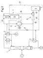
- the device 6 for generating steam is usually a boiler that Emits steam of, for example, 6 or 16 bar. It is therefore a Pressure relief device in the connection means 63 'between the boiler 6 and Bottom evaporator 3 to be arranged. It is possible to have one Pressure relief device as part of the device 7 for providing To use coolant so that with this organ exergy with the steam is available, can be converted into a cooling capacity. This will subsequently illustrated with the aid of FIG. 2, in which the Pressure relief device is a steam jet compressor 8.
- the connections 63, 63 ', 72, 72' shown in dashed lines are Connection means with which closure elements, not shown (cf. Fig. 1) substituting devices 6, 7 with the distillation column 1 in Active connection can be brought.
- the cooling device 7 comprises a pre-cooler 71 and a main cooler 70.
- the Heat pump 4, 5 is in the pre-cooler 71 cooling water, which in Vapor condenser 2 has been heated by evaporation by a few degrees Celsius cooled before it reaches the required flow temperature in cooler 70 is further cooled for the condenser 2.
- the evaporation in the Pre-cooler 71 is released steam via a line 76 and through the as Steam jet compressor trained auxiliary compressor 8 is sucked off.
- the vapor condenser 2 can be designed as an apparatus with tube bundles be on the pipe surfaces of the vapors in the form of falling films condense. Instead of a tube bundle condenser, a Plate capacitor (an apparatus containing a plate stack) is used become. The same applies to the other heat exchangers in which Phase transformations take place.
- the cooling medium can Be air or water.
- the plant according to the invention can advantageously be used for the distillation of Use mixtures F of organic substances, with this Separation process vapors are formed at a temperature between 40 and 120 ° C and a bottom product at a temperature between 60 and 160 ° C. is evaporated.
- the heat pump process through which the condensation of the Vapors coupled with the evaporation of the bottom product can with a compressor 4, which is carried out with an electric motor M, a gas engine, a steam turbine or a gas turbine can be driven.
- a single-stage turbo compressor can be used, the paddle wheel with Advantage is made of titanium.
- the substituting devices 6, 7 can also when starting the Distillation can be used advantageously by putting it into operation of the compressor 4 to the bottom evaporator 3 or the vapor condenser 2 be connected.
Landscapes
- Engineering & Computer Science (AREA)
- Chemical & Material Sciences (AREA)
- Chemical Kinetics & Catalysis (AREA)
- Physics & Mathematics (AREA)
- Mechanical Engineering (AREA)
- Thermal Sciences (AREA)
- General Engineering & Computer Science (AREA)
- Vaporization, Distillation, Condensation, Sublimation, And Cold Traps (AREA)
Abstract
Description
- Fig. 1
- eine schematische Darstellung einer ersten erfindungsgemässen Destillationsanlage und
- Fig. 2
- eine entsprechende Darstellung einer zweiten Anlage.
- eine Kolonne 1 zur Durchführung einer Destillation, mit einem Verteiler 10 für ein Rohprodukt F (nämlich das zu behandelnde Stoffgemisch), einem Sumpf 11, einem Kolonnenkopf 12 und Einbauten 110 sowie 120;
- ein Brüdenkondensator 2 (Kondensator für die Kopfdämpfe) mit Sumpf 21 und Rohrbündel 200, welcher Verdampfer einer Wärmepumpe ist;
- eine Pumpe 41 zum Umwälzen von kondensiertem Arbeitsmittel 40 der genannten Wärmepumpe, das im Brüdenkondensator 2 verdampft wird;
- ein Sumpfverdampfer 3, mit Rohrbündel 300, Sumpf 11 der Kolonne 1 und Umwälzpumpe 13, welcher der Kondensator der Wärmepumpe ist;
- ein Verdichter 4 und ein Drosselorgan 5 der Wärmepumpe;
- eine Teilanlage 20 zur Entfernung von Inertgasen und von einer Überschusswärme, die weitgehend der Energie entspricht, die durch den Verdichterantrieb in den Prozess eingetragen wird;
- ein Tank 14 für das Kopfprodukt P", von dem aus über eine Umwälzpumpe 15 und eine Rücklaufleitung 16 kondensiertes Produkt P" als Rücklauf in die Kolonne rückgeführt wird;
- ferner eine Wärmesenke 7, d. h. eine Einrichtung 7 zur Bereitstellung eines Kühlmittels (insbesondere Kühlwasser oder auch Luft) und eine Wärmequelle 6, d. h. eine Einrichtung 6 zur Erzeugung von Dampf (insbesondere Wasserdampf).
Claims (10)
- Destillationsanlage mit einer Kolonne (1) und einer zwischen einem Sumpfverdampfer (3) und einem Brüdenkondensator (2) der Kolonne arbeitenden Wärmepumpe (4, 5),
dadurch gekennzeichnet, dass die Wärmepumpe durch Einrichtungen (6, 7) substituierbar ist, die bei Bedarf an den Sumpfverdampfer und den Brüdenkondensator anschaltbar sind, und dass diese substituierenden Einrichtungen solche (6 bzw. 7) zur Erzeugung von Dampf bzw. zur Bereitstellung eines Kühlmittels, insbesondere von kühler Flüssigkeit oder kühlem Gas, sowie Anschlussmittel (63, 63', 72, 72') umfassen. - Destillationsanlage nach Anspruch 1, dadurch gekennzeichnet, dass als Arbeitsmittel der Wärmepumpe (4, 5) Wasser dient, das während des Wärmepumpenbetriebs Phasenumwandlungen unterworfen ist.
- Destillationsanlage nach Anspruch 2, dadurch gekennzeichnet, dass ein Kühler für eine Abfuhr von Überschusswärme vorgesehen ist, dass dieser Kühler (9) an ein Kühlwassernetz angeschlossen ist und dass dieses Kühlwassernetz die Einrichtung (7) zur Bereitstellung von Kühlmittel ist.
- Destillationsanlage nach einem der Ansprüche 1 bis 3, dadurch gekennzeichnet, dass eine Steuereinrichtung vorgesehen ist, über die ein Umschalten von der Wärmepumpe (4, 5) auf die substituierenden Einrichtungen (6, 7) ausführbar ist.
- Destillationsanlage nach einem der Ansprüche 2 oder 3, dadurch gekennzeichnet, dass die Einrichtung (6) zur Erzeugung von Dampf ein Kessel ist und dass ein Druckentspannungsorgan im Anschlussmittel zwischen Kessel und Sumpfverdampfer angeordnet ist, wobei das Druckentspannungsorgan ein Teil der Einrichtung zur Bereitstellung von Kühlmittel sein kann, insbesondere ein Dampfstrahlverdichter (8), und welches Organ Exergie, die mit dem Dampf zur Verfügung steht, nutzbar macht.
- Destillationsanlage nach einem der Ansprüche 1 bis 5, dadurch gekennzeichnet, dass der Brüdenkondensator (2) als Apparat mit Rohrbündeln oder Plattenstapeln ausgebildet ist, an deren Oberflächen die Brüden in Form von Fallfilmen kondensieren.
- Verwendung einer Destillationsanlage gemäss einem der Ansprüche 1 bis 6, dadurch gekennzeichnet, dass ein Gemisch (F) von organischen Stoffen in flüssiger Form in die Kolonne (1) eingespiesen wird, dass bei der destillativen Trennung Brüden mit einer Temperatur zwischen 40 und 120°C und ein Sumpfprodukt mit einer Temperatur zwischen 60 und 160°C gebildet werden, dass eine Wärmepumpe (4, 5) für einen Wärmewandel und Wärmetransport eingesetzt wird, dass ein Verdichter (4) der Wärmepumpe mit einem Elektromotor (M), einem Gasmotor, einer Dampfturbine oder einer Gasturbine angetriebenen wird, wobei insbesondere der Verdichter ein einstufiger Turbokompressor ist und Wasser als Arbeitsmittel (40) dient.
- Verwendung einer Destillationsanlage nach Anspruch 7, dadurch gekennzeichnet, dass bei einem Verdichterausfall von einem Betrieb mit der Wärmepumpe (4, 5) auf einen Betrieb mit den substituierenden Einrichtungen (6, 7) umgeschaltet wird.
- Verwendung einer Destillationsanlage nach Anspruch 7 oder 8, dadurch gekennzeichnet, dass die substituierenden Einrichtungen (6, 7) beim Anfahren der Destillation an den Sumpfverdampfer (3) bzw. den Brüdenkondensator (2) angeschlossen werden.
- Verwendung einer Destillationsanlage nach einem der Ansprüche 7 bis 9, dadurch gekennzeichnet, dass zur Optimierung von Energiekosten alternierend ein Betrieb mit der Wärmepumpe (4, 5) und ein Betrieb mit den substituierenden Einrichtungen (6, 7, 8) vorgesehen ist.
Priority Applications (1)
| Application Number | Priority Date | Filing Date | Title |
|---|---|---|---|
| EP99810436A EP0965373B1 (de) | 1998-06-17 | 1999-05-19 | Destillationsanlage mit Kolonne und Wärmepumpe. |
Applications Claiming Priority (3)
| Application Number | Priority Date | Filing Date | Title |
|---|---|---|---|
| EP98810554 | 1998-06-17 | ||
| EP98810554 | 1998-06-17 | ||
| EP99810436A EP0965373B1 (de) | 1998-06-17 | 1999-05-19 | Destillationsanlage mit Kolonne und Wärmepumpe. |
Publications (2)
| Publication Number | Publication Date |
|---|---|
| EP0965373A1 true EP0965373A1 (de) | 1999-12-22 |
| EP0965373B1 EP0965373B1 (de) | 2004-08-11 |
Family
ID=26151940
Family Applications (1)
| Application Number | Title | Priority Date | Filing Date |
|---|---|---|---|
| EP99810436A Expired - Lifetime EP0965373B1 (de) | 1998-06-17 | 1999-05-19 | Destillationsanlage mit Kolonne und Wärmepumpe. |
Country Status (1)
| Country | Link |
|---|---|
| EP (1) | EP0965373B1 (de) |
Cited By (6)
| Publication number | Priority date | Publication date | Assignee | Title |
|---|---|---|---|---|
| EP2511641A2 (de) * | 2009-12-11 | 2012-10-17 | SKC Co., Ltd | System zur rückgewinnung von abwärme |
| CN105188870A (zh) * | 2014-04-14 | 2015-12-23 | 森泰克有限公司 | 利用可一体化操作并能降低蒸汽消耗量的多级汽提器的蒸馏系统 |
| CN107158734A (zh) * | 2017-06-21 | 2017-09-15 | 河北乐恒化工设备制造有限公司 | 高效节能提浓的装置及其n‑乙基哌嗪高效节能提浓方法 |
| EP3338867A1 (de) * | 2016-12-22 | 2018-06-27 | GEA Wiegand GmbH | Anlage und verfahren zum entalkoholisieren von alkoholhaltigen getränken |
| WO2021180900A1 (en) * | 2020-03-13 | 2021-09-16 | Gommers Development Group S.R.O. | Device and method for distillation |
| WO2024033149A1 (de) | 2022-08-09 | 2024-02-15 | Basf Se | Integration eines wärmepumpenkreislaufs in eine destillationsanlage für polymerisierbare substanzen |
Citations (3)
| Publication number | Priority date | Publication date | Assignee | Title |
|---|---|---|---|---|
| US3869351A (en) * | 1973-11-09 | 1975-03-04 | Everett H Schwartzman | Evaporation system as for the conversion of salt water |
| EP0835680A1 (de) * | 1996-10-09 | 1998-04-15 | Sulzer Chemtech AG | Destillationsanlage |
| EP0842686A1 (de) * | 1996-11-19 | 1998-05-20 | Sulzer Chemtech AG | Destillationsanlage mit Wärmepumpe |
Family Cites Families (1)
| Publication number | Priority date | Publication date | Assignee | Title |
|---|---|---|---|---|
| US4626321A (en) * | 1983-08-22 | 1986-12-02 | Trustees Of Dartmouth College | Distillation systems and methods |
-
1999
- 1999-05-19 EP EP99810436A patent/EP0965373B1/de not_active Expired - Lifetime
Patent Citations (3)
| Publication number | Priority date | Publication date | Assignee | Title |
|---|---|---|---|---|
| US3869351A (en) * | 1973-11-09 | 1975-03-04 | Everett H Schwartzman | Evaporation system as for the conversion of salt water |
| EP0835680A1 (de) * | 1996-10-09 | 1998-04-15 | Sulzer Chemtech AG | Destillationsanlage |
| EP0842686A1 (de) * | 1996-11-19 | 1998-05-20 | Sulzer Chemtech AG | Destillationsanlage mit Wärmepumpe |
Non-Patent Citations (1)
| Title |
|---|
| MEILI A: "HEAT PUMPS FOR DISTILLATION COLUMNS", CHEMICAL ENGINEERING PROGRESS, vol. 86, no. 6, 1 June 1990 (1990-06-01), pages 60 - 65, XP000173792 * |
Cited By (11)
| Publication number | Priority date | Publication date | Assignee | Title |
|---|---|---|---|---|
| EP2511641A2 (de) * | 2009-12-11 | 2012-10-17 | SKC Co., Ltd | System zur rückgewinnung von abwärme |
| EP2511641A4 (de) * | 2009-12-11 | 2014-05-14 | Skc Co Ltd | System zur rückgewinnung von abwärme |
| CN105188870A (zh) * | 2014-04-14 | 2015-12-23 | 森泰克有限公司 | 利用可一体化操作并能降低蒸汽消耗量的多级汽提器的蒸馏系统 |
| CN105188870B (zh) * | 2014-04-14 | 2017-02-22 | 森泰克有限公司 | 利用可一体化操作并能降低蒸汽消耗量的多级汽提器的蒸馏系统 |
| EP3338867A1 (de) * | 2016-12-22 | 2018-06-27 | GEA Wiegand GmbH | Anlage und verfahren zum entalkoholisieren von alkoholhaltigen getränken |
| AU2017279750B2 (en) * | 2016-12-22 | 2019-05-23 | Gea Wiegand Gmbh | Plant for dealcoholising alcoholic beverages |
| US10974162B2 (en) | 2016-12-22 | 2021-04-13 | Gea Wiegand Gmbh | Plant for dealcoholising alcoholic beverages |
| CN107158734A (zh) * | 2017-06-21 | 2017-09-15 | 河北乐恒化工设备制造有限公司 | 高效节能提浓的装置及其n‑乙基哌嗪高效节能提浓方法 |
| WO2021180900A1 (en) * | 2020-03-13 | 2021-09-16 | Gommers Development Group S.R.O. | Device and method for distillation |
| NL2025120B1 (en) * | 2020-03-13 | 2021-10-19 | Gommers Dev Group S R O | Device and method for distillation |
| WO2024033149A1 (de) | 2022-08-09 | 2024-02-15 | Basf Se | Integration eines wärmepumpenkreislaufs in eine destillationsanlage für polymerisierbare substanzen |
Also Published As
| Publication number | Publication date |
|---|---|
| EP0965373B1 (de) | 2004-08-11 |
Similar Documents
| Publication | Publication Date | Title |
|---|---|---|
| DE3014320C2 (de) | ||
| EP0895045B1 (de) | Verfahren zur Luftzerlegung | |
| DE3038493C1 (de) | Anlage zum Aufheizen und Trocknen von Teilen unter Vakuum durch Dampfkondensation und Abscheiden einer zweiten hoeher siedenden Fluessigkeit | |
| DE10347695A1 (de) | Mehrstufiges Vakuumdestillations-, Vakuumkühl- und Vakuumgefrierverfahren und Apparate für die Lösungsabscheidung und Meerwasser-Entsalzung | |
| DE1956956A1 (de) | Verfahren und Vorrichtung zur Frischwassererzeugung aus Seewasser | |
| DE102007063347A1 (de) | Verfahren zur Abtrennung von leichtsiedenden Komponenten aus einem Kohlenwasserstoffstrom | |
| EP2109114A2 (de) | Verfahren und Vorrichtung zum Abtrennen eines Neutronenabsorbers von einem Kühlmittel eines Kühlkreislaufes | |
| DE2713359B2 (de) | Verfahren zur Gewinnung von Äthylen aus Crackgasen durch Tieftemperaturtechnik | |
| EP0965373B1 (de) | Destillationsanlage mit Kolonne und Wärmepumpe. | |
| DE1619741A1 (de) | Mehrstufiger Verdampfer | |
| DE1805652B2 (de) | Verfahren zur Gewinnung von Frischwasser aus einer wäßrigen Salzlösung sowie Vorrichtung zur Durchführung des Verfahrens | |
| DE2632910C2 (de) | Verfahren zum Eindampfen von Flüssigkeiten, insbesondere von radioaktiven Abwässern | |
| WO1993024198A1 (de) | Verfahren zur aufbereitung verunreinigter höhersiedender lösemittel sowie vorrichtung zur durchführung des verfahrens | |
| EP0066790B1 (de) | Verfahren und Vorrichtung zur Kurzweg-Destillation | |
| EP0256214B1 (de) | Verfahren zum Abtrennen von wasserunlöslichen Destillaten aus Wasserdampfbrüden | |
| DE1902399A1 (de) | Anlage mit geschlossenem Gaskreislauf und gekuehltem Antriebsfluid | |
| DE550686C (de) | Verfahren zum Zerlegen von Gasgemischen unter Abscheidung der leicht kondensierbarenBestandteile in fluessiger oder fester Form | |
| WO2022161869A1 (de) | Energieeffizientes verfahren zur abtrennung von butenen aus c4-kohlenwasserstoffströmen | |
| DE3004197A1 (de) | Verfahren zu rueckgewinnen von waermeenergie, die in den brueden von fuer thermische stofftrennprozesse eingesetzten mehrstufenverdampfern enthalten ist, und vorrichtung zur durchfuehrung des verfahrens | |
| WO2000007192A2 (de) | Verfahren und vorrichtung zum abtrennen eines neutronenabsorbierenden absorbers von einem kühlmittel | |
| EP1030135B1 (de) | Verfahren zur geregelten Kühlung durch Verdampfen flüssigen Stickstoffs | |
| DE496223C (de) | Verfahren zur ununterbrochenen Rektifizierung von Kohlenwasserstoffen und anderen hochsiedenden Fluessigkeiten | |
| DE2348734C2 (de) | Verfahren zum Abtrennen des Lösungsmittels aus Miscella | |
| DE2712981C2 (de) | Verfahren und Vorrichtung zur Vakuumtrocknung | |
| DE3223739C2 (de) | Verfahren und Vorrichtung zum Eindampfen einer im wesentlichen wässrigen Flüssigkeit |
Legal Events
| Date | Code | Title | Description |
|---|---|---|---|
| PUAI | Public reference made under article 153(3) epc to a published international application that has entered the european phase |
Free format text: ORIGINAL CODE: 0009012 |
|
| AK | Designated contracting states |
Kind code of ref document: A1 Designated state(s): BE CH DE ES FI FR GB IT LI NL SE |
|
| AX | Request for extension of the european patent |
Free format text: AL;LT;LV;MK;RO;SI |
|
| 17P | Request for examination filed |
Effective date: 20000524 |
|
| AKX | Designation fees paid |
Free format text: BE CH DE ES FI FR GB IT LI NL SE |
|
| 17Q | First examination report despatched |
Effective date: 20010509 |
|
| RTI1 | Title (correction) |
Free format text: DISTILLATION APPARATUS WITH COLUMN AND HEAT PUMP |
|
| GRAH | Despatch of communication of intention to grant a patent |
Free format text: ORIGINAL CODE: EPIDOS IGRA |
|
| GRAH | Despatch of communication of intention to grant a patent |
Free format text: ORIGINAL CODE: EPIDOS IGRA |
|
| GRAA | (expected) grant |
Free format text: ORIGINAL CODE: 0009210 |
|
| AK | Designated contracting states |
Kind code of ref document: B1 Designated state(s): BE CH DE ES FI FR GB IT LI NL SE |
|
| REG | Reference to a national code |
Ref country code: GB Ref legal event code: FG4D Free format text: NOT ENGLISH |
|
| REG | Reference to a national code |
Ref country code: CH Ref legal event code: NV Representative=s name: SULZER MANAGEMENT AG Ref country code: CH Ref legal event code: EP |
|
| REG | Reference to a national code |
Ref country code: SE Ref legal event code: TRGR |
|
| GBT | Gb: translation of ep patent filed (gb section 77(6)(a)/1977) |
Effective date: 20040811 |
|
| REF | Corresponds to: |
Ref document number: 59910178 Country of ref document: DE Date of ref document: 20040916 Kind code of ref document: P |
|
| REG | Reference to a national code |
Ref country code: ES Ref legal event code: FG2A Ref document number: 2226325 Country of ref document: ES Kind code of ref document: T3 |
|
| ET | Fr: translation filed | ||
| PLBE | No opposition filed within time limit |
Free format text: ORIGINAL CODE: 0009261 |
|
| STAA | Information on the status of an ep patent application or granted ep patent |
Free format text: STATUS: NO OPPOSITION FILED WITHIN TIME LIMIT |
|
| 26N | No opposition filed |
Effective date: 20050512 |
|
| REG | Reference to a national code |
Ref country code: CH Ref legal event code: PCOW Free format text: NEW ADDRESS: SULZERALLEE 48, 8404 WINTERTHUR (CH) Ref country code: CH Ref legal event code: NV Representative=s name: DR. GRAF AND PARTNER AG INTELLECTUAL PROPERTY, CH |
|
| PGFP | Annual fee paid to national office [announced via postgrant information from national office to epo] |
Ref country code: IT Payment date: 20140530 Year of fee payment: 16 Ref country code: FI Payment date: 20140513 Year of fee payment: 16 Ref country code: CH Payment date: 20140521 Year of fee payment: 16 |
|
| PGFP | Annual fee paid to national office [announced via postgrant information from national office to epo] |
Ref country code: BE Payment date: 20140523 Year of fee payment: 16 |
|
| REG | Reference to a national code |
Ref country code: FR Ref legal event code: PLFP Year of fee payment: 17 |
|
| PGFP | Annual fee paid to national office [announced via postgrant information from national office to epo] |
Ref country code: ES Payment date: 20150527 Year of fee payment: 17 Ref country code: GB Payment date: 20150521 Year of fee payment: 17 Ref country code: SE Payment date: 20150520 Year of fee payment: 17 Ref country code: DE Payment date: 20150521 Year of fee payment: 17 |
|
| PGFP | Annual fee paid to national office [announced via postgrant information from national office to epo] |
Ref country code: FR Payment date: 20150521 Year of fee payment: 17 Ref country code: NL Payment date: 20150520 Year of fee payment: 17 |
|
| REG | Reference to a national code |
Ref country code: CH Ref legal event code: PL |
|
| PG25 | Lapsed in a contracting state [announced via postgrant information from national office to epo] |
Ref country code: LI Free format text: LAPSE BECAUSE OF NON-PAYMENT OF DUE FEES Effective date: 20150531 Ref country code: IT Free format text: LAPSE BECAUSE OF NON-PAYMENT OF DUE FEES Effective date: 20150519 Ref country code: CH Free format text: LAPSE BECAUSE OF NON-PAYMENT OF DUE FEES Effective date: 20150531 Ref country code: FI Free format text: LAPSE BECAUSE OF NON-PAYMENT OF DUE FEES Effective date: 20150519 |
|
| REG | Reference to a national code |
Ref country code: DE Ref legal event code: R119 Ref document number: 59910178 Country of ref document: DE |
|
| REG | Reference to a national code |
Ref country code: NL Ref legal event code: MM Effective date: 20160601 |
|
| GBPC | Gb: european patent ceased through non-payment of renewal fee |
Effective date: 20160519 |
|
| PG25 | Lapsed in a contracting state [announced via postgrant information from national office to epo] |
Ref country code: SE Free format text: LAPSE BECAUSE OF NON-PAYMENT OF DUE FEES Effective date: 20160520 Ref country code: NL Free format text: LAPSE BECAUSE OF NON-PAYMENT OF DUE FEES Effective date: 20160601 |
|
| REG | Reference to a national code |
Ref country code: FR Ref legal event code: ST Effective date: 20170131 |
|
| PG25 | Lapsed in a contracting state [announced via postgrant information from national office to epo] |
Ref country code: DE Free format text: LAPSE BECAUSE OF NON-PAYMENT OF DUE FEES Effective date: 20161201 Ref country code: FR Free format text: LAPSE BECAUSE OF NON-PAYMENT OF DUE FEES Effective date: 20160531 |
|
| PG25 | Lapsed in a contracting state [announced via postgrant information from national office to epo] |
Ref country code: GB Free format text: LAPSE BECAUSE OF NON-PAYMENT OF DUE FEES Effective date: 20160519 |
|
| PG25 | Lapsed in a contracting state [announced via postgrant information from national office to epo] |
Ref country code: BE Free format text: LAPSE BECAUSE OF NON-PAYMENT OF DUE FEES Effective date: 20150531 |
|
| PG25 | Lapsed in a contracting state [announced via postgrant information from national office to epo] |
Ref country code: ES Free format text: LAPSE BECAUSE OF NON-PAYMENT OF DUE FEES Effective date: 20160520 |
|
| REG | Reference to a national code |
Ref country code: ES Ref legal event code: FD2A Effective date: 20181126 |