EP0963084A2 - Récepteur pour système de transmission numérique - Google Patents
Récepteur pour système de transmission numérique Download PDFInfo
- Publication number
- EP0963084A2 EP0963084A2 EP99201611A EP99201611A EP0963084A2 EP 0963084 A2 EP0963084 A2 EP 0963084A2 EP 99201611 A EP99201611 A EP 99201611A EP 99201611 A EP99201611 A EP 99201611A EP 0963084 A2 EP0963084 A2 EP 0963084A2
- Authority
- EP
- European Patent Office
- Prior art keywords
- symbols
- sequence
- equalizer
- symbol
- incoherent
- Prior art date
- Legal status (The legal status is an assumption and is not a legal conclusion. Google has not performed a legal analysis and makes no representation as to the accuracy of the status listed.)
- Granted
Links
Images

Classifications
-
- H—ELECTRICITY
- H04—ELECTRIC COMMUNICATION TECHNIQUE
- H04B—TRANSMISSION
- H04B1/00—Details of transmission systems, not covered by a single one of groups H04B3/00 - H04B13/00; Details of transmission systems not characterised by the medium used for transmission
- H04B1/06—Receivers
-
- H—ELECTRICITY
- H04—ELECTRIC COMMUNICATION TECHNIQUE
- H04L—TRANSMISSION OF DIGITAL INFORMATION, e.g. TELEGRAPHIC COMMUNICATION
- H04L25/00—Baseband systems
- H04L25/02—Details ; arrangements for supplying electrical power along data transmission lines
- H04L25/03—Shaping networks in transmitter or receiver, e.g. adaptive shaping networks
- H04L25/03006—Arrangements for removing intersymbol interference
- H04L25/03178—Arrangements involving sequence estimation techniques
- H04L25/03184—Details concerning the metric
-
- H—ELECTRICITY
- H04—ELECTRIC COMMUNICATION TECHNIQUE
- H04L—TRANSMISSION OF DIGITAL INFORMATION, e.g. TELEGRAPHIC COMMUNICATION
- H04L25/00—Baseband systems
- H04L25/02—Details ; arrangements for supplying electrical power along data transmission lines
- H04L25/03—Shaping networks in transmitter or receiver, e.g. adaptive shaping networks
- H04L25/03006—Arrangements for removing intersymbol interference
- H04L25/03178—Arrangements involving sequence estimation techniques
- H04L25/03248—Arrangements for operating in conjunction with other apparatus
- H04L25/03299—Arrangements for operating in conjunction with other apparatus with noise-whitening circuitry
Definitions
- the invention relates to a receiver for a digital transmission system with a incoherent transmission method that uses an equalizer to form estimates for a sequence of symbols a [k] sent over a transmission channel received symbols r [k] by means of a description of the transmission properties Contains impulse response h [k].
- the invention further relates to an equalizer for a digital transmission system with an incoherent transmission method as well as a mobile device for a digital transmission system with an incoherent transmission method.
- Such receivers are used in digital transmission systems, for example digital mobile radio according to various international standards, which consist of at least one transmitter, one transmission channel and one receiver.
- a data source in the transmitter for example a microphone with an A / D converter in a mobile radio device
- MDPSK M-ary Differential Phase-Shift Keying
- Modulation methods can be modulated.
- two consecutive bits 00,01,10,11
- the sequence of symbols b [k] is transmitted via a distorting and noisy, possibly time-variant transmission channel.
- the received signal r (t) is sampled in a symbol clock T, the sampling instant kT + t 0 being determined by a synchronization device.
- You get the discrete sequence r '[k] r (kT + t 0 ) .
- a subsequent normalization with the average useful power of the reception symbols r '[k] leads to the symbols r [k], which have the average useful power 1.
- the symbols r [k] can be described with a useful symbol y [k], to which an interference component n [k] is added in each case. This noise sequence n [k] can be assumed to be white and Gaussian.
- a receiver uses an equalizer to estimate the sequence of symbols a ⁇ [kk max ] from the samples of the received signal, this sequence, apart from the delay k max , being intended to match the transmitted sequence a [k] as exactly as possible.
- the symbols a ⁇ [kk max ] can then be used to determine estimated values for the data sequence d [i] by reversing the mapping.
- the description of the transmission pulse shaping, high-frequency modulation and transmission amplification and on the reception side the high-frequency demodulation and reception filtering are omitted and only the baseband model is shown.
- the transmission properties of the entire transmission channel between the transmitter-side symbols b [k] and the received symbols r [k] are combined in a time-invariant channel in a total impulse response h (t) or h [k] in the symbol clock model.
- a time-variant channel ie if the properties are time-dependent, the transmission properties of the channel are described with the channel impulse response h ( ⁇ , t). In the following, this time dependency should not be taken into account to simplify the presentation.
- the channel impulse response h (t) also contains, as transmission properties, in particular the impulse interference (intersymbol interference, ISI) of the linearly distorting transmission channel which results from multipath propagation of the signal. Mixing the baseband signal with a high-frequency carrier signal results in a phase and frequency offset in the case of non-synchronized local oscillators (LO), which generates additional intersymbol interference when received.
- ISI impulse interference
- the absolute phase position of a received symbol not determined within the symbol interval. It will only be the relative phase difference determined by successive symbols. This is usually done through differentiation the sampling sequence of the received signal by multiplication by scan sequence of the conjugated complex symbols shifted by one symbol interval reached. The absolute phase position of the carrier frequency thus becomes the useful signal sequence eliminated.
- the Rayleigh fading that occurs in mobile radio systems also has one Frequency offset of the received signal result, which is why an incoherent receive method is advantageous.
- Receivers with incoherent reception methods have high birefringence rates in the detection of the received symbols for transmission channels in which a symbol received in the interval k is also influenced by symbols preceding L-1.
- the phase position of the carrier signal does not have to be estimated: when the sample r [k] of a received signal r (t) is multiplied by the complex conjugate value of the previous value r * [k-1], the phase position disappears of the carrier signal from the determination equation, so that only the difference between the phase angle of the signal at time k and the phase angle of the previous signal (k-1) is necessary for detection.
- this MDPSK method is also referred to as an incoherent reception method
- Channel memory is not taken into account is the bit error rate for channels with intersymb Oil interference very high.
- the object of the invention is therefore to improve the reception quality, i.e. agreement of the estimated symbols with the symbols sent, in the case of an incoherent transmission method and improve transmission channels with intersymbol interference.
- the equalizer carries out an incoherent maximum likelihood sequence estimation (MLSE) method to determine the estimated values a ⁇ [k] for the sequence of symbols a [k] sent.
- the estimated values a ⁇ [k] are determined by means of a conditional probability density function with regard to a sequence of received symbols r [k] with a presupposed, undisturbed sequence of useful symbols y [k], the absolute phase of the useful symbol sequence y [k] whether incoherence should not be taken into account.
- the undisturbed sequence of useful symbols y [k] is formed by means of the channel impulse response h [k], which is assumed to be known except for the absolute phase, for each possible sequence of transmitted symbols a [k] consisting of N + 1 symbols.
- the probability of the sequence of symbols y [k] matching the received sequence of symbols r [k] is maximized using the probability density function, the absolute phase of y [k] being incoherent MLSE process does not go into maximization. This maximization leads to a sequence with a minimal probability of error, which then forms the sequence of estimated values a ⁇ [k] for the sequence of symbols a [k] sent.
- the optimal match of the sequence a ⁇ [k] with the sequence a [k] is achieved in the incoherent transmission method . Since the probability density function is a strictly monotonous exponential function, it is easier to minimize a metric ⁇ instead of maximizing it.
- the optimal, incoherent metric ⁇ enables the best possible estimation of the sequence of symbols a [k] sent.
- the equalizer can be, for example, a digital signal processor or another processor to which the received symbols r [k] and the total impulse response h [k] are supplied and which performs the calculations required to determine the estimated values a ⁇ [k] for the transmitted symbols a [k] carries out.
- the equalizer divides the received symbols r [k] into at least two symbol blocks, each with at least two symbols, forms symbol blocks that overlap by at least one symbol r [k], and forms the estimated values a ⁇ [k ] for the sent symbols a [k] symbol block by symbol. Since the optimal metric ⁇ has no recursive structure, the evaluation of this metric ⁇ is very complex. A cost-effective implementation is made possible by the formation of symbol blocks.
- the equalizer reads the received symbols r [k], for example into a buffer and forms the symbol blocks by successively reading out a definable number of symbols (a symbol block) and feeding them to the estimation method.
- a digital memory can, for example, be provided as a buffer while the digital signal processor takes over control.
- the memory and processor are preferably integrated in one IC.
- the sequence of the received symbols r [k] is thus divided into N g symbol blocks with a length of N B > 1 symbols each by the intermediate storage.
- the division into symbol blocks results in a suboptimal metric (block metric) from the optimal metric, the minimization of which corresponds to a symbol block-wise estimate.
- the block metric has a recursive structure, which enables cost-effective implementation.
- the reliability of the estimates a ⁇ [k] as well as the implementation effort increase with increasing symbol block length, so that a compromise between performance and effort can be set.
- the equalizer guides the blocks of symbols Estimation of the sequence of symbols a [k] sent using a Viterbi algorithm by.
- the implementation of the block metrics using the well-known Viterbi algorithm enables an inexpensive implementation because the advantages of recursive structure can be exploited.
- Each symbol block of the sequence of received Symbols r [k] corresponds to a time step in a time assigned to the Viterbi algorithm Trellis diagram.
- the object of the invention is also achieved by the equalizer and the mobile radio device solved with the features of the invention.
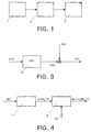
- FIG. 1 shows a simplified block diagram of a digital transmission system according to the invention, which consists of a transmitter 1, a transmission channel 2 and a receiver 3.
- FIG. 2 shows in more detail a block diagram of a baseband model of the transmission system.
- a microphone with an A / D converter in transmitter 1 of the mobile radio device generates a sequence of binary symbols d [i] ⁇ ⁇ 0; 1 ⁇ , which are modulated with QPSK modulation (Quarternary Phase-Shift Keying).
- QPSK modulation Quadratternary Phase-Shift Keying
- the transmission signal formed by means of a transmission pulse shaper with an impulse response h s (t) from the symbols b [k] is transmitted via a possibly time-variant transmission channel 2.
- the channel impulse response h c (t) also takes into account the intersymbol interference (ISI).
- ISI intersymbol interference
- the received signal r (t) is filtered, sampled in a symbol clock T, then normalized and possibly derotated, so that a sequence of received symbols r [k] is created.
- the resulting total impulse response for the transmission from the transmission filter h s (t), channel h c (t) and reception filter is denoted by h (t) or h [k] in the symbol clock model. You can in the usual way, for. B.
- the sequence r [k] is fed to a receiver 7, which uses the estimated total brain pulse response h [k] to form estimated values a ⁇ [kk max ] for the transmitted symbols a [k], k max describing a delay in the symbols.
- FIG. 3 shows the symbol clock model for the transmission system in which the signals occurring in the transmission system are described as a symbol at the time k of the clock become.
- the symbols a [k] are sent over an overall transmission channel 12 transmitted with the total impulse response h [k], so that noisy, received Symbols y [k] arise.
- These symbols y [k] each have a noise component n [k] superimposed, assuming that the symbols n [k] are uncorrelated and according to a Gaussian curve are distributed.
- the superimposed symbols y [k] and n [k] form the received symbols Symbols r [k].
- i 0, .., M-1; ⁇ ⁇ ⁇ 0, ⁇ / M ⁇ .
- the differential precoding according to Eq. (2) only enables the use of an incoherent receiver.
- the noise sequence n [k] is assumed to be white and Gaussian.
- the receive filter in the receiver input stage has a so-called root Nyquist characteristic, from which the uncorrelatedness of successive interference samples n [k] follows. If the reception filter has a different characteristic, a whitening filter must also be provided.
- ⁇ denotes any, but constant phase, which is only approximately fulfilled for channels with carrier frequency offset. Nevertheless, the incoherent receiver is very robust with respect to frequency offset, since in contrast to coherent receivers, the phase rotations caused by the frequency offset do not add up over all symbols.
- An optimal incoherent reception procedure in terms of the maximum likelihood criterion (ML-) cannot be easily implemented in its original form.
- a modification of the optimal method leads to a multi-symbol maximum likelihood sequence estimation (MSMLSE) method, that with the help of known Viterbi algorithm can be implemented inexpensively.
- MSMLSE multi-symbol maximum likelihood sequence estimation
- Each possible transmission sequence has a corresponding noiseless reception sequence ⁇ y ⁇ [ k ] ⁇ N + L -1 / 0.
- the extension of the reception sequence from N to N + L-1 results because the channel has a memory depth of L-1 symbols.
- y ⁇ , ⁇ ) with respect to the complex reception mirror r assuming a received useful signal vector y Specify ⁇ and the assumed carrier phase difference ⁇ : f r
- y ⁇ , ⁇ ) 1 ( ⁇ 2nd n ) N + L exp - ⁇ r - e j ⁇ ⁇ y ⁇ ⁇ 2nd ⁇ 2nd n .
- the metric according to Eq. (10) has no recursive structure, it is an efficient one Initially, it was not possible to implement the metric using the Viterbi algorithm. Around The metric can be modified to enable a cost-effective implementation become. A suitable modification is the MSMLSE method described below represents.
- Eq. (11) shows that the individual blocks always overlap by a receive symbol r [k]. This overlap is necessary so that the reference phase is retained. It should be noted that the MSMLSE method can overlap more than one symbol. However, this increases the implementation effort considerably. With the help of Eq. (10) and Eq.
- 2nd -2 k ( v -1)( N B -1) v ( N B -1) r [ k ] ⁇ y * ⁇ [ k ] .
- a block corresponds to a branch in the trellis diagram belonging to the Viterbi algorithm.
- the Viterbi algorithm requires M L-1 states in the MSMLSE method. Also occur per time step Transitions on. This means an increase by a factor compared to a coherent MLSE method von For N B > 2 more transitions are necessary than with the coherent method.
- FIG. 4 The basic structure of the MSMLSE receiver according to the invention is shown in FIG. 4.
- These symbol blocks are then processed in the equalizer 9 using the MSMLSE method described above.
Landscapes
- Engineering & Computer Science (AREA)
- Computer Networks & Wireless Communication (AREA)
- Signal Processing (AREA)
- Power Engineering (AREA)
- Cable Transmission Systems, Equalization Of Radio And Reduction Of Echo (AREA)
- Digital Transmission Methods That Use Modulated Carrier Waves (AREA)
- Dc Digital Transmission (AREA)
- Mobile Radio Communication Systems (AREA)
Applications Claiming Priority (2)
| Application Number | Priority Date | Filing Date | Title |
|---|---|---|---|
| DE19824408A DE19824408A1 (de) | 1998-05-30 | 1998-05-30 | Empfänger für ein digitales Übertragungssystem |
| DE19824408 | 1998-05-30 |
Publications (4)
| Publication Number | Publication Date |
|---|---|
| EP0963084A2 true EP0963084A2 (fr) | 1999-12-08 |
| EP0963084A3 EP0963084A3 (fr) | 2001-11-07 |
| EP0963084B1 EP0963084B1 (fr) | 2012-02-29 |
| EP0963084B8 EP0963084B8 (fr) | 2012-04-04 |
Family
ID=7869527
Family Applications (1)
| Application Number | Title | Priority Date | Filing Date |
|---|---|---|---|
| EP99201611A Expired - Lifetime EP0963084B8 (fr) | 1998-05-30 | 1999-05-21 | Récepteur pour système de transmission numérique |
Country Status (7)
| Country | Link |
|---|---|
| US (1) | US6345076B1 (fr) |
| EP (1) | EP0963084B8 (fr) |
| JP (1) | JP2000068906A (fr) |
| KR (1) | KR100626103B1 (fr) |
| CN (1) | CN1153424C (fr) |
| DE (1) | DE19824408A1 (fr) |
| TW (1) | TW432843B (fr) |
Cited By (1)
| Publication number | Priority date | Publication date | Assignee | Title |
|---|---|---|---|---|
| DE102007040273B4 (de) * | 2007-08-24 | 2015-02-12 | Sebastian Hoffmann | Verfahren und Vorrichtung zur Schätzung einer Bezugsphase für die Demodulation von phasenmodulierten Signalen |
Families Citing this family (13)
| Publication number | Priority date | Publication date | Assignee | Title |
|---|---|---|---|---|
| US6674815B2 (en) * | 1999-06-16 | 2004-01-06 | Ericsson, Inc | Method for symbol-spaced estimation and/or tracking of a fractionally-spaced fading radio channel |
| US6512802B1 (en) * | 1999-09-28 | 2003-01-28 | Nortel Networks Limited | Method and apparatus for equalization and data symbol detection for MPSK modulation |
| SE521276C2 (sv) * | 1999-11-18 | 2003-10-14 | Ericsson Telefon Ab L M | Transmissionssystem av flerbärvågstyp |
| US6639537B1 (en) * | 2000-03-31 | 2003-10-28 | Massachusetts Institute Of Technology | Highly linear analog-to-digital conversion system and method thereof |
| DE10044227A1 (de) * | 2000-09-07 | 2002-04-04 | Nanotron Ges Fuer Mikrotechnik | Verfahren zum Codieren und Decodieren eines Informationssymbols |
| DE10326810A1 (de) * | 2003-06-13 | 2005-01-13 | Siemens Ag | Verfahren zur Schätzung von in einem Funkblock über einen Funkkanal gesendeten Dateneinheiten sowie empfangende Station |
| KR100556401B1 (ko) | 2003-12-04 | 2006-03-03 | 엘지전자 주식회사 | Vsb 수신 시스템의 등화 장치 |
| US7308049B2 (en) * | 2004-02-05 | 2007-12-11 | Pctel, Inc. | Method and apparatus for noncoherent signal processing in pilotless wireless systems |
| US7286313B2 (en) * | 2004-05-26 | 2007-10-23 | Seagate Technology, Llc | Correcting radial incoherence in servo track sensing |
| US7403746B2 (en) * | 2005-01-04 | 2008-07-22 | Mitsubishi Electric Research Laboratories, Inc. | Adaptive frame durations for time-hopped impulse radio systems |
| US7724844B2 (en) * | 2007-01-31 | 2010-05-25 | Seagate Technology Llc | Detection of servo data for a servo system |
| US8625722B2 (en) | 2010-07-30 | 2014-01-07 | Sensus Usa Inc. | GFSK receiver architecture and methodology |
| FR3038800A1 (fr) * | 2015-07-09 | 2017-01-13 | Stmicroelectronics Rousset | Procede de traitement d'un signal issu d'un canal de transmission, en particulier un signal vehicule par courant porteur en ligne, et notamment l'estimation du canal, et recepteur correspondant |
Family Cites Families (7)
| Publication number | Priority date | Publication date | Assignee | Title |
|---|---|---|---|---|
| FR2546011B1 (fr) * | 1983-05-09 | 1986-02-21 | Vallet Robert | Procede de demodulation non-coherente d'un signal module lineairement a energie par symbole constante et demodulateur pour la mise en oeuvre dudit procede |
| US5818876A (en) * | 1993-02-01 | 1998-10-06 | Motorola, Inc. | Method and apparatus of adaptive maximum likelihood sequence estimation using a variable convergence step size |
| JPH08307283A (ja) * | 1995-03-09 | 1996-11-22 | Oki Electric Ind Co Ltd | 最尤系列推定器及び最尤系列推定方法 |
| DE19614543C1 (de) * | 1996-04-12 | 1997-08-28 | Philips Patentverwaltung | Entzerrer mit erweiterter Kanalschätzung für einen Empfänger in einem digitalen Übertragungssystem |
| US5905743A (en) * | 1996-12-31 | 1999-05-18 | Ericsson Inc. | Apparatus, methods and computer program products for sequential maximum likelihood estimating communications signals using whitening path metrics |
| US6034997A (en) * | 1997-08-19 | 2000-03-07 | Stanford Telecommunications, Inc. | Trellis decoding with multiple symbol noncoherent detection and interleaving to combat frequency offset |
| US5887035A (en) * | 1997-10-31 | 1999-03-23 | Ericsson, Inc. | Method for joint equalization and detection of multiple user signals |
-
1998
- 1998-05-30 DE DE19824408A patent/DE19824408A1/de not_active Withdrawn
-
1999
- 1999-01-28 TW TW088101303A patent/TW432843B/zh not_active IP Right Cessation
- 1999-04-26 US US09/299,528 patent/US6345076B1/en not_active Expired - Lifetime
- 1999-05-21 EP EP99201611A patent/EP0963084B8/fr not_active Expired - Lifetime
- 1999-05-27 CN CNB99106920XA patent/CN1153424C/zh not_active Expired - Fee Related
- 1999-05-29 KR KR1019990019628A patent/KR100626103B1/ko not_active IP Right Cessation
- 1999-05-31 JP JP11152752A patent/JP2000068906A/ja active Pending
Non-Patent Citations (5)
| Title |
|---|
| ADACHI F: "MLSE differential phase detection for M-ary DPSK" IEE PROCEEDINGS: COMMUNICATIONS, INSTITUTION OF ELECTRICAL ENGINEERS, GB, Bd. 141, Nr. 6, 1. Dezember 1994 (1994-12-01), Seiten 407-12, XP006001685 ISSN: 1350-2425 * |
| ADACHI F: "Reduced state transition Viterbi differential detection of M-ary DPSK signals" ELECTRONICS LETTERS, IEE STEVENAGE, GB, Bd. 32, Nr. 12, 6. Juni 1996 (1996-06-06), Seiten 1064-1066, XP006005218 ISSN: 0013-5194 * |
| COLAVOLPE G ET AL: "NON-COHERENT SEQUENCE DETECTION OF M-ARY PSK" 1997 IEEE INTERNATIONAL CONFERENCE ON COMMUNICATIONS. MONTREAL, JUNE 8 - 12, 1997, IEEE INTERNATIONAL CONFERENCE ON COMMUNICATIONS (ICC), NEW YORK, NY: IEEE, US, Bd. 1, 8. Juni 1997 (1997-06-08), Seiten 21-25, XP000740196 ISBN: 0-7803-3926-6 * |
| FREEBERSYSER J A ET AL: "NON-REDUNDANT ERROR CORRECTION OF UNCODED M-DPSK USING A MODIFIED VITERBI ALGORITHM AND A SLIDING BLOCK NON-COHERENT MULTI-SYMBOL DETECTOR" SERVING HUMANITY THROUGH COMMUNICATIONS. SUPERCOMM/ICC. NEW ORLEANS, MAY 1 - 5, 1994, INTERNATIONAL CONFERENCE ON COMMUNICATIONS (ICC), NEW YORK, IEEE, US, Bd. 2, 1. Mai 1994 (1994-05-01), Seiten 950-955, XP000438646 * |
| KIASALEH K ET AL: "MULTIPLE-SYMBOL DIFFERENTIAL DETECTION OF DQPSK AND DPSK MOBILE COMMUNICATION SYSTEMS IMPAIRED BY OSCILLATOR PHASE NOISE" IEEE GLOBAL TELECOMMUNICATIONS CONFERENCE. PHOENIX, ARIZONA, NOV. 3 - 8, 1997, GLOBAL TELECOMMUNICATIONS CONFERENCE (GLOBECOM), NEW YORK, IEEE, US, Bd. 3, 3. November 1997 (1997-11-03), Seiten 1215-1219, XP000737723 ISBN: 0-7803-4199-6 * |
Cited By (1)
| Publication number | Priority date | Publication date | Assignee | Title |
|---|---|---|---|---|
| DE102007040273B4 (de) * | 2007-08-24 | 2015-02-12 | Sebastian Hoffmann | Verfahren und Vorrichtung zur Schätzung einer Bezugsphase für die Demodulation von phasenmodulierten Signalen |
Also Published As
| Publication number | Publication date |
|---|---|
| EP0963084B8 (fr) | 2012-04-04 |
| JP2000068906A (ja) | 2000-03-03 |
| CN1153424C (zh) | 2004-06-09 |
| TW432843B (en) | 2001-05-01 |
| US6345076B1 (en) | 2002-02-05 |
| KR100626103B1 (ko) | 2006-09-20 |
| EP0963084B1 (fr) | 2012-02-29 |
| CN1237845A (zh) | 1999-12-08 |
| DE19824408A1 (de) | 1999-12-02 |
| EP0963084A3 (fr) | 2001-11-07 |
| KR19990088679A (ko) | 1999-12-27 |
Similar Documents
| Publication | Publication Date | Title |
|---|---|---|
| DE69230722T2 (de) | Verfahren zur Dekodierung eines zeitvariablen Kanals | |
| DE69131167T2 (de) | Vorrichtung und verfahren zum entzerren eines verzerrten signals in einem empfänger | |
| DE69029330T2 (de) | Weich entscheidendes dekodieren mit kanalentzerrung | |
| DE69729709T2 (de) | Entzerrer mit einem folgeschätzungsverfahren mit zustandsverkleinerung für einen empfänger in einem digitalen übertragungssystem | |
| DE69734561T2 (de) | Entzerrer mit erweiterter kanalschätzung für einen empfänger in einem digitalen übertragungssystem | |
| DE69837057T2 (de) | Nichtkohärente Folgeschätzungsempfänger für digitalen Modulationen | |
| EP1221780B1 (fr) | Méthode et système pour la suppression d'interférence d'une transmission TDMA et/ou FDMA | |
| EP0963084A2 (fr) | Récepteur pour système de transmission numérique | |
| EP0349603B1 (fr) | Procede et agencement d'egalisation de canaux dispersifs lineaires ou presque lineaires de transmission de signaux | |
| DE69932118T2 (de) | Kanalschätzung unter Verwendung von Weichentscheidungsrückkoppelung | |
| DE69310775T2 (de) | Systeme mit erhöhter geschwindigkeit der informationsübertragung, welche eingebettete abtastmodulation und vorverzerrungsausgleich verwenden | |
| DE69217518T2 (de) | Iteratives Verfahren zur Verminderung von Nachbarsymbolstörungen, sowie entsprechende Empfangsvorrichtung und Anwendung | |
| EP1293073B1 (fr) | Demodulateur pour signaux a modulation par deplacement de frequence a continuite de phase (cpfsk) faisant appel a une approximation lineaire du signal cpfsk | |
| EP0545159B1 (fr) | Procédé de transmission radio numérique avec estimation de la résponse impulsionnelle du canal | |
| EP0664625A2 (fr) | Méthode d'estimation de la qualité d'une liaison de transmission | |
| DE69824898T2 (de) | Schätzung der kanalimpulsantwort mittels der streuung vom empfangenen signal | |
| EP1179936B1 (fr) | Démodulateur pour signaux FSK à phase continue (CPFSK) utilisant une approximation linéaire du signal CPFSK | |
| EP1210787B1 (fr) | Procede permettant d'evaluer le taux d'erreurs sur les bits dans un recepteur radio et recepteur radio correspondant | |
| DE102018202648B4 (de) | Empfänger und Verfahren zum Empfangen eines Kombinationssignals unter Verwendung von Wahrscheinlichkeitsdichtefunktionen | |
| EP1316182B1 (fr) | Egalisation de canal amelioree pour recepteur de telephonie mobile | |
| EP0921664B1 (fr) | Procédé de transmission d'information numérique | |
| DE60032906T2 (de) | Verfahren und Vorrichtung zur Kanalschätzung, insbesondere für ein Mobiltelefon | |
| EP0843444A2 (fr) | Système de communication numérique, utilisant un procédé d'estimation à base de treillis à nombre d'états reduit | |
| EP1516470A1 (fr) | Procede d'egalisation et de demodulation d'un signal de donnees transmis par l'intermediaire d'un canal variable dans le temps | |
| DE10111496A1 (de) | Verfahren zum Entzerren von Signalen und Vorrichtung zur Durchführung des Verfahrens |
Legal Events
| Date | Code | Title | Description |
|---|---|---|---|
| PUAI | Public reference made under article 153(3) epc to a published international application that has entered the european phase |
Free format text: ORIGINAL CODE: 0009012 |
|
| AK | Designated contracting states |
Kind code of ref document: A2 Designated state(s): AT BE CH CY DE DK ES FI FR GB GR IE IT LI LU MC NL PT SE Kind code of ref document: A2 Designated state(s): DE FR GB |
|
| AX | Request for extension of the european patent |
Free format text: AL;LT;LV;MK;RO;SI |
|
| RAP3 | Party data changed (applicant data changed or rights of an application transferred) |
Owner name: KONINKLIJKE PHILIPS ELECTRONICS N.V. Owner name: PHILIPS CORPORATE INTELLECTUAL PROPERTY GMBH |
|
| PUAL | Search report despatched |
Free format text: ORIGINAL CODE: 0009013 |
|
| AK | Designated contracting states |
Kind code of ref document: A3 Designated state(s): AT BE CH CY DE DK ES FI FR GB GR IE IT LI LU MC NL PT SE |
|
| AX | Request for extension of the european patent |
Free format text: AL;LT;LV;MK;RO;SI |
|
| RIC1 | Information provided on ipc code assigned before grant |
Free format text: 7H 04L 25/03 A, 7H 04L 27/22 B, 7H 04L 27/233 B |
|
| 17P | Request for examination filed |
Effective date: 20020507 |
|
| AKX | Designation fees paid |
Free format text: DE FR GB |
|
| RAP1 | Party data changed (applicant data changed or rights of an application transferred) |
Owner name: KONINKLIJKE PHILIPS ELECTRONICS N.V. Owner name: PHILIPS CORPORATE INTELLECTUAL PROPERTY GMBH |
|
| RAP1 | Party data changed (applicant data changed or rights of an application transferred) |
Owner name: KONINKLIJKE PHILIPS ELECTRONICS N.V. Owner name: PHILIPS INTELLECTUAL PROPERTY & STANDARDS GMBH |
|
| 17Q | First examination report despatched |
Effective date: 20050118 |
|
| APBN | Date of receipt of notice of appeal recorded |
Free format text: ORIGINAL CODE: EPIDOSNNOA2E |
|
| APBR | Date of receipt of statement of grounds of appeal recorded |
Free format text: ORIGINAL CODE: EPIDOSNNOA3E |
|
| APBV | Interlocutory revision of appeal recorded |
Free format text: ORIGINAL CODE: EPIDOSNIRAPE |
|
| 17Q | First examination report despatched |
Effective date: 20050118 |
|
| RAP1 | Party data changed (applicant data changed or rights of an application transferred) |
Owner name: NXP B.V. |
|
| GRAP | Despatch of communication of intention to grant a patent |
Free format text: ORIGINAL CODE: EPIDOSNIGR1 |
|
| GRAS | Grant fee paid |
Free format text: ORIGINAL CODE: EPIDOSNIGR3 |
|
| GRAA | (expected) grant |
Free format text: ORIGINAL CODE: 0009210 |
|
| AK | Designated contracting states |
Kind code of ref document: B1 Designated state(s): DE FR GB |
|
| REG | Reference to a national code |
Ref country code: GB Ref legal event code: FG4D Free format text: NOT ENGLISH |
|
| REG | Reference to a national code |
Ref country code: DE Ref legal event code: R081 Ref document number: 59915324 Country of ref document: DE Owner name: OCT CIRCUIT TECHNOLOGIES INTERNATIONAL LTD., IE Free format text: FORMER OWNER: PHILIPS CORPORATE INTELLECTUAL PROPERTY GMBH, 20099 HAMBURG, DE |
|
| RAP2 | Party data changed (patent owner data changed or rights of a patent transferred) |
Owner name: ST-ERICSSON SA |
|
| REG | Reference to a national code |
Ref country code: DE Ref legal event code: R096 Ref document number: 59915324 Country of ref document: DE Effective date: 20120426 |
|
| REG | Reference to a national code |
Ref country code: DE Ref legal event code: R081 Ref document number: 59915324 Country of ref document: DE Owner name: OCT CIRCUIT TECHNOLOGIES INTERNATIONAL LTD., IE Free format text: FORMER OWNER: NXP B.V., EINDHOVEN, NL |
|
| PLBE | No opposition filed within time limit |
Free format text: ORIGINAL CODE: 0009261 |
|
| STAA | Information on the status of an ep patent application or granted ep patent |
Free format text: STATUS: NO OPPOSITION FILED WITHIN TIME LIMIT |
|
| 26N | No opposition filed |
Effective date: 20121130 |
|
| REG | Reference to a national code |
Ref country code: DE Ref legal event code: R097 Ref document number: 59915324 Country of ref document: DE Effective date: 20121130 |
|
| REG | Reference to a national code |
Ref country code: FR Ref legal event code: PLFP Year of fee payment: 18 |
|
| REG | Reference to a national code |
Ref country code: DE Ref legal event code: R082 Ref document number: 59915324 Country of ref document: DE Representative=s name: GRUENECKER PATENT- UND RECHTSANWAELTE PARTG MB, DE Ref country code: DE Ref legal event code: R081 Ref document number: 59915324 Country of ref document: DE Owner name: OCT CIRCUIT TECHNOLOGIES INTERNATIONAL LTD., IE Free format text: FORMER OWNER: ST-ERICSSON SA, PLAN-LES-OUATES, CH |
|
| REG | Reference to a national code |
Ref country code: FR Ref legal event code: PLFP Year of fee payment: 19 |
|
| PGFP | Annual fee paid to national office [announced via postgrant information from national office to epo] |
Ref country code: DE Payment date: 20170420 Year of fee payment: 19 Ref country code: FR Payment date: 20170421 Year of fee payment: 19 Ref country code: GB Payment date: 20170426 Year of fee payment: 19 |
|
| REG | Reference to a national code |
Ref country code: FR Ref legal event code: TP Owner name: OCT CIRCUIT TECHNOLOGIES INTERNATIONAL LIMITED, IE Effective date: 20180116 |
|
| REG | Reference to a national code |
Ref country code: DE Ref legal event code: R119 Ref document number: 59915324 Country of ref document: DE |
|
| GBPC | Gb: european patent ceased through non-payment of renewal fee |
Effective date: 20180521 |
|
| PG25 | Lapsed in a contracting state [announced via postgrant information from national office to epo] |
Ref country code: DE Free format text: LAPSE BECAUSE OF NON-PAYMENT OF DUE FEES Effective date: 20181201 Ref country code: GB Free format text: LAPSE BECAUSE OF NON-PAYMENT OF DUE FEES Effective date: 20180521 Ref country code: FR Free format text: LAPSE BECAUSE OF NON-PAYMENT OF DUE FEES Effective date: 20180531 |