EP0962995A2 - Lithium secondary battery - Google Patents
Lithium secondary battery Download PDFInfo
- Publication number
- EP0962995A2 EP0962995A2 EP99110555A EP99110555A EP0962995A2 EP 0962995 A2 EP0962995 A2 EP 0962995A2 EP 99110555 A EP99110555 A EP 99110555A EP 99110555 A EP99110555 A EP 99110555A EP 0962995 A2 EP0962995 A2 EP 0962995A2
- Authority
- EP
- European Patent Office
- Prior art keywords
- tabs
- lithium secondary
- secondary battery
- less
- current
- Prior art date
- Legal status (The legal status is an assumption and is not a legal conclusion. Google has not performed a legal analysis and makes no representation as to the accuracy of the status listed.)
- Granted
Links
Images


Classifications
-
- B—PERFORMING OPERATIONS; TRANSPORTING
- B60—VEHICLES IN GENERAL
- B60K—ARRANGEMENT OR MOUNTING OF PROPULSION UNITS OR OF TRANSMISSIONS IN VEHICLES; ARRANGEMENT OR MOUNTING OF PLURAL DIVERSE PRIME-MOVERS IN VEHICLES; AUXILIARY DRIVES FOR VEHICLES; INSTRUMENTATION OR DASHBOARDS FOR VEHICLES; ARRANGEMENTS IN CONNECTION WITH COOLING, AIR INTAKE, GAS EXHAUST OR FUEL SUPPLY OF PROPULSION UNITS IN VEHICLES
- B60K6/00—Arrangement or mounting of plural diverse prime-movers for mutual or common propulsion, e.g. hybrid propulsion systems comprising electric motors and internal combustion engines
- B60K6/20—Arrangement or mounting of plural diverse prime-movers for mutual or common propulsion, e.g. hybrid propulsion systems comprising electric motors and internal combustion engines the prime-movers consisting of electric motors and internal combustion engines, e.g. HEVs
- B60K6/22—Arrangement or mounting of plural diverse prime-movers for mutual or common propulsion, e.g. hybrid propulsion systems comprising electric motors and internal combustion engines the prime-movers consisting of electric motors and internal combustion engines, e.g. HEVs characterised by apparatus, components or means specially adapted for HEVs
- B60K6/28—Arrangement or mounting of plural diverse prime-movers for mutual or common propulsion, e.g. hybrid propulsion systems comprising electric motors and internal combustion engines the prime-movers consisting of electric motors and internal combustion engines, e.g. HEVs characterised by apparatus, components or means specially adapted for HEVs characterised by the electric energy storing means, e.g. batteries or capacitors
-
- H—ELECTRICITY
- H01—ELECTRIC ELEMENTS
- H01M—PROCESSES OR MEANS, e.g. BATTERIES, FOR THE DIRECT CONVERSION OF CHEMICAL ENERGY INTO ELECTRICAL ENERGY
- H01M10/00—Secondary cells; Manufacture thereof
- H01M10/04—Construction or manufacture in general
- H01M10/0431—Cells with wound or folded electrodes
-
- H—ELECTRICITY
- H01—ELECTRIC ELEMENTS
- H01M—PROCESSES OR MEANS, e.g. BATTERIES, FOR THE DIRECT CONVERSION OF CHEMICAL ENERGY INTO ELECTRICAL ENERGY
- H01M50/00—Constructional details or processes of manufacture of the non-active parts of electrochemical cells other than fuel cells, e.g. hybrid cells
- H01M50/50—Current conducting connections for cells or batteries
- H01M50/531—Electrode connections inside a battery casing
- H01M50/534—Electrode connections inside a battery casing characterised by the material of the leads or tabs
-
- H—ELECTRICITY
- H01—ELECTRIC ELEMENTS
- H01M—PROCESSES OR MEANS, e.g. BATTERIES, FOR THE DIRECT CONVERSION OF CHEMICAL ENERGY INTO ELECTRICAL ENERGY
- H01M50/00—Constructional details or processes of manufacture of the non-active parts of electrochemical cells other than fuel cells, e.g. hybrid cells
- H01M50/50—Current conducting connections for cells or batteries
- H01M50/531—Electrode connections inside a battery casing
- H01M50/536—Electrode connections inside a battery casing characterised by the method of fixing the leads to the electrodes, e.g. by welding
-
- H—ELECTRICITY
- H01—ELECTRIC ELEMENTS
- H01M—PROCESSES OR MEANS, e.g. BATTERIES, FOR THE DIRECT CONVERSION OF CHEMICAL ENERGY INTO ELECTRICAL ENERGY
- H01M50/00—Constructional details or processes of manufacture of the non-active parts of electrochemical cells other than fuel cells, e.g. hybrid cells
- H01M50/50—Current conducting connections for cells or batteries
- H01M50/531—Electrode connections inside a battery casing
- H01M50/538—Connection of several leads or tabs of wound or folded electrode stacks
-
- H—ELECTRICITY
- H01—ELECTRIC ELEMENTS
- H01M—PROCESSES OR MEANS, e.g. BATTERIES, FOR THE DIRECT CONVERSION OF CHEMICAL ENERGY INTO ELECTRICAL ENERGY
- H01M10/00—Secondary cells; Manufacture thereof
- H01M10/05—Accumulators with non-aqueous electrolyte
- H01M10/052—Li-accumulators
- H01M10/0525—Rocking-chair batteries, i.e. batteries with lithium insertion or intercalation in both electrodes; Lithium-ion batteries
-
- Y—GENERAL TAGGING OF NEW TECHNOLOGICAL DEVELOPMENTS; GENERAL TAGGING OF CROSS-SECTIONAL TECHNOLOGIES SPANNING OVER SEVERAL SECTIONS OF THE IPC; TECHNICAL SUBJECTS COVERED BY FORMER USPC CROSS-REFERENCE ART COLLECTIONS [XRACs] AND DIGESTS
- Y02—TECHNOLOGIES OR APPLICATIONS FOR MITIGATION OR ADAPTATION AGAINST CLIMATE CHANGE
- Y02E—REDUCTION OF GREENHOUSE GAS [GHG] EMISSIONS, RELATED TO ENERGY GENERATION, TRANSMISSION OR DISTRIBUTION
- Y02E60/00—Enabling technologies; Technologies with a potential or indirect contribution to GHG emissions mitigation
- Y02E60/10—Energy storage using batteries
-
- Y—GENERAL TAGGING OF NEW TECHNOLOGICAL DEVELOPMENTS; GENERAL TAGGING OF CROSS-SECTIONAL TECHNOLOGIES SPANNING OVER SEVERAL SECTIONS OF THE IPC; TECHNICAL SUBJECTS COVERED BY FORMER USPC CROSS-REFERENCE ART COLLECTIONS [XRACs] AND DIGESTS
- Y02—TECHNOLOGIES OR APPLICATIONS FOR MITIGATION OR ADAPTATION AGAINST CLIMATE CHANGE
- Y02P—CLIMATE CHANGE MITIGATION TECHNOLOGIES IN THE PRODUCTION OR PROCESSING OF GOODS
- Y02P70/00—Climate change mitigation technologies in the production process for final industrial or consumer products
- Y02P70/50—Manufacturing or production processes characterised by the final manufactured product
-
- Y—GENERAL TAGGING OF NEW TECHNOLOGICAL DEVELOPMENTS; GENERAL TAGGING OF CROSS-SECTIONAL TECHNOLOGIES SPANNING OVER SEVERAL SECTIONS OF THE IPC; TECHNICAL SUBJECTS COVERED BY FORMER USPC CROSS-REFERENCE ART COLLECTIONS [XRACs] AND DIGESTS
- Y10—TECHNICAL SUBJECTS COVERED BY FORMER USPC
- Y10S—TECHNICAL SUBJECTS COVERED BY FORMER USPC CROSS-REFERENCE ART COLLECTIONS [XRACs] AND DIGESTS
- Y10S903/00—Hybrid electric vehicles, HEVS
- Y10S903/902—Prime movers comprising electrical and internal combustion motors
- Y10S903/903—Prime movers comprising electrical and internal combustion motors having energy storing means, e.g. battery, capacitor
- Y10S903/904—Component specially adapted for hev
- Y10S903/907—Electricity storage, e.g. battery, capacitor
Definitions
- the present invention relates to a lithium secondary battery which maintains a good charge-discharge cycle and in which safety may be secured with electricity being cut off when an excess current has occurred due to external short circuit, etc. so that the battery may not be exploded nor be ignited, and in particular, to a lithium secondary battery which may be preferably used for driving a motor of an electric vehicle, etc.
- the internal electrode body of a lithium secondary battery comprises a positive electrode, a negative electrode and a separator made of porous polymer film, the positive electrode and the negative electrode being wound or laminated via the separator so that the positive electrode and negative electrode are not brought into direct contact with each other.
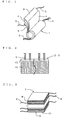
- an internal electrode body 1 of winding type is formed by winding a positive electrode 2 and a negative electrode 3, having a separator 4 in between, and tabs 5 are provided for each of positive and negative electrodes 2, 3 (hereafter referred to "electrodes 2, 3") respectively.
- each tab 5 is attached to an external terminal (not shown) or an electric current extracting terminal (not shown) being conductive to the external terminal. That is, the tab 5 serves to act as a lead line (a current path) being conductive to the external terminal, etc. together with conducting current collecting from electrodes 2, 3.
- a plan view of the electrodes 2, 3 when the internal electrode body 1 is spread out is shown in Fig. 2.
- the electrodes 2, 3 are formed with an electrode active material being coated respectively onto metal foils 15 made of aluminum, etc. for positive electrode 2 and made of copper for negative electrode 3 respectively as current collecting bodies, thus forming an electrode active material layer 16.
- the tab 5 is provided on one side of such a metal foil 15, and those having thin band shape are preferably used so that the portion where the tab 5 of the electrodes 2, 3 are attached may not swell to the direction of a periphery when the internal electrode body 1 was formed. In addition, they are preferably disposed in approximately uniform distance so that one tab 5 conducts current collecting from a constant area in the electrodes 2, 3.
- a material to be used for the tab 5 is the same as a material of the metal foil 15 to which the tab 5 is attached.
- lithium secondary batteries with a voltage of around 4 V at the highest for a single battery, such single batteries in plurality being connected in series, since a constant voltage is required to drive a motor, and, however, there is a case where discharge of a large current not less than 100 A is required to obtain the herein desired acceleration performance or gradeability. For example, maintaining that 200 V with 100 A be required and 3.6 V be an average terminal voltage at the time of discharge thereof, 56 units of single batteries are required to be connected in series, resulting in 100 A current flowing at each single battery at this time.
- the internal configuration of a battery must be designed so that also in the case where such a huge current flows, the battery may normally operate while the output loss is suppressed as low as possible. Therefore, paying attention to the current path from the above described internal electrode body 1 and the external terminal, it is deemed preferable that the resistance of members themselves of the electrodes 2, 3 as well as the metal foils 15, or the tabs 5 and the external terminals, etc. all configuring the electrodes 2, 3 is small.
- the tab 5 has an allowable range to set up a resistance value on a point of view of feasibility to set up its shape freely as far as the shape of the tab 5 is to be housed in the space between the battery case housing the internal electrode body 1 therein and the internal electrode body 1.
- Metal members are used for the tab 5, whose resistance value is generally made smaller, nevertheless, the rate of the resistance value of the tab occupying the total internal resistance of a lithium secondary battery is not necessarily small, and cannot be ignored.
- a tab 5 adopting a larger cross-sectional area to make the resistance value smaller will result in introducing a situation where energy density of a battery gets decreased since the total weight of the tabs 5 will become heavier in spite that effective decrease in the internal resistance and effective decrease in the output loss is expected.
- a current fuse is utilized in various electric appliances, but has never been used up to date as a current cutoff mechanism to be disposed inside a lithium secondary battery since a size or a shape of the current fuse is subject to a limit.
- the tab 5 can function as the current fuse, with which an existing safety device may be replaced or concurrently disposed, it is deemed that a safety increase may be planned.
- the current cutoff value must be determined so that the tab 5 is fused with a predetermined quantity of excess current, but as mentioned above, there is naturally a limit in the structural shape of the tab 5. That is, for the purpose of using the tab 5 as a current fuse, the cross-sectional area of the tab 5 must be set not more than a predetermined value, but at the same time, considering the fact that the quantity of excess current may also defer due to quantity of single battery's internal resistance, it is regarded as necessary to set the cross-sectional area of the tab 5 in accordance with quantity of a single battery's internal resistance.
- the present invention was attained by contemplating the problems of the prior art mentioned above, and its first purpose is to provide a lithium secondary battery having realized reduction in output loss and increase in energy density, and its second purpose is to provide a lithium secondary battery which has been planned to secure and increase in safety by incorporating tabs into the battery as a current fuse, being a replacement for a conventional safety device or to be concurrently disposed, and furthermore its third purpose is to provide a lithium secondary battery which concurrently realizes these characteristics, that is, reduction in output loss and increase in energy density, and security of safety having given tabs a function as a current fuse.
- a lithium secondary battery comprising:
- the relationship between material of the tab and total cross-sectional area of the tabs is preferably not less than 0.009 cm 2 for aluminum, not less than 0.005 cm 2 for copper, and not less than 0.004 cm 2 for nickel, further preferably not less than 0.014 cm 2 for aluminum, not less than 0.008 cm 2 for copper, and not less than 0.008 cm 2 for nickel.
- a thickness of the tab is preferably not more than twice the thickness of an electrode active material layer in an electrode to which the tab is welded, and further preferably not more than thickness of an electrode active material layer, that is, it is preferred that the thickness is set within a range where the portions where the tabs have been attached shall not swell when the tabs are attached to electrodes to be wound or laminated.
- a sum of resistance value of the tabs per a unit battery is preferably not more than 1 m ⁇ .
- a lithium secondary battery comprising:
- the relationship between material of the tabs and their total cross-sectional area of the tubs when internal resistance of a unit battery is set R (m ⁇ ) is preferably not more than 0.36/R (cm 2 ) for aluminum, not more than 0.18/R (cm 2 ) for copper, and not more than 0.14/R (cm 2 ) for nickel, and more preferably not more than 0.18/R (cm 2 ) for aluminum, not more than 0.09/R (cm 2 ) for copper, and not more than 0.07/R (cm 2 ) for nickel.
- the tab is provided with a narrow portion, the tab is easily made to function as a current fuse, which is preferable.
- the internal resistance in the above described lithium secondary battery of the present invention is not more than 10 m ⁇ per a unit battery.
- the relationship between material of the tab and total cross-sectional area of the tabs at not less than 0.008 cm 2 and not more than 0.36/R cm 2 for aluminum, not less than 0.005 cm 2 and not more than 0.18/R cm 2 for copper, and not less than 0.004 cm 2 and not more than 0.14/R cm 2 for nickel, and further preferably at not less than 0.014 cm 2 and not more than 0.18/R cm 2 for aluminum, not less than 0.008 cm 2 and not more than 0.09/R cm 2 for copper, and not less than 0.008 cm 2 and not more than 0.07/R cm 2 for nickel, a battery having the characteristics of the above described two kinds of lithium secondary batteries can be obtained.
- the characteristics of the above described lithium secondary battery of the present invention are preferably adopted as a lithium secondary battery with battery capacity of not less than 5 Ah, and the lithium secondary battery of the present invention is preferably used for an electric vehicle (EV) or for a hybrid electric vehicle (HEV).
- EV electric vehicle
- HEV hybrid electric vehicle
- An internal electrode body of a lithium secondary battery of the present invention (hereinafter referred to as "battery”) comprises a positive electrode, a negative electrode and a separator made of porous polymer film, the positive electrode and the negative electrode being wound or laminated for configuration so that the positive electrode and negative electrode are not brought into direct contact with each other via the separator.
- a wound-type internal electrode body 1 is formed by winding a positive electrode 2 and a negative electrode 3 via a separator 4, and tabs 5 are provided for the electrodes 2, 3.
- these tabs 5 can be attached to the electrodes 2, 3 with means such as supersonic welding, etc. at the time when the electrodes 2, 3 are wound together with the separator 4.
- the lamination-type internal electrode body 7 laminates the positive electrode 8 and the negative electrode 9 alternately via the separator 10 with tabs 6 being connected to each of positive and negative electrodes 8 and 9 (hereinafter referred to "electrodes 8, 9") respectively,
- Such internal electrode body 1, 7 are basically configured to have a plurality of element batteries being connected in parallel, the element battery comprising positive electrodes 2, 8 and negative electrodes 3, 9 facing each other.
- the positive electrodes 2, 8 and the negative electrodes 3, 9 are all produced by forming an electrode active material layer with electrode active materials being coated respectively onto metal foils as the current collecting body.
- aluminum foils are preferably used as the current collecting body for positive electrodes 2, 8 and copper foils as the current collecting body for negative electrodes 3, 9 respectively, but titanium foils may be used as the current collecting body for positive electrodes 2, 8 and nickel foils as the electrode collecting body for negative electrodes 3, 9.
- lithium transition metal compound oxides such as lithium cobalt oxide(LiCoO 2 ), lithium nickel oxide(LiNiO 2 ), lithium manganese oxide (LiMn 2 O 4 ), etc. are generally used as a positive active materials.
- an electrode active material a carbon powder such as acetylene black, graphite powder, etc.
- an amorphous carbon material such as soft carbon or hard carbon, or carbon powder such as artificial graphite and natural graphite, etc. is used.
- the separators 4, 10 it is preferable to use one having a three-layer structure in which a polyethylen film having lithium ion permeability and including micropores is sandwiched between porous polypropylene films having lithium ion permeability,
- This serves also as a safety mechanism in which when the temperature of internal electrode bodies 1, 7 are raised, the polyethylene film is softened at about 130°C so that the micropores are collapsed to suppress the movement of lithium ions, that is, the battery reaction.
- this polyethylene film is sandwiched between the polypropylene films having a softening temperature higher than the said polyethylene film, it becomes possible to prevent the direct contact between the electrodes (2, 3), (8, 9).
- FIG. 4 is a cross-sectional view showing one embodiment of the battery structure.
- the internal electrode body 1 has been inserted in a battery case 11 with the tab 5 of the positive electrode 2 having been connected to a rivet 13 attached on a positive terminal plate 12, and the tab 5 of the negative electrode 3 having been connected to a rivet 13 attached on a negative terminal plate 14 respectively by pressure attachment.
- Electrolyte has been injected inside the battery case 11, and as the electrolyte an carbonic acid ester family such as ethylene carbonate (EC), diethyl carbonate (DEC), and dimethyl carbonate (DMC), and a nonaqueous organic electrolyte in which one or more kinds of lithium fluoride complex compound such as LiPF 6 , and LiBF 4 , etc. or lithium halide such as LiClO 4 as an electrolyte are dissolved in a single solvent or mixed solvent of organic solvents such as propylene carbonate (PC), ⁇ -butyrolactone, tetrahydrofuran, and acetonitrile, etc., are preferably used.
- Such electrolyte can be injected from an open end after the other end of the battery case is sealed, and thereafter, the open end is blockaded, thus the injection can be conducted.
- an insulating sheet 17 has been disposed on the internal wall of the battery case 11 so as to secure insulation for the internal electrode body 1 and the battery case 11. But the function of this insulating sheet 17 may be replaced by the separator 4.
- the tabs 5 must carry out its function as a current path without fusing.
- the total cross-sectional area of the tabs 5 is supposed to have not less than a constant area in accordance with quality of the material to be used for the tab 5 so that at least a plurality of tabs 5 for current collecting to be connected to the electrodes 2, 3 should not respectively fuse also when such a huge current has flown.
- Difference in melting point and resistivity based on the quality of material results in difference in predetermined area based on the quality of material.
- the relationship between material of the tab and total cross-sectional area of the tab is preferably not less than 0.009 cm 2 for aluminum, not less than 0.005 cm 2 for copper, and not less than 0.004 cm 2 for nickel as explained in detail in later described examples. If such cross-sectional area has been secured, an incident that the tab 5 fuses and brings function of the battery to a halt even when a current of 100 A flows can be avoided regardless of the resistance value of the internal electrode body.
- thickness of a tab 5 is not more than twice the thickness of an electrode active material layer 16 in the electrodes 2, 3 to which the tab 5 is welded and further preferably is not more than the thickness of the electrode active material layer 16.
- the thickness of the electrode active material layer 16 refers to the thickness of the electrode active material layer 16 of a unit layer formed on either side of the metal foil 15, that is one-side coating thickness.
- Figs. 5(a) and 5(b) are enlarged cross-sectional views showing one embodiment of the attachment part of the tabs 5 into the electrodes 2, 3 at the positive side in Fig. 4. But, it goes without saying that the similar idea can also be applied to arrangements for the negative side. As shown in Fig. 5(a), if thickness of the tab 5 is not more than twice the thickness of an electrode active material layer 16 in the positive electrode 2 to which the tab 5 is attached, the metal foil 15 as well as the separator 4 are bent in use of the space provided in the end part where any electrode active material layer 16 has not formed, thus the risk that the tabs 5 contacts the positive electrode plate 2 gets smaller.
- the cross-sectional area of the tabs 5 is determined within the range where the tabs do not fuse for the above described predetermined current values, and moreover by considering thickness as well as weight of the tabs 5.
- safety valves using V-shape grooves 19 are only provided in each of positive and negative terminal plates 12, 14 as safety mechanism against excess current such as short circuit current, etc., but, otherwise, it goes without saying that safety mechanisms may be concurrently provided, that is, a PTC element may be provided, or a pressure joint may be provided between the rivet 13 and the external terminal 18.
- a PTC element may be provided, or a pressure joint may be provided between the rivet 13 and the external terminal 18.
- current fuse is disposed in a circuit outside a battery as a mechanism to cut off a current instantly at approximately the same time of occurrence of a huge current.
- At least a plurality of tabs 5 for current collecting to be connected to the electrodes 2, 3 are made to function as current fuses, but in this case, the internal resistance much affects a current value due to which the current fuse works. That is, even if an internal short circuit or an external short circuit takes place, when the internal resistance is huge, a short circuit current does not get larger while much larger excess current flows when the internal resistance is small. Therefore, the fusing current value of a current fuse is preferably set in accordance with the internal resistance.
- this current cutoff value is preferably set in accordance with the material of the tabs 5, and may be determinable by total cross-sectional area of tabs 5.
- the relationship between material of the tabs 5 and total cross-sectional area of the tabs when internal resistance of a unit battery is set R (m ⁇ ) is preferably not more than 0.36/R (cm 2 ) for aluminum, not more than 0.18/R (cm 2 ) for copper, and not more than 0.14/R (cm 2 ) for nickel as explained in detail in the later described examples.
- tabs 5 functional as current fuses even if the external short circuit resistance is around one time the internal resistance
- a current may be cut off without making a safety valve operate, namely without driving out vaporized gas of such as an electrolyte, etc. from inside a battery.
- narrow parts 21 may be preferably provided in the tabs 5, making it easier for the tabs 5 to function as current fuses.
- total cross-sectional area of tabs 5 refers to total cross-sectional area of parts where the cross-sectional area of the narrow parts 21 becomes the smallest.
- the internal resistance is preferably not more than 10 m ⁇ per a unit battery. This is due to a request from a practical point of view that a voltage drop at the time of normal use should be preferably made as small as possible and the output loss should be preferably made as small as possible.
- the relationship between material of the tabs 5 and total cross-sectional area is set at not less than 0.008 cm 2 and not more than 0.36/R cm 2 for aluminum, not less than 0.005 cm 2 and not more than 0.18/R cm 2 for copper, and not less than 0.004 cm 2 and not more than 0.14/R cm 2 for nickel, and further preferably at not less than 0.014 cm 2 and not more than 0.36/R cm 2 for aluminum, not less than 0.008 cm 2 and not more than 0.18/R cm 2 for copper, and not less than 0.008 cm 2 and not more than 0.14/R cm 2 for nickel.
- the characteristics of the above described lithium secondary battery of the present invention are preferably adopted as a lithium secondary battery with battery capacity of not less than 5 Ah, and the lithium secondary battery is preferably used for an electric vehicle (EV) or for a hybrid electric vehicle (HEV).
- EV electric vehicle
- HEV hybrid electric vehicle
- Test sample number Quality of material Thickness ( ⁇ m) Current value (A) Occurrence of fusing of a tab 1 Aluminum 20 25 No 2 20 30 Yes 3 50 50 No 4 50 60 No 5 50 70 Yes 6 Copper 10 25 No 7 10 30 Yes 8 20 40 No 9 20 50 Yes 10 30 50 No 11 30 60 No 12 30 70 Yes
- resistance values of one sheet of tab have been measured, average values of which have been 7m ⁇ for an Al tab (cross-sectional area: 0.002 cm 2 ) with thickness of 20 ⁇ m, 8 m ⁇ for a Cu tab (cross-sectional area: 0.001 cm 2 ) with thickness of 10 ⁇ m, and 8 m ⁇ for an Ni tab (cross-sectional area: 0.001 cm 2 ) with thickness of 10 ⁇ m.
- a battery related to examples and comparative examples which have configuration shown in Fig. 4 have been formed as per the following method.
- a paste has been formed with LiMn 2 O 4 powder body as a positive active material, to which acetylene black has been added to give conductivity to this, and further a binder and a solvent are mixed therewith.
- a positive electrode 2 has been formed having an electrode plane shape of the length towards winding direction 3600 mm ⁇ the width 200 mm.
- a paste has been formed with a highly graphitized carbon powder as a negative active material, with which a binder and a solvent are mixed, and the paste has been coated on the both sides of a copper foil with thickness of 20 ⁇ m, and thereby a negative electrode 3 has been formed having a electrode plane shape of the length towards winding direction 4000 mm ⁇ the width 200 mm.
- the thus-formed positive electrode 2 and negative electrode 3 were wound with insulation by 220 mm-wide separators 4 made of polypropylene and at the same time the number of sheets indicated in Table 2 of each of an Al tab with 10 mm width, 50 mm length, and 20 ⁇ m thickness and a Cu tab with 10 mm width, 50 mm length, and 10 ⁇ m thickness were attached respectively to the electrodes 2, 3 by ultrasonic-welding so that they were arranged to make an approximate straight line along the direction of diameter of the internal electrode body 1, and so that each of electrodes 2, 3 was placed at even distance when they were spread out, and further so that one of the electrodes was formed at one end of the internal electrode body 1.
- the thus-formed internal electrode body 1 was fitted in to the aluminum-made battery case 11, arranging tabs 5 respectively to each positive electrode and negative electrode as shown in Fig. 7 and pressure-attaching the tabs to rivets 13 respectively being the current extracting terminals under pressure of 1 ton/cm 2 , attaching a copper-made negative terminal plate 14 onto the negative rivet 13 and a aluminum-made positive terminal plate 12 onto the positive rivet 13 respectively.
- the negative side of the battery case 11 was sealed, and thereafter, from the open side of positive terminal of the battery case 11, the electrolyte, a mixed solvent of EC and DEC where electrolyte LiPF 6 was dissolved to yield 1 mol% density, was injected into the case and thereafter, the positive side was sealed tightly.
- the tabs 5 have the same total cross-sectional area as that in Example, but there is a difference in method of connection between tabs 5 and an current extracting terminal.
- oxidated film is apt to be formed on their surfaces, and therefore, it is presumed that current concentration took place at a certain tab 5 to fuse as a result of deviation of resistance values of each tab 5 occurring due to differences in the connection state of tabs 5, affected by oxidated film because of lower pressure of pressure attachment in Comparative example 2 as compared with the case of Example, and moreover reduction of current paths due to that fusing resulted in occurrence of fusing of tabs 5 in a chain fashion. Consequently, it is understood that preferably deviation of respective resistance values of tabs 5 ranges within ⁇ 20% of the average value.
- the total cross-sectional area may be made not more than 0.064 cm 2 being 8 times that in the case of current value of 100 A, and similarly, as for Cu tabs not more than 0.040 cm 2 , and as for Ni tabs not more than 0.032 cm 2 so that the tabs fuse at the 800 A current.
- the safety valve did not operate, after short circuit, similar to the case of normal discharge, but in the battery comprising Al tabs having total cross-sectional area of 0.05 cm 2 , the safety valve operated after short circuit. Nevertheless, even in this case, burst or ignition of the battery did not take place in portions other than the safety valve.
- a lithium secondary battery of the present invention As described above, according to a lithium secondary battery of the present invention, an excellent effect that without tab's fusing within a working current range since total cross-sectional area of tabs is set within an appropriate range, reduction in output loss as well as improvement in energy density may further be planned is yielded, and on the other hand, an excellent effect that security of safety as well as improvement in safety may be planned is attained by incorporating tabs as current fuse into a battery. In addition, a remarkable effect that a battery superior in reliability is provided by having these characteristics simultaneously in combined fashion can be achieved.
- a lithium secondary battery includes an internal electrode body including a positive electrode, a negative electrode, and a separator.
- the positive electrode and the negative electrode are wound or laminated via the separator so that the positive electrode and the negative electrode are not brought into direct contact with each other.
- At least a plurality of tabs for current collecting were provided to have a total cross-sectional area of the tabs be not less than a constant area in accordance with the quality of the material to be used for the tabs so that the tabs to be connected to each of the positive and negative electrodes may not respectively fuse when at least 100 A current has flown through the lithium secondary battery.
- the lithium secondary battery maintains a good charge-discharge cycle characteristics, and safety may be secured with electricity being cut off when an excess current has occurred due to external short circuit, etc., so that the battery may not be exploded nor be ignited.
- the lithium secondary battery may be preferably used for driving a motor of an electric vehicle, etc.
Landscapes
- Chemical & Material Sciences (AREA)
- Chemical Kinetics & Catalysis (AREA)
- Electrochemistry (AREA)
- General Chemical & Material Sciences (AREA)
- Engineering & Computer Science (AREA)
- Transportation (AREA)
- Combustion & Propulsion (AREA)
- Mechanical Engineering (AREA)
- Manufacturing & Machinery (AREA)
- Connection Of Batteries Or Terminals (AREA)
- Secondary Cells (AREA)
- Electric Propulsion And Braking For Vehicles (AREA)
- Hybrid Electric Vehicles (AREA)
- Cell Electrode Carriers And Collectors (AREA)
- Battery Electrode And Active Subsutance (AREA)
Abstract
Description
wherein the tabs function as current fuses.
| Test sample number | Quality of material | Thickness (µm) | Current value (A) | Occurrence of fusing of a |
| 1 | | 20 | 25 | |
| 2 | 20 | 30 | | |
| 3 | 50 | 50 | | |
| 4 | 50 | 60 | | |
| 5 | 50 | 70 | | |
| 6 | | 10 | 25 | |
| 7 | 10 | 30 | | |
| 8 | 20 | 40 | | |
| 9 | 20 | 50 | | |
| 10 | 30 | 50 | | |
| 11 | 30 | 60 | | |
| 12 | 30 | 70 | Yes |
| Number of Al tabs | Number of Cu tabs | Method of connection with a current extracting terminal | Result of 100 A current current flow | Result of 200 flow | |
| Example | 10 | 10 | Pressure attachment by rivet | Fusing did not occur | Fusing did not occur |
| Comparative example 1 | 2 | 2 | Pressure attachment by rivet | Fusing occurred | Test not feasible |
| Comparative example 2 | 10 | 10 | Tightening by screw | Fusing did not occur | Fusing occurred |
Claims (13)
- A lithium secondary battery, comprising:an internal electrode body including a positive electrode, a negative electrode, and a separator, the positive electrode and the negative electrode being wound or laminated via the separator so that the positive electrode and the negative electrode are not brought into direct contact with each other;an organic electrolyte; andat least a plurality of tabs to be connected to each of the positive and negative electrodes for current collecting, the tabs having a total cross-sectional area of the tabs be not less than a constant area in accordance with the quality of the material to be used for the tabs so that the tabs to be connected to each of the positive and negative electrodes may not fuse when at least 100 A current flows through the lithium secondary battery.
- The lithium secondary battery according to claim 1, wherein the relationship between material of tabs and total cross-sectional area of the tabs is not less than 0.009 cm2 for aluminum, not less than 0.005 cm2 for copper, and not less than 0.004 cm2 for nickel, and preferably not less than 0.014 cm2 for aluminum, not less than 0.008 cm2 for copper, and not less than 0.008 cm2 for nickel.
- The lithium secondary battery according to claim 1 or 2, wherein a thickness of a tab is not more than twice a thickness of an electrode active material layer in an electrode to which the tabs are welded, and preferably not more than a thickness of the electrode active material layer.
- The lithium secondary battery according to any one of claims 1 through 3, wherein a sum of resistance value of the tabs per a unit battery is not more than 1 mΩ.
- A lithium secondary battery, comprising:an internal electrode body including a positive electrode, a negative electrode, and a separator, the positive electrode and the negative electrode being wound or laminated via a separator so that the positive electrode and the negative electrode are not brought into direct contact with each other;an organic electrolyte; andat least a plurality of tabs to be connected to each of the positive and negative electrodes for current collecting,
wherein the tabs function as current fuses. - The lithium secondary battery according to claim 5, wherein the relationship between material of the tabs and total cross-sectional area of the tabs when internal resistance of a unit battery is set R (mΩ) is not more than 0.36/R (cm2) for aluminum, not more than 0.18/R (cm2) for copper, and not more than 0.14/R (cm2) for nickel, and preferably not more than 0.18/R (cm2) for aluminum, not more than 0.09/R (cm2) for copper, and not more than 0.07/R (cm2) for nickel.
- The lithium secondary battery according to claim 6, wherein the tabs are provided with a narrow portion.
- The lithium secondary battery according to any one of claims 1 through 7, wherein internal resistance is not more than 10 mΩ per a unit battery.
- The lithium secondary battery according to any one of claims 1 through 8, wherein when internal resistance of a unit battery is set R (mΩ), the relationship between material of the tabs and total cross-sectional area of the tabs is not less than 0.008 cm2 and not more than 0.36/R cm2 for aluminum, not less than 0.005 cm2 and not more than 0.18/R cm2 for copper, and not less than 0.004 cm2 and not more than 0.14/R cm2 for nickel, and preferably not less than 0.014 cm2 and not more than 0.18/R cm2 for aluminum, not less than 0.008 cm2 and not more than 0.09/R cm2 for copper, and not less than 0.008 cm2 and not more than 0.07/R cm2 for nickel.
- The lithium secondary battery according to any one of claims 1 through 9, wherein deviation of respective resistance values of the tabs remains within ±20% of an average value.
- The lithium secondary battery according to any one of claims 1 through 10, wherein an end part of the tab at the side with no connection taking place with the electrodes is connected by pressure attachment, welding or eyelet.
- The lithium secondary battery according to any one of claims 1 through 11, wherein battery capacity is not less than 5 Ah.
- The lithium secondary battery according to any one of claims 1 through 12, wherein the battery is used for an electric vehicle or a hybrid electric vehicle.
Applications Claiming Priority (2)
| Application Number | Priority Date | Filing Date | Title |
|---|---|---|---|
| JP15325698 | 1998-06-02 | ||
| JP15325698A JP3497380B2 (en) | 1998-06-02 | 1998-06-02 | Lithium secondary battery |
Publications (3)
| Publication Number | Publication Date |
|---|---|
| EP0962995A2 true EP0962995A2 (en) | 1999-12-08 |
| EP0962995A3 EP0962995A3 (en) | 2004-10-27 |
| EP0962995B1 EP0962995B1 (en) | 2007-02-28 |
Family
ID=15558489
Family Applications (1)
| Application Number | Title | Priority Date | Filing Date |
|---|---|---|---|
| EP99110555A Expired - Lifetime EP0962995B1 (en) | 1998-06-02 | 1999-06-01 | Lithium secondary battery |
Country Status (5)
| Country | Link |
|---|---|
| US (1) | US6753104B2 (en) |
| EP (1) | EP0962995B1 (en) |
| JP (1) | JP3497380B2 (en) |
| CA (1) | CA2273531A1 (en) |
| DE (1) | DE69935280T2 (en) |
Cited By (5)
| Publication number | Priority date | Publication date | Assignee | Title |
|---|---|---|---|---|
| WO2004086533A3 (en) * | 2003-03-21 | 2005-07-21 | Moltech Corp | Tabs for electrochemical cells |
| EP2843732A4 (en) * | 2012-04-24 | 2015-10-21 | Shihlien Apex China Holding Co Ltd | HIGH CAPACITY LITHIUM-ION CYLINDRICAL BATTERY AND METHOD FOR PRODUCING THE SAME |
| CN106289020A (en) * | 2016-08-15 | 2017-01-04 | 多氟多(焦作)新能源科技有限公司 | A kind of method detecting lithium ion cell polar ear bending |
| CN113809481A (en) * | 2021-09-07 | 2021-12-17 | 厦门海辰新能源科技有限公司 | Negative pole column disc, lithium ion battery and welding method of lithium battery |
| US11431046B2 (en) * | 2018-08-21 | 2022-08-30 | Nio Technology (Anhui) Co., Ltd. | Lithium-ion cell using aluminum can |
Families Citing this family (49)
| Publication number | Priority date | Publication date | Assignee | Title |
|---|---|---|---|---|
| US6406815B1 (en) * | 2000-02-11 | 2002-06-18 | Delphi Technologies, Inc. | Compact lithium ion battery and method of manufacturing |
| FR2821983B1 (en) * | 2001-03-07 | 2003-08-15 | Schneider Electric Ind Sa | CONNECTION DEVICE FOR ELECTRIC BATTERY |
| CN1591959A (en) * | 2003-09-01 | 2005-03-09 | 比亚迪股份有限公司 | Laminated lithium ion secondary cell |
| JP4658467B2 (en) * | 2003-11-12 | 2011-03-23 | 三菱重工業株式会社 | Electrode for lithium secondary battery and lithium secondary battery |
| CN101305481B (en) * | 2005-09-02 | 2011-01-12 | A123系统公司 | Battery cell design and method of its construction |
| JP2007149349A (en) * | 2005-11-24 | 2007-06-14 | Nec Tokin Corp | Laminated battery |
| WO2007121445A2 (en) * | 2006-04-18 | 2007-10-25 | Securaplane Technologies, Inc. | Battery busing scheme |
| JP4172523B1 (en) * | 2007-04-24 | 2008-10-29 | トヨタ自動車株式会社 | Vehicle and control method thereof |
| JP5396702B2 (en) * | 2007-09-07 | 2014-01-22 | 株式会社Gsユアサ | battery |
| JP5024615B2 (en) * | 2007-10-12 | 2012-09-12 | トヨタ自動車株式会社 | Sealed battery |
| JP5422179B2 (en) | 2007-11-26 | 2014-02-19 | パナソニック株式会社 | Nonaqueous electrolyte secondary battery |
| JP5334429B2 (en) * | 2008-03-13 | 2013-11-06 | 日立ビークルエナジー株式会社 | Lithium secondary battery |
| US8153290B2 (en) * | 2008-10-28 | 2012-04-10 | Tesla Motors, Inc. | Heat dissipation for large battery packs |
| US8632907B2 (en) * | 2008-11-25 | 2014-01-21 | A123 Systems Llc | Method and design for externally applied laser welding of internal connections in a high power electrochemical cell |
| JP2010135170A (en) * | 2008-12-04 | 2010-06-17 | Hitachi Vehicle Energy Ltd | Lithium secondary battery, secondary battery module, and secondary battery pack |
| JP2010257811A (en) * | 2009-04-27 | 2010-11-11 | Panasonic Corp | Secondary battery |
| CN201413838Y (en) * | 2009-05-15 | 2010-02-24 | 东莞新能源科技有限公司 | Lithium ion battery combined cap |
| JP5508768B2 (en) * | 2009-06-30 | 2014-06-04 | 日立ビークルエナジー株式会社 | Sealed battery |
| US9246140B2 (en) * | 2009-07-09 | 2016-01-26 | Samsung Sdi Co., Ltd. | Rechargeable battery with a cap assembly having a first tab located outside of the case |
| KR20120062713A (en) * | 2009-08-19 | 2012-06-14 | 미쓰비시 쥬시 가부시끼가이샤 | Separator for non-aqueous electrolyte secondary battery and non-aqueous electrolyte secondary battery |
| US8877361B2 (en) * | 2009-09-01 | 2014-11-04 | Samsung Sdi Co., Ltd. | Rechargeable battery |
| KR101255171B1 (en) * | 2009-09-28 | 2013-04-22 | 주식회사 엘지화학 | secondary battery and manufacturing method thereof |
| KR101192077B1 (en) * | 2009-11-02 | 2012-10-17 | 삼성에스디아이 주식회사 | Secondary battery and battery pack using the same |
| US20110104520A1 (en) * | 2009-11-02 | 2011-05-05 | Changbum Ahn | Secondary battery and battery pack using the same |
| KR101101046B1 (en) * | 2009-12-01 | 2011-12-29 | 삼성에스디아이 주식회사 | Electrode assembly and secondary battery having same |
| US20110195281A1 (en) * | 2010-02-09 | 2011-08-11 | Samsung Sdi Co., Ltd. | Secondary battery |
| US9099732B2 (en) | 2010-06-11 | 2015-08-04 | Samsung Sdi Co., Ltd. | Rechargeable battery having a fuse with an insulating blocking member |
| WO2012048652A1 (en) * | 2010-10-16 | 2012-04-19 | Byd Company Limited | Lithium-ion battery |
| US9478774B2 (en) | 2010-12-02 | 2016-10-25 | Samsung Sdi Co., Ltd. | Rechargeable battery |
| KR101274806B1 (en) | 2011-07-26 | 2013-06-13 | 로베르트 보쉬 게엠베하 | Rechargeable battery |
| US9634299B2 (en) | 2011-09-06 | 2017-04-25 | Samsung Sdi Co., Ltd. | Rechargeable battery |
| TW201312832A (en) * | 2011-09-06 | 2013-03-16 | Phoenix Silicon Int Corp | Secondary battery structure and manufacturing method thereof |
| JP6239222B2 (en) * | 2011-10-28 | 2017-11-29 | 三洋電機株式会社 | Non-aqueous electrolyte secondary battery |
| KR101683210B1 (en) | 2011-11-17 | 2016-12-07 | 삼성에스디아이 주식회사 | Rechargeable battery |
| US8883332B2 (en) * | 2011-12-09 | 2014-11-11 | Samsung Sdi Co., Ltd. | Rechargeable secondary battery |
| JP5772617B2 (en) * | 2012-01-16 | 2015-09-02 | 株式会社豊田自動織機 | Power storage device and vehicle |
| JP5611251B2 (en) | 2012-01-27 | 2014-10-22 | トヨタ自動車株式会社 | Sealed secondary battery |
| JP5768219B2 (en) * | 2012-03-30 | 2015-08-26 | パナソニックIpマネジメント株式会社 | battery |
| JPWO2014054734A1 (en) * | 2012-10-03 | 2016-08-25 | 日立化成株式会社 | Secondary battery |
| CN103500844B (en) * | 2013-09-03 | 2016-09-14 | 浙江金开来新能源科技有限公司 | cylindrical multi-lug lithium ion battery and preparation method thereof |
| FR3013900B1 (en) * | 2013-11-22 | 2015-12-11 | Blue Solutions | ENERGY STORAGE MODULE COMPRISING A PLURALITY OF ENERGY STORAGE ASSEMBLIES |
| US9761919B2 (en) | 2014-02-25 | 2017-09-12 | Tesla, Inc. | Energy storage system with heat pipe thermal management |
| US11303002B2 (en) * | 2014-03-18 | 2022-04-12 | Vehicle Energy Japan Inc. | Secondary battery |
| US10079370B2 (en) * | 2014-11-28 | 2018-09-18 | Sanyo Electric Co., Ltd. | Secondary battery |
| US11171389B2 (en) | 2017-03-13 | 2021-11-09 | Kabushiki Kaisha Toyota Chuo Kenkyusho | Secondary battery and method for producing the same |
| JP6802981B2 (en) * | 2017-03-30 | 2020-12-23 | トヨタ自動車株式会社 | Non-aqueous electrolyte secondary battery and its manufacturing method |
| US10734620B2 (en) * | 2018-03-23 | 2020-08-04 | Chongqing Jinkang New Energy Vehicle Co., Ltd. | Battery cell for electric vehicle battery pack |
| CN114628827A (en) * | 2022-05-12 | 2022-06-14 | 比亚迪股份有限公司 | Battery, battery pack and vehicle |
| DE102023003070A1 (en) * | 2023-07-26 | 2025-01-30 | Mercedes-Benz Group AG | battery single cell and battery |
Family Cites Families (15)
| Publication number | Priority date | Publication date | Assignee | Title |
|---|---|---|---|---|
| US597969A (en) * | 1898-01-25 | Safety-fuse | ||
| US378078A (en) * | 1888-02-21 | Conductor for electrical fire-alarm systems | ||
| US3080463A (en) * | 1960-12-23 | 1963-03-05 | Chase Shawmut Co | Cartridge fuses |
| US3213242A (en) * | 1962-02-23 | 1965-10-19 | Westinghouse Electric Corp | Current limiting fuse |
| FR2608321B1 (en) * | 1986-12-12 | 1989-02-10 | Accumulateurs Fixes | ELECTROCHEMICAL GENERATOR WITH LITHIUM ANODE AND LIQUID CATHODE |
| JPH0850920A (en) * | 1994-08-08 | 1996-02-20 | Toyo Takasago Kandenchi Kk | Square lithium secondary battery |
| JPH08185850A (en) * | 1994-12-27 | 1996-07-16 | Sony Corp | Lithium ion secondary battery |
| FR2732512A1 (en) * | 1995-03-28 | 1996-10-04 | Thomson Csf | DEVICE FOR INTERNAL THERMAL PROTECTION OF ENERGY SOURCES, PARTICULARLY LITHIUM ENERGY SOURCES, IN CORROSIVE OR POLLUTED MEDIA |
| US5849431A (en) * | 1995-09-27 | 1998-12-15 | Sony Corporation | High capacity secondary battery of jelly roll type |
| FR2752089B1 (en) * | 1996-07-30 | 1998-09-04 | Accumulateurs Fixes | CYLINDRICAL ELECTROCHEMICAL GENERATOR |
| JPH1083833A (en) | 1996-09-06 | 1998-03-31 | Japan Storage Battery Co Ltd | Rechargeable battery |
| JP3952093B2 (en) | 1996-12-17 | 2007-08-01 | 株式会社ジーエス・ユアサコーポレーション | battery |
| JPH10214614A (en) * | 1997-01-31 | 1998-08-11 | Japan Storage Battery Co Ltd | Battery |
| JPH10326609A (en) * | 1997-03-26 | 1998-12-08 | Toyota Central Res & Dev Lab Inc | Battery |
| US6099986A (en) * | 1997-07-25 | 2000-08-08 | 3M Innovative Properties Company | In-situ short circuit protection system and method for high-energy electrochemical cells |
-
1998
- 1998-06-02 JP JP15325698A patent/JP3497380B2/en not_active Expired - Fee Related
-
1999
- 1999-06-01 US US09/323,628 patent/US6753104B2/en not_active Expired - Fee Related
- 1999-06-01 DE DE69935280T patent/DE69935280T2/en not_active Expired - Lifetime
- 1999-06-01 EP EP99110555A patent/EP0962995B1/en not_active Expired - Lifetime
- 1999-06-01 CA CA002273531A patent/CA2273531A1/en not_active Abandoned
Cited By (7)
| Publication number | Priority date | Publication date | Assignee | Title |
|---|---|---|---|---|
| WO2004086533A3 (en) * | 2003-03-21 | 2005-07-21 | Moltech Corp | Tabs for electrochemical cells |
| EP2843732A4 (en) * | 2012-04-24 | 2015-10-21 | Shihlien Apex China Holding Co Ltd | HIGH CAPACITY LITHIUM-ION CYLINDRICAL BATTERY AND METHOD FOR PRODUCING THE SAME |
| CN106289020A (en) * | 2016-08-15 | 2017-01-04 | 多氟多(焦作)新能源科技有限公司 | A kind of method detecting lithium ion cell polar ear bending |
| CN106289020B (en) * | 2016-08-15 | 2019-03-12 | 多氟多(焦作)新能源科技有限公司 | A method of detection lithium ion cell polar ear bending |
| US11431046B2 (en) * | 2018-08-21 | 2022-08-30 | Nio Technology (Anhui) Co., Ltd. | Lithium-ion cell using aluminum can |
| CN113809481A (en) * | 2021-09-07 | 2021-12-17 | 厦门海辰新能源科技有限公司 | Negative pole column disc, lithium ion battery and welding method of lithium battery |
| CN113809481B (en) * | 2021-09-07 | 2023-01-24 | 厦门海辰储能科技股份有限公司 | Welding method of negative pole disc, lithium ion battery and lithium battery |
Also Published As
| Publication number | Publication date |
|---|---|
| DE69935280D1 (en) | 2007-04-12 |
| US20020015892A1 (en) | 2002-02-07 |
| EP0962995B1 (en) | 2007-02-28 |
| EP0962995A3 (en) | 2004-10-27 |
| JP3497380B2 (en) | 2004-02-16 |
| JPH11345630A (en) | 1999-12-14 |
| US6753104B2 (en) | 2004-06-22 |
| DE69935280T2 (en) | 2007-11-15 |
| CA2273531A1 (en) | 1999-12-02 |
Similar Documents
| Publication | Publication Date | Title |
|---|---|---|
| US6753104B2 (en) | Lithium secondary battery | |
| EP0949699B1 (en) | Electrical connection structure in a lithium secondary battery | |
| CN110521025B (en) | Battery module, battery pack including the same, and vehicle including the battery pack | |
| US8663832B2 (en) | Cell for reducing short circuit and battery incorporating the cell | |
| JP4495994B2 (en) | Nonaqueous electrolyte secondary battery | |
| US9350042B2 (en) | Nonaqueous electrolyte secondary battery | |
| CN107833988B (en) | Nonaqueous electrolyte secondary battery | |
| KR102292159B1 (en) | Pouch Type Lithium Secondary Battery comprising Electrode Lead using Electric-Conductive Polymer | |
| US20140322600A1 (en) | Nonaqueous electrolyte secondary battery | |
| KR102261683B1 (en) | Pouch-Type Secondary Battery Having Electrode Lead with Asymmetric Notch | |
| US6348282B1 (en) | Non-Aqueous electrolyte secondary batteries | |
| JP3283805B2 (en) | Lithium secondary battery | |
| US7166387B2 (en) | Thin battery with an electrode having a higher strength base portion than a tip portion | |
| JP4785360B2 (en) | Secondary battery | |
| KR102294996B1 (en) | Lithium Secondary Battery comprising Electrode Lead using Electric-Conductive Tube | |
| KR101841307B1 (en) | Electrode assembly comprising coating layer different kind of separators for improving safety and lithium secondary batteries comprising the same | |
| JPH07249404A (en) | Battery | |
| US20250105436A1 (en) | Secondary battery | |
| EP4618200A1 (en) | Electrode for secondary battery, electrode assembly for secondary battery comprising the same, and secondary battery comprising the same | |
| US20250125508A1 (en) | Secondary battery | |
| JPH1173994A (en) | Lithium secondary battery | |
| KR102071894B1 (en) | Battery Case Comprising Sheet Released Part and Battery Cell Comprising the Same | |
| KR20260038386A (en) | Electrode assembly for secondary battery and method for manufacturing thereof |
Legal Events
| Date | Code | Title | Description |
|---|---|---|---|
| PUAI | Public reference made under article 153(3) epc to a published international application that has entered the european phase |
Free format text: ORIGINAL CODE: 0009012 |
|
| AK | Designated contracting states |
Kind code of ref document: A2 Designated state(s): AT BE CH CY DE DK ES FI FR GB GR IE IT LI LU MC NL PT SE |
|
| AX | Request for extension of the european patent |
Free format text: AL;LT;LV;MK;RO;SI |
|
| PUAL | Search report despatched |
Free format text: ORIGINAL CODE: 0009013 |
|
| AK | Designated contracting states |
Kind code of ref document: A3 Designated state(s): AT BE CH CY DE DK ES FI FR GB GR IE IT LI LU MC NL PT SE |
|
| AX | Request for extension of the european patent |
Extension state: AL LT LV MK RO SI |
|
| 17P | Request for examination filed |
Effective date: 20050323 |
|
| AKX | Designation fees paid |
Designated state(s): BE CH DE FR GB IT LI |
|
| GRAP | Despatch of communication of intention to grant a patent |
Free format text: ORIGINAL CODE: EPIDOSNIGR1 |
|
| GRAS | Grant fee paid |
Free format text: ORIGINAL CODE: EPIDOSNIGR3 |
|
| GRAA | (expected) grant |
Free format text: ORIGINAL CODE: 0009210 |
|
| AK | Designated contracting states |
Kind code of ref document: B1 Designated state(s): BE CH DE FR GB IT LI |
|
| PG25 | Lapsed in a contracting state [announced via postgrant information from national office to epo] |
Ref country code: LI Free format text: LAPSE BECAUSE OF FAILURE TO SUBMIT A TRANSLATION OF THE DESCRIPTION OR TO PAY THE FEE WITHIN THE PRESCRIBED TIME-LIMIT Effective date: 20070228 Ref country code: CH Free format text: LAPSE BECAUSE OF FAILURE TO SUBMIT A TRANSLATION OF THE DESCRIPTION OR TO PAY THE FEE WITHIN THE PRESCRIBED TIME-LIMIT Effective date: 20070228 Ref country code: BE Free format text: LAPSE BECAUSE OF FAILURE TO SUBMIT A TRANSLATION OF THE DESCRIPTION OR TO PAY THE FEE WITHIN THE PRESCRIBED TIME-LIMIT Effective date: 20070228 |
|
| REG | Reference to a national code |
Ref country code: GB Ref legal event code: FG4D |
|
| REG | Reference to a national code |
Ref country code: CH Ref legal event code: EP |
|
| REF | Corresponds to: |
Ref document number: 69935280 Country of ref document: DE Date of ref document: 20070412 Kind code of ref document: P |
|
| ET | Fr: translation filed | ||
| REG | Reference to a national code |
Ref country code: CH Ref legal event code: PL |
|
| PGFP | Annual fee paid to national office [announced via postgrant information from national office to epo] |
Ref country code: GB Payment date: 20070618 Year of fee payment: 9 |
|
| PLBE | No opposition filed within time limit |
Free format text: ORIGINAL CODE: 0009261 |
|
| STAA | Information on the status of an ep patent application or granted ep patent |
Free format text: STATUS: NO OPPOSITION FILED WITHIN TIME LIMIT |
|
| 26N | No opposition filed |
Effective date: 20071129 |
|
| PG25 | Lapsed in a contracting state [announced via postgrant information from national office to epo] |
Ref country code: IT Free format text: LAPSE BECAUSE OF FAILURE TO SUBMIT A TRANSLATION OF THE DESCRIPTION OR TO PAY THE FEE WITHIN THE PRESCRIBED TIME-LIMIT Effective date: 20070228 |
|
| GBPC | Gb: european patent ceased through non-payment of renewal fee |
Effective date: 20080601 |
|
| PG25 | Lapsed in a contracting state [announced via postgrant information from national office to epo] |
Ref country code: GB Free format text: LAPSE BECAUSE OF NON-PAYMENT OF DUE FEES Effective date: 20080601 |
|
| PGFP | Annual fee paid to national office [announced via postgrant information from national office to epo] |
Ref country code: DE Payment date: 20130529 Year of fee payment: 15 |
|
| PGFP | Annual fee paid to national office [announced via postgrant information from national office to epo] |
Ref country code: FR Payment date: 20130624 Year of fee payment: 15 |
|
| REG | Reference to a national code |
Ref country code: DE Ref legal event code: R119 Ref document number: 69935280 Country of ref document: DE |
|
| REG | Reference to a national code |
Ref country code: FR Ref legal event code: ST Effective date: 20150227 |
|
| REG | Reference to a national code |
Ref country code: DE Ref legal event code: R119 Ref document number: 69935280 Country of ref document: DE Effective date: 20150101 |
|
| PG25 | Lapsed in a contracting state [announced via postgrant information from national office to epo] |
Ref country code: DE Free format text: LAPSE BECAUSE OF NON-PAYMENT OF DUE FEES Effective date: 20150101 |
|
| PG25 | Lapsed in a contracting state [announced via postgrant information from national office to epo] |
Ref country code: FR Free format text: LAPSE BECAUSE OF NON-PAYMENT OF DUE FEES Effective date: 20140630 |