EP0962888A2 - Method for removing grid line artifacts in x-ray images - Google Patents
Method for removing grid line artifacts in x-ray images Download PDFInfo
- Publication number
- EP0962888A2 EP0962888A2 EP19990304304 EP99304304A EP0962888A2 EP 0962888 A2 EP0962888 A2 EP 0962888A2 EP 19990304304 EP19990304304 EP 19990304304 EP 99304304 A EP99304304 A EP 99304304A EP 0962888 A2 EP0962888 A2 EP 0962888A2
- Authority
- EP
- European Patent Office
- Prior art keywords
- window
- image
- recited
- intensity
- gradient
- Prior art date
- Legal status (The legal status is an assumption and is not a legal conclusion. Google has not performed a legal analysis and makes no representation as to the accuracy of the status listed.)
- Withdrawn
Links
- 238000000034 method Methods 0.000 title claims abstract description 74
- 230000003595 spectral effect Effects 0.000 claims abstract description 49
- 238000001228 spectrum Methods 0.000 abstract description 5
- 238000001914 filtration Methods 0.000 abstract description 3
- 238000005259 measurement Methods 0.000 description 6
- 238000002601 radiography Methods 0.000 description 5
- 238000003384 imaging method Methods 0.000 description 4
- 238000012545 processing Methods 0.000 description 4
- 230000005855 radiation Effects 0.000 description 3
- 238000005070 sampling Methods 0.000 description 3
- 238000013459 approach Methods 0.000 description 2
- 238000003745 diagnosis Methods 0.000 description 2
- 230000001419 dependent effect Effects 0.000 description 1
- 230000000694 effects Effects 0.000 description 1
- 238000011156 evaluation Methods 0.000 description 1
- 239000011159 matrix material Substances 0.000 description 1
- 238000012986 modification Methods 0.000 description 1
- 230000004048 modification Effects 0.000 description 1
- 238000012552 review Methods 0.000 description 1
- 238000006467 substitution reaction Methods 0.000 description 1
- 238000012360 testing method Methods 0.000 description 1
- 230000001131 transforming effect Effects 0.000 description 1
Images


Classifications
-
- G—PHYSICS
- G06—COMPUTING; CALCULATING OR COUNTING
- G06T—IMAGE DATA PROCESSING OR GENERATION, IN GENERAL
- G06T5/00—Image enhancement or restoration
- G06T5/10—Image enhancement or restoration by non-spatial domain filtering
-
- A—HUMAN NECESSITIES
- A61—MEDICAL OR VETERINARY SCIENCE; HYGIENE
- A61B—DIAGNOSIS; SURGERY; IDENTIFICATION
- A61B6/00—Apparatus for radiation diagnosis, e.g. combined with radiation therapy equipment
- A61B6/52—Devices using data or image processing specially adapted for radiation diagnosis
- A61B6/5211—Devices using data or image processing specially adapted for radiation diagnosis involving processing of medical diagnostic data
- A61B6/5252—Devices using data or image processing specially adapted for radiation diagnosis involving processing of medical diagnostic data removing objects from field of view, e.g. removing patient table from a CT image
-
- G06T5/70—
-
- G—PHYSICS
- G06—COMPUTING; CALCULATING OR COUNTING
- G06T—IMAGE DATA PROCESSING OR GENERATION, IN GENERAL
- G06T2207/00—Indexing scheme for image analysis or image enhancement
- G06T2207/20—Special algorithmic details
- G06T2207/20048—Transform domain processing
- G06T2207/20056—Discrete and fast Fourier transform, [DFT, FFT]
Definitions
- An intensity quantized image is generated by first computing an intensity histogram of the image, as identified by step 270 in Figure 3. From this histogram a threshold "I" is chosen so that a fixed percentage of the pixels with the largest intensity are defined as high intensity regions, as identified by step 258. Using threshold "I", an intensity quantized image is generated, as identified by step 264. Regions with a low intensity are associated with a zero and regions with a high intensity are associated with a one. The ones and zeros are grouped together to define a matrix identified as the intensity quantized image. Intensity threshold "I” may be selected, for example, such that at most about 25% of the pixels with the largest intensity are defined as "high intensity regions.”
- Grid line spectral component 380 is removed by first removing the low frequency spectral components in a range 371 of graph 370.
- Range 371 is defined as object data spectral component range having object data spectral component frequencies in the bottom ten percent of the spectral component frequency range.
- Component 380 is then removed as replaced by a new spectral component 381 that has a magnitude substantially equally to the average of adjacent spectral components identified in range 388. This spectral component modification is illustrated by graph 392 in Figure 8.
Abstract
Description
- This invention relates to a Fourier spectrum method for removing "grid line artifacts" from x-ray images, and more particularly to a Fourier spectrum method for removing "grid line artifacts" without changing the diagnostic quality in x-ray images.
- In a x-ray radiography imaging system, an x-ray source projects a cone-shaped pattem of beams. This cone beam passes through the object being imaged, such as a medical patient, and impinge upon a two-dimensional array of radiation detectors. The signal generated from the measurement of the intensity of the transmitted radiation is dependent upon the attenuation of the x-ray beam by the object. Each detector produces a separate electrical signal that is a measurement of incident beam attenuation.
- A metallic anti-scatter grid used in the x-ray radiography imaging system is typically placed against the detector array to allow the x-rays that trend along a substantially perpendicular path to the a respective detector to strike the respective detector, and x-rays that do not trend along a substantially perpendicular path to the detector are blocked by the anti-scatter grid, as is illustrated in Figure 1. As such, the anti-scatter grid enhances image diagnostic quality by preventing undesired x-rays from striking a detector. A disadvantage of using the anti scatter grid is that it may cause "grid line artifacts" to appear in the x-ray image. The grid line artifact appears in x-ray images as intensity modulation of the image in lines parallel to the anti-scatter grid. The grid line artifact occurs when the grid lines run perpendicular to the scan lines on the display device. The grid line artifact is very sensitive to display image magnification and can be made worse or be made to disappear by changing the image magnification. It would be desirable to remove the "grid line artifacts" from the x-ray image without changing the diagnostic quality in the x-ray image, irrespective of image magnification.
- Another cause of "grid line artifacts" on the x-ray image include errors generated by the detector array signal measurement electronic circuits. For example, when there is a difference in gain between two respective signal measurement circuits, "grid line artifacts" may appear in the x-ray image.
- Yet another source of "grid line artifacts" may be caused by the repositioning of the anti-scatter grid at non-standard positions during successive scans called "over-sampling." Additionally, "grid line artifacts" may be caused by variations in the x-ray dose during over-sampling. It would be desirable to remove grid lines from the x-ray image caused by over-sampling without changing diagnostic quality.
- A method for removing "grid line artifacts" from x-ray images in an x-ray radiography imaging system is presented. The method utilizes the Fourier spectrum of the image to identify grid line frequencies and employs spectral domain filtering to remove the grid line spectral components. The diagnostic information is preserved by modifying the grid line spectral components so as to be indistinguishable from local variations in image intensity values, and edge density of the x-ray image. Grid line spectral components are removed by the method consisting of the following steps: first, replacing the edgy regions with non edgy regions to generate a modified x-ray image; next, replacing the high intensity regions with low intensity regions within the modified x-ray image; next, converting the modified x-ray image to the frequency domain; then, eliminating "grid line artifacts" from the modified x-ray image; and finally, converting the modified x-ray image to a human readable format.
- The features of the invention may best be understood by reference to the following description in conjunction with the accompanying drawings in which like characters represent like parts throughout the drawings, and in which:
- Figure 1 is an illustration of x-rays bombarding a prior art anti-scatter grid and the detector array of a x-ray radiography system.
- Figure 2 is a method flowchart of the method for removing "grid line artifacts" of the present invention.
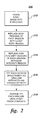
- Figure 3 is an illustration providing further detail of the method for removing "grid line artifacts" of the present invention.
- Figure 4 is a continuation of the method for removing "grid line artifacts" of Figure 3.
- Figure 5 is a continuation of the method for removing "grid line artifacts" of Figure 3.
- Figure 6 is a further illustration of
block 280 illustrated in Figure 4. - Figure 7 is an illustration of the spectral components of a Fourier transform of the typical x-ray image with "grid line artifacts".
- Figure 8 is an illustration of spectral components of the Fourier transform illustrated in Figure 7 having "grid line artifacts" modified by the method of the present invention.
- In a x-ray radiography imaging system, an x-ray source (not illustrated) projects a cone-shaped pattem of beams which pass through an
object 124 being imaged and impinge upon an array ofradiation detectors 130, as illustrated in Figure 1. Eachdetector 130 produces a separate electrical signal that is a measurement of incident beam attenuation. The attenuation measurements from alldetectors 130 are acquired separately to produce an x-ray image. A metallicanti-scatter grid 114 is typically placed against adetector base 112 to channel the x-rays so that only substantially perpendicular x-rays (e.g. rays 118 and 122) to a detector strike thedetector 130 and x-rays that are not substantially perpendicular (e.g. x-rays 116 and 120) are blocked byanti-scatter grid 114. Substantially perpendicular x-rays are those x-rays that strikedetector 130 and do not strikinganti-scatter grid 114. - In this Specification, "grid line artifacts" are defined as extraneous visible data in the x-ray image generated in association with the use of
anti-scatter grid 114,detector 130 electronics, and any other source which causes extraneous data to be seen in the x-ray image which result in high frequency spectral components having a spectral magnitude significantly greater than high frequency object data spectral components. Object data spectral components comprise those frequency components that result from the x-ray image and not from artifacts. - The method of removing "grid line artifacts" is illustrated by the method flowchart shown in Figure 2. This method includes: a
step 210, subdividing the x-ray image into a plurality of windows; astep 212, replacing regions with a substantial number of edges within each window with regions with less number of edges in the respective window; astep 214, replacing high intensity regions within each window with low intensity regions; astep 216, converting each window into the Fourier domain and removing "grid line artifacts"; and astep 218, conducting an inverse-Fourier transform on each window so that the modified x-ray image may be presented in a human readable format. Regions with a substantial number of edges hereinafter will be identified as "edgy regions" in this Specification. Edgy regions are further discussed below. - The x-ray image is divided into windows to facilitate computer based evaluation, as identified by the method of
step 210 in Figure 2. The window size is selected to be large enough to generate frequency resolution at about the expected frequency of the grid line artifact and alternatively, small enough to insure that the grid line artifact has a substantially constant spatial grid line frequency. The size of each window selected is such that it has substantially constant grid frequency. A grid frequency is considered substantially constant if there is at most one local maximum frequency component which is three standard deviations larger than the average value of the neighboring frequency components. For example, in a typical x-ray image having 1024 by 1024 pixels, the image may be divided into sixty-four windows. It is also understood that a window may have rectangular dimensions rather than square dimensions as illustrated in this case. - The "edgy region" of the x-ray image provides the necessary definition of object 124 (Figure 1) so that the human observer may easily identify important features of the x-ray as identified by the method of
step 212 in Figure 2. These features aid in diagnosis. For this reason it is important to preserve the detail of the "edgy region" of the x-ray image. The method employed in this invention preserves the "edgy regions" of the x-ray image by removing them before processing the image and replacing them after processing the image. "Edgy regions" are defined by the method identified below. - High intensity regions of the x-ray image are also removed before processing, as identified by the method of
step 214. This is necessary first to preserve the high intensity regions produced by the object and second, to facilitate removal of "grid line artifacts" in windows with high intensity regions. - Next, "grid line artifacts" are removed from the x-ray image, as identified by the method of
step 216. This is accomplished by converting the x-ray image to the Fourier domain where frequency components representing the x-ray image are generated, as illustrated bygraph 370 in Figure 7. In Figures 7 and 8 the vertical axis is defined as the frequency component magnitude, expressed in Decibels. The horizontal axis is defined as the frequency axis, expressed in Hertz. The frequency component of agrid line artifact 380 is distinguished from the frequency components of the image (e.g. components 372 - 378, and 382 - 386) in one respect in thatspectral component 380 is usually the highest spectral component of the high frequency components. As such, by eliminating low frequency components, (i.e. those components identified by range 371), the grid line artifact is usually the highest spectral component remaining, as is further discussed below. Grid linespectral component 380 is adjusted so thatcomponent 380 is no greater in magnitude than the average adjacent magnitude. The adjacent magnitude is defined byrange 388 as illustrated in Figure 7. - The x-ray image is then restored to a human readable format, as identified by the method of
step 218 of Figure 2. This is accomplished by conducting an inverse Fourier transform on the frequency components. It may also be necessary to adjust the mean value of the image, as is discussed below. -
Method 200 for removing "grid line artifacts" as shown in Figure 2, is presented in greater detail inmethod 250, as illustrated in Figure 3 through Figure 5. The steps identified in Figure 3 identify the method of generating a gradient image of the x-ray image and an intensity quantized image from the x-ray image. The gradient image is generated by first convolving the image with a gradient operator, as identified bystep 254. For digital images, such as those in this invention, gradient operators represent finite difference approximations of either the orthogonal gradient or the directional gradient. These masks are defined, for example, in the reference entitled, Fundamentals of Digital Image Processing, Anil K. Jain, Prentice Hall, 1989, chapter 9, pages 347 through 350.
Next, a histogram of the gradient image is computed, as identified bystep 260. From the histogram a threshold "T" is chosen such that a range of the pixels with the largest gradient are defined as edges, as identified bystep 262. For example, threshold value "T" may be selected from a range to identify about 10% to about 20 % of the pixels with the largest gradient. A gradient image is therefore generated using the threshold "T" to define edges, as identified bystep 266. - An intensity quantized image is generated by first computing an intensity histogram of the image, as identified by
step 270 in Figure 3. From this histogram a threshold "I" is chosen so that a fixed percentage of the pixels with the largest intensity are defined as high intensity regions, as identified bystep 258. Using threshold "I", an intensity quantized image is generated, as identified bystep 264. Regions with a low intensity are associated with a zero and regions with a high intensity are associated with a one. The ones and zeros are grouped together to define a matrix identified as the intensity quantized image. Intensity threshold "I" may be selected, for example, such that at most about 25% of the pixels with the largest intensity are defined as "high intensity regions." - The gradient image, intensity quantized image and x-ray image are all then divided into a plurality of number of respective windows as identified by
step 210. - Next, the mean value of each window is computed as identified by
step 274, in Figure 4. It is necessary to determine the mean value of the pixels of each window because mathematical manipulation as defined in subsequent operations within this Specification may change the mean value of the image within a respective window, resulting in undesirable artifacts. Thus, it may be necessary to adjust the mean value of each respective window so that the mean value of the respective window remains unchanged, as is discussed below. - The next step in
method 250 is to remove high frequency edges and high frequency intensity regions as identified by the method identified instep 280, in Figure 4. In order to remove "grid line artifacts" from the x-ray image it is first necessary to remove high frequency edges and high frequency intensity regions from each window, as discussed above.Block 280 is further subdivided into several sub-steps, as is identified by the method in Figure 6. - First, a window comprising a respective intensity window, gradient window, and x-ray window is subdivided into a plurality of sub-windows so that most sub-windows are substantially non-edgy, as identified by
sub-step 282, in Figure 6. For example, in an x-ray image having 1024 by 1024 pixels wherein sixty-four windows are selected, each window may be divided into sixty-four sub-windows. - Next, edgy sub-windows are replaced with the nearest non-edgy sub-windows based on the results from the test illustrated by the method in
sub-step 284. Where twenty or more percent of the gradient pixels of a sub-window are larger than threshold "T" the sub-window is replaced by the nearest non-edgy sub-window, as identified bysub-step 292. Non-edgy sub-windows are defined as those sub-windows wherein less than 20% of the gradient pixels are larger than threshold "T". The nearest sub-window is determined by comparing the distance between the center pixel of altemative sub-windows meeting the named criteria to the center pixel of the sub-window being replaced, then selecting the sub-window meeting the named criteria, and being closest in distance to the sub-window being replaced. - Following sub-step 292, high intensity sub-windows are replaced by low intensity sub-windows and sub-windows which are non-edgy, as defined by
sub-step 296. A high intensity sub-window is defined to be one in which 50% or more of the pixels have an associated intensity quantized number of one. When a high intensity sub-window is identified, as illustrated bysub-step 294, the high intensity sub-window is replaced by the nearest low intensity sub-window, as illustrated bysub-step 296. A low intensity sub-window is defined as a sub-window where less than 50% of the pixels in the intensity quantized sub-window are associated with a one and sub-windows which are non-edgy, as previously defined. This method is repeated until all sub-windows have been evaluated for high intensity regions and edgy regions, as identified bysub-step 298. - After edgy regions and high intensity regions have been removed from the image, "grid line artifacts" are removed, as identified by
steps 302 and 303, in Figure 4. Removing "grid line artifacts" is best illustrated by thegraphs typical graph 370 of the magnitudes of the frequency components of a Fourier transform of a respective window of the x-ray image having object data spectral components and grid line artifact spectral components. Grid line artifactspectral component 380 is distinguished from object data spectral components of the x-ray image window because grid linespectral component 380 is typically the high frequency component with largest magnitude. Grid line artifactspectral component 380 is the spectral component having a magnitude about three standard deviations greater than the average magnitude of the object data spectral components in arange 388.Range 388 is defined as the range of object data spectral components having substantially constant magnitudes. - Grid line
spectral component 380 is removed by first removing the low frequency spectral components in arange 371 ofgraph 370.Range 371 is defined as object data spectral component range having object data spectral component frequencies in the bottom ten percent of the spectral component frequency range.Component 380 is then removed as replaced by a newspectral component 381 that has a magnitude substantially equally to the average of adjacent spectral components identified inrange 388. This spectral component modification is illustrated bygraph 392 in Figure 8. - Although Figures 7 and 8 illustrate the grid line artifact spectral component removal method for a one-dimensional Fourier transform, a two-dimensional Fourier transform may be utilized to remove grid line artifact spectral components having "x" and "y" Cartesian coordinates. Steps in the two-dimensional method are substantially the same as those defined above in the one-dimensional method, with the primary difference being that spectral components have an "x" and a "y" coordinate defining each component's location, whereas in the one-dimensional Fourier transform magnitudes of the spectral component will only have one coordinate defining each component's location. The two-dimensional Fourier transform approach may be preferred over the one-dimensional Fourier transform approach if the grid-line artifacts are not perpendicular to the "x" and "y" co-ordinates of the image.
- The step of dividing the x-ray image into windows and variations in the mean value of the image within a window may cause noticeable artifacts known as a "ringing artifacts" along the periphery of a number of windows. "Ringing artifacts" occur because image data utilized in the Fourier transform is not infinite. Theoretically, a Fourier transform is a method of transforming data from the spatial domain to the frequency domain utilizing an infinite series, however, the x-ray images utilized in this invention have a finite number of windows and as such do not closely approximate an infinite series.
- Variations in the mean value of the pixels within each window may be removed by subtracting the error signal generated by calculating the mean value of the pixels within the initial window identified in
step 210, of Figure 2, and the mean value of the pixels of the modified window identified instep 218, of Figure 2, and then adjusting each modified window by subtracting the pixel mean value of the initial window from the pixel mean value of the modified window, as identified bystep 274, in Figure 4. The modified window is defined as the window in which "edgy regions," "high intensity regions" and "grid line artifacts" have been removed by the above-described method. - Next, "ringing artifacts" caused in part by dividing the x-ray image into widows may be eliminated by a method called "window substitution." In this method each respective window along the perimeter of a respective modified window are replaced by a equivalent respective modified window to generate a super-window. An equivalent respective modified window is defined as a copy of the respective modified window. The resulting super-window has nine identical modified windows.
Method 250 is then continued beginning atstep 302, in Figure 4, where the super-window is substituted for the modified window. Mathematical operations performed on the super-window causes ringing effects that normally would have appeared in the periphery of the modified window to appear in the outer periphery of the equivalent respective modified windows. Each respective equivalent modified window is discarded leaving only the modified window having no "ringing artifacts." - The x-ray image is restored next to a human readable format by performing an inverse Fourier transform converting the image from the frequency domain back into the original spatial domain image, as identified by the method of
step 218. Next, all edgy regions and high intensity regions that were replaced, as identified bysteps step 306, of Figure 5. - The windows are then equalized by subtracting the pixel mean value of the modified window from the pixel mean value of the initial window to generate a difference value, and multiplying the resulting difference value by each pixel in the modified image to obtain an adjusted modified image, as identified by
step 308, in Figure 5. - Finally, the steps of
method 250 described above are repeated for each window until all windows have been evaluated and processed according to the method described above as identified bysteps step 314, in Figure 5. - The present invention provides a method for removing "grid line artifacts" from an x-ray image. This method utilizes the Fourier spectrum of the image to detect grid line frequencies and employs a spectral domain filtering method to remove grid line spectral components. The diagnostic information is preserved by modifying the grid line spectral components so as to be indistinguishable from local variations and image intensity values and edge density of the x-ray image.
Claims (25)
- A method of removing grid line artifacts from an x-ray image having edgy regions, and high intensity regions, said method comprising the steps of:generating a gradient image and a intensity image from said x-ray image;replacing said edgy regions with non edgy regions to generate a modified x-ray image using said gradient image;replacing said high intensity regions with low intensity regions within said modified x-ray image using said intensity image;converting said modified x-ray image to the Fourier transform domain; andeliminating grid line artifacts from said modified x-ray image.
- The method as recited in claim 1, further comprising the step of eliminating ringing artifacts from said modified x-ray image after replacing said high intensity regions.
- The method as recited in claim 2, further comprising the step of restoring said modified image to a human readable format after eliminating ringing artifacts.
- The method as recited in claim 3, further comprising the step of dividing said x-ray image into a predetermined number of respective x-ray windows, dividing said gradient image into a predetermined number of gradient windows, and dividing said intensity image into a predetermined number of intensity windows before replacing said edgy regions and before replacing said high intensity regions.
- The method as recited in claim 4, wherein the step of dividing said image into intensity windows, gradient windows, and x-ray windows further comprises the step of dividing each respective intensity window, gradient window, and x-ray window into a predetermined number of respective sub-windows.
- The method as recited in claim 5, wherein the step of dividing said image into intensity windows, gradient windows, and x-ray windows further comprises the step of dividing each respective intensity window, gradient window, and x-ray window into sixty-four respective sub-windows.
- The method as recited in claim 5, wherein the step of generating said gradient image comprises the steps of:convolving said x-ray image with a gradient operator so as to generate a gradient image;computing a histogram of said gradient image; andchoosing a threshold value "T" so as to identify a predetermined range of pixels above the threshold value "T", wherein the pixels above threshold value "T" are edges.
- The method as recited in claim 7, wherein the step of replacing edgy regions further comprises the step of selecting threshold value "T" so that an edgy sub-window is identified when about ten percent to about twenty percent of pixels within said sub-window are above threshold value "T".
- The method as recited in claim 8, wherein the step of generating said gradient image further comprises the step of selecting said gradient operator to be a finite difference approximation of said respective orthogonal gradient.
- The method as recited in claim 9, wherein the step of generating said gradient image comprises the step of replacing each respective intensity window, gradient window, and x-ray window sub-windows with the nearest non-edgy sub-window when a respective gradient sub-window is edgy.
- The method as recited in claim 10, wherein the step of replacing edgy regions further comprises the step of selecting said predetermined percentage of gradient pixels to be about twenty percent.
- The method as recited in claim 5, wherein the step of replacing high intensity regions comprises the steps of:computing an intensity histogram of said image;choosing a threshold value "I" such that a predetermined percentage of pixels with the largest intensity is a high intensity region; andgenerating an intensity quantized image having high and low intensity regions.
- The method as recited in claim 12, wherein the step of replacing high intensity regions further comprises the step of replacing each one of said respective sub-window having a quantity of high intensity pixels greater than said predetermined intensity percentage with the respective nearest sub-window having a quantity of high intensity pixels less than said preselected intensity percentage.
- The method as recited in claim 13, wherein the step of replacing high intensity regions further comprises the step of selecting said predetermined intensity percentage to be about fifty percent.
- The method as recited in claim 14, wherein the step of converting said modified x-ray image to the frequency domain further comprises the step of removing ringing artifacts.
- The method as recited in claim 15, wherein the step of removing ringing artifacts comprises the step of replacing each adjacent window to a respective modified window with an equivalent modified window to generate a super-window.
- The method as recited in claim 16, wherein the step of converting said modified image to the frequency domain further comprises the step of converting said super-window to the Fourier transform domain so as to generate at least one object data spectral component and at least one grid line spectral component that corresponds to said modified x-ray image.
- The method as recited in claim 17, wherein the step of removing grid line artifacts comprise the steps of:selecting a respective one of said grid line artifact spectral components being situated adjacent to said at least one object data spectral component that is substantially lower in amplitude than said at least one grid line artifact component; andreplacing said at least one grid line artifact component with a replacement spectral component having an amplitude substantially equal to the average magnitude of said at least one object data spectral component.
- The method as recited in claim 18, where the step of removing grid line artifacts further comprises the step of selecting said grid line spectral component having a respective magnitude about three standard deviations greater than the average magnitude of said at least one object data spectral component.
- The method as recited in claim 19, wherein the step of restoring said modified image comprises the step of discarding each of said equivalent modified windows from said super-window.
- The method as recited in claim 20, wherein the step of restoring said modified image further comprises the step of restoring each of said edgy regions which were replaced.
- The method as recited in claim 21, wherein the step of restoring said modified image further comprises the step of restoring each of said high intensity regions which were replaced.
- The method as recited in claim 1, wherein the step of dividing said x-ray image into windows further comprises the step of calculating a pixel mean value of each respective window in said x-ray image.
- The method as recited in claim 23, wherein the step of restoring said modified image further comprises the step of equalizing the pixel mean value of each said respective window by adding the difference between the pixel mean value of each said respective restored modified window and the pixel mean value of each respective said window so as to equalize the mean value of said respective restored window to the mean value of said respective window.
- The method as recited in claim 1, wherein the step of dividing said x-ray image into a predetermined number of windows comprises the step of dividing said x-ray image into sixty-four windows.
Applications Claiming Priority (2)
| Application Number | Priority Date | Filing Date | Title |
|---|---|---|---|
| US88670 | 1998-06-02 | ||
| US09/088,670 US6333990B1 (en) | 1998-06-02 | 1998-06-02 | Fourier spectrum method to remove grid line artifacts without changing the diagnostic quality in X-ray images |
Publications (2)
| Publication Number | Publication Date |
|---|---|
| EP0962888A2 true EP0962888A2 (en) | 1999-12-08 |
| EP0962888A3 EP0962888A3 (en) | 2001-11-28 |
Family
ID=22212727
Family Applications (1)
| Application Number | Title | Priority Date | Filing Date |
|---|---|---|---|
| EP19990304304 Withdrawn EP0962888A3 (en) | 1998-06-02 | 1999-06-02 | Method for removing grid line artifacts in x-ray images |
Country Status (4)
| Country | Link |
|---|---|
| US (1) | US6333990B1 (en) |
| EP (1) | EP0962888A3 (en) |
| JP (1) | JP2000023954A (en) |
| CA (1) | CA2271798A1 (en) |
Cited By (17)
| Publication number | Priority date | Publication date | Assignee | Title |
|---|---|---|---|---|
| EP1265194A2 (en) * | 2001-05-01 | 2002-12-11 | Canon Kabushiki Kaisha | Method, system and program for processing and storing radiation images |
| WO2002100090A1 (en) * | 2001-06-07 | 2002-12-12 | Koninklijke Philips Electronics N.V. | System and method for removing sensitive data from diagnostic images |
| WO2003021294A1 (en) * | 2001-08-28 | 2003-03-13 | Ge Medical Systems Global Technology Company, Llc | Method and apparatus for identifying and correcting line artifacts in a solid state x-ray detector |
| FR2838852A1 (en) * | 2002-04-23 | 2003-10-24 | Ge Med Sys Global Tech Co Llc | Radiograph correction method for correcting for the effect of scattered X-ray photons in an image recorded with a collimated source, whereby the ratio of scattered to primary photons is determined and used to correct the image |
| EP1372108A2 (en) * | 2002-02-08 | 2003-12-17 | Eastman Kodak Company | Method for antiscatter stationary grid artifacts detection and attenuation in digital radiographic images |
| EP1126289A3 (en) * | 2000-02-04 | 2006-01-25 | Canon Kabushiki Kaisha | Image acquisition method and apparatus |
| EP1696366A1 (en) * | 2005-02-24 | 2006-08-30 | Agfa-Gevaert | Process of checking the presence of a grid pattern in an X-ray image |
| US7479969B2 (en) | 2005-02-24 | 2009-01-20 | Agfa Healthcare, N.V. | Grid detection method |
| NL1034578C2 (en) * | 2006-10-27 | 2009-04-15 | Ge Med Sys Global Tech Co Llc | X-ray tomography equipment and artifact reducing method. |
| US7894567B2 (en) | 2006-10-27 | 2011-02-22 | Ge Medical Systems Global Technology Company, Llc | X-ray tomography apparatus and artifact reducing method |
| CN104077743A (en) * | 2013-03-25 | 2014-10-01 | 深圳市蓝韵实业有限公司 | Suppression method and device for grid artifact in X-ray image |
| CN106651814A (en) * | 2017-01-12 | 2017-05-10 | 沈阳东软医疗系统有限公司 | Image processing method and apparatus |
| EP3236416A1 (en) * | 2016-04-19 | 2017-10-25 | Siemens Healthcare GmbH | Method for adjusting an x-ray image for effects of an anti-scatter grid, x-ray device, computer program and electronically readable data carrier |
| CN108009994A (en) * | 2017-10-25 | 2018-05-08 | 沈阳东软医疗系统有限公司 | A kind of bad wire restoration method, apparatus and equipment |
| CN108065944A (en) * | 2016-11-14 | 2018-05-25 | 上海西门子医疗器械有限公司 | The adaptation method and equipment and medical imaging system of flat panel detector and grid |
| RU189616U1 (en) * | 2018-12-29 | 2019-05-29 | Федеральное государственное автономное образовательное учреждение высшего образования "Балтийский федеральный университет имени Иммануила Канта" | DEVICE FOR SUPPRESSION OF SPECKLE STRUCTURE OF X-RAY IMAGES ON THE BASIS OF HIGH-DENSITY BERILLIUM |
| US11864932B2 (en) | 2020-12-14 | 2024-01-09 | Koninklijke Philips N.V. | X-ray imaging systems for reducing artefacts associated with anti-scatter grids and methods of operating the same |
Families Citing this family (27)
| Publication number | Priority date | Publication date | Assignee | Title |
|---|---|---|---|---|
| EP1120743B1 (en) * | 2000-01-20 | 2006-07-26 | Fuji Photo Film Co., Ltd. | Method and unit for suppressing a periodic pattern |
| JP4612754B2 (en) * | 2000-02-04 | 2011-01-12 | キヤノン株式会社 | Image acquisition apparatus and image acquisition method |
| US7065256B2 (en) * | 2001-02-08 | 2006-06-20 | Dblur Technologies Ltd. | Method for processing a digital image |
| JP2003150954A (en) * | 2001-11-14 | 2003-05-23 | Fuji Photo Film Co Ltd | Cyclic pattern restraining processing method and device |
| EP1527610A1 (en) * | 2002-07-31 | 2005-05-04 | Koninklijke Philips Electronics N.V. | Dynamic detection of blocking artefacts |
| US8294999B2 (en) | 2003-01-16 | 2012-10-23 | DigitalOptics Corporation International | Optics for an extended depth of field |
| US20070236573A1 (en) * | 2006-03-31 | 2007-10-11 | D-Blur Technologies Ltd. | Combined design of optical and image processing elements |
| JP4377404B2 (en) * | 2003-01-16 | 2009-12-02 | ディ−ブルアー テクノロジス リミテッド | Camera with image enhancement function |
| US7773316B2 (en) * | 2003-01-16 | 2010-08-10 | Tessera International, Inc. | Optics for an extended depth of field |
| JP3903027B2 (en) * | 2003-08-07 | 2007-04-11 | キヤノン株式会社 | Radiation image processing method and apparatus, and grid selection method and apparatus |
| US20060262902A1 (en) * | 2005-05-19 | 2006-11-23 | The Regents Of The University Of California | Security X-ray screening system |
| US7796792B2 (en) * | 2005-06-29 | 2010-09-14 | Agfa Healthcare, N.V. | Method of identifying disturbing frequencies originating from the presence of an anti-scatter grid during acquisition of a radiation image |
| US20070239417A1 (en) * | 2006-03-31 | 2007-10-11 | D-Blur Technologies Ltd. | Camera performance simulation |
| US20070236574A1 (en) * | 2006-03-31 | 2007-10-11 | D-Blur Technologies Ltd. | Digital filtering with noise gain limit |
| US8233675B2 (en) * | 2006-06-20 | 2012-07-31 | L-1 Secure Credentialing, Inc. | Image, video or audio filtering before biometric recognition |
| WO2009044452A1 (en) * | 2007-10-02 | 2009-04-09 | Shimadzu Corporation | Radiation image processor and radiation image processing program |
| US9968316B2 (en) | 2010-12-29 | 2018-05-15 | General Electric Company | High-frequency anti-scatter grid movement profile for line cancellation |
| JP5698577B2 (en) * | 2011-03-24 | 2015-04-08 | 富士フイルム株式会社 | Image processing apparatus, image processing method, and image processing program |
| JP5772523B2 (en) * | 2011-11-11 | 2015-09-02 | コニカミノルタ株式会社 | Medical image photographing system, medical image processing apparatus, and program |
| JP2013172880A (en) * | 2012-02-27 | 2013-09-05 | Fujifilm Corp | Periodic pattern detection device and method |
| JP5753505B2 (en) * | 2012-02-28 | 2015-07-22 | 富士フイルム株式会社 | Periodic pattern detection apparatus and method |
| US9148644B2 (en) * | 2012-12-14 | 2015-09-29 | Tektronix, Inc. | System for detecting structured artifacts in video sequences |
| JP2014176565A (en) * | 2013-03-15 | 2014-09-25 | Canon Inc | Image processor, radiographic apparatus, image processing method, computer program and recording medium |
| CN104574288B (en) * | 2013-10-22 | 2017-07-21 | 辽宁开普医疗系统有限公司 | A kind of adaptive grid artifact suppressing method and its device |
| KR101751750B1 (en) | 2015-10-16 | 2017-06-29 | 주식회사 레이언스 | Method for Correcting Defects in a Medical X-ray Image |
| CN107203983B (en) * | 2016-03-17 | 2024-03-22 | 通用电气公司 | Method and system for reducing grid line artifacts in X-ray images |
| CN107274350B (en) | 2016-04-07 | 2021-08-10 | 通用电气公司 | Method and system for reducing ringing effects in X-ray images |
Citations (2)
| Publication number | Priority date | Publication date | Assignee | Title |
|---|---|---|---|---|
| JPH0888765A (en) * | 1994-09-20 | 1996-04-02 | Konica Corp | Image reader |
| EP0792060A1 (en) * | 1989-04-11 | 1997-08-27 | Fuji Photo Film Co., Ltd. | Image Processing method |
Family Cites Families (11)
| Publication number | Priority date | Publication date | Assignee | Title |
|---|---|---|---|---|
| JPS61209641A (en) | 1985-03-15 | 1986-09-17 | 株式会社東芝 | X-ray ct apparatus |
| US5265142A (en) | 1992-05-08 | 1993-11-23 | General Electric Company | Image reconstruction technique for a computer tomography system |
| US5537485A (en) * | 1992-07-21 | 1996-07-16 | Arch Development Corporation | Method for computer-aided detection of clustered microcalcifications from digital mammograms |
| WO1994023390A1 (en) * | 1993-03-29 | 1994-10-13 | Matsushita Electric Industrial Co., Ltd. | Apparatus for identifying person |
| EP0627633A1 (en) * | 1993-05-18 | 1994-12-07 | Koninklijke Philips Electronics N.V. | Method and apparatus for magnetic resonance imaging |
| JPH07299053A (en) * | 1994-04-29 | 1995-11-14 | Arch Dev Corp | Computer diagnosis support method |
| US5572565A (en) * | 1994-12-30 | 1996-11-05 | Philips Electronics North America Corporation | Automatic segmentation, skinline and nipple detection in digital mammograms |
| US5933540A (en) * | 1995-05-11 | 1999-08-03 | General Electric Company | Filter system and method for efficiently suppressing noise and improving edge definition in a digitized image |
| AU5775696A (en) * | 1995-06-06 | 1996-12-24 | Beltronics Inc | Automatic protein and/or dna analysis system and method |
| US5923775A (en) * | 1996-04-04 | 1999-07-13 | Eastman Kodak Company | Apparatus and method for signal dependent noise estimation and reduction in digital images |
| IL118784A (en) * | 1996-07-03 | 1999-04-11 | Eliav Medical Imaging Systems | Method and apparatus for processing images for removal of artifacts |
-
1998
- 1998-06-02 US US09/088,670 patent/US6333990B1/en not_active Expired - Fee Related
-
1999
- 1999-05-13 CA CA 2271798 patent/CA2271798A1/en not_active Abandoned
- 1999-06-01 JP JP15317799A patent/JP2000023954A/en not_active Withdrawn
- 1999-06-02 EP EP19990304304 patent/EP0962888A3/en not_active Withdrawn
Patent Citations (2)
| Publication number | Priority date | Publication date | Assignee | Title |
|---|---|---|---|---|
| EP0792060A1 (en) * | 1989-04-11 | 1997-08-27 | Fuji Photo Film Co., Ltd. | Image Processing method |
| JPH0888765A (en) * | 1994-09-20 | 1996-04-02 | Konica Corp | Image reader |
Non-Patent Citations (2)
| Title |
|---|
| MICHITAKA HONDA ET AL: "A TECHNIQUE OF SCATTER-GLARE CORRECTION USING A DIGITAL FILTRATION" MEDICAL PHYSICS,US,AMERICAN INSTITUTE OF PHYSICS. NEW YORK, vol. 20, no. 1, 1993, pages 59-69, XP000345802 ISSN: 0094-2405 * |
| PATENT ABSTRACTS OF JAPAN vol. 1996, no. 08, 30 August 1996 (1996-08-30) & JP 08 088765 A (KONICA CORP), 2 April 1996 (1996-04-02) -& US 5 881 162 A ((ISHIMITSU YOSHIYUKI)) 9 March 1999 (1999-03-09) * |
Cited By (26)
| Publication number | Priority date | Publication date | Assignee | Title |
|---|---|---|---|---|
| EP1126289A3 (en) * | 2000-02-04 | 2006-01-25 | Canon Kabushiki Kaisha | Image acquisition method and apparatus |
| EP1265194A2 (en) * | 2001-05-01 | 2002-12-11 | Canon Kabushiki Kaisha | Method, system and program for processing and storing radiation images |
| EP1265194A3 (en) * | 2001-05-01 | 2012-10-24 | Canon Kabushiki Kaisha | Method, system and program for processing and storing radiation images |
| WO2002100090A1 (en) * | 2001-06-07 | 2002-12-12 | Koninklijke Philips Electronics N.V. | System and method for removing sensitive data from diagnostic images |
| US6823203B2 (en) | 2001-06-07 | 2004-11-23 | Koninklijke Philips Electronics N.V. | System and method for removing sensitive data from diagnostic images |
| WO2003021294A1 (en) * | 2001-08-28 | 2003-03-13 | Ge Medical Systems Global Technology Company, Llc | Method and apparatus for identifying and correcting line artifacts in a solid state x-ray detector |
| US6623161B2 (en) | 2001-08-28 | 2003-09-23 | Ge Medical Systems Global Technology Company, Llc | Method and apparatus for identifying and correcting line artifacts in a solid state X-ray detector |
| EP1372108A2 (en) * | 2002-02-08 | 2003-12-17 | Eastman Kodak Company | Method for antiscatter stationary grid artifacts detection and attenuation in digital radiographic images |
| EP1372108A3 (en) * | 2002-02-08 | 2004-05-19 | Eastman Kodak Company | Method for antiscatter stationary grid artifacts detection and attenuation in digital radiographic images |
| FR2838852A1 (en) * | 2002-04-23 | 2003-10-24 | Ge Med Sys Global Tech Co Llc | Radiograph correction method for correcting for the effect of scattered X-ray photons in an image recorded with a collimated source, whereby the ratio of scattered to primary photons is determined and used to correct the image |
| EP1696366A1 (en) * | 2005-02-24 | 2006-08-30 | Agfa-Gevaert | Process of checking the presence of a grid pattern in an X-ray image |
| US7479969B2 (en) | 2005-02-24 | 2009-01-20 | Agfa Healthcare, N.V. | Grid detection method |
| US7889833B2 (en) | 2006-10-27 | 2011-02-15 | Ge Medical Systems Global Technology Company, Llc | X-ray tomography apparatus and artifact reducing method |
| NL1034578C2 (en) * | 2006-10-27 | 2009-04-15 | Ge Med Sys Global Tech Co Llc | X-ray tomography equipment and artifact reducing method. |
| US7894567B2 (en) | 2006-10-27 | 2011-02-22 | Ge Medical Systems Global Technology Company, Llc | X-ray tomography apparatus and artifact reducing method |
| CN104077743A (en) * | 2013-03-25 | 2014-10-01 | 深圳市蓝韵实业有限公司 | Suppression method and device for grid artifact in X-ray image |
| US10159452B2 (en) | 2016-04-19 | 2018-12-25 | Siemens Healthcare Gmbh | Correction of an x-ray image for effects of an anti-scatter grid |
| EP3236416A1 (en) * | 2016-04-19 | 2017-10-25 | Siemens Healthcare GmbH | Method for adjusting an x-ray image for effects of an anti-scatter grid, x-ray device, computer program and electronically readable data carrier |
| CN108065944B (en) * | 2016-11-14 | 2021-10-22 | 上海西门子医疗器械有限公司 | Method and device for adapting flat panel detector and grid and medical imaging system |
| CN108065944A (en) * | 2016-11-14 | 2018-05-25 | 上海西门子医疗器械有限公司 | The adaptation method and equipment and medical imaging system of flat panel detector and grid |
| CN106651814A (en) * | 2017-01-12 | 2017-05-10 | 沈阳东软医疗系统有限公司 | Image processing method and apparatus |
| CN106651814B (en) * | 2017-01-12 | 2020-06-12 | 东软医疗系统股份有限公司 | Image processing method and device |
| CN108009994B (en) * | 2017-10-25 | 2020-08-04 | 东软医疗系统股份有限公司 | Bad line repairing method, device and equipment |
| CN108009994A (en) * | 2017-10-25 | 2018-05-08 | 沈阳东软医疗系统有限公司 | A kind of bad wire restoration method, apparatus and equipment |
| RU189616U1 (en) * | 2018-12-29 | 2019-05-29 | Федеральное государственное автономное образовательное учреждение высшего образования "Балтийский федеральный университет имени Иммануила Канта" | DEVICE FOR SUPPRESSION OF SPECKLE STRUCTURE OF X-RAY IMAGES ON THE BASIS OF HIGH-DENSITY BERILLIUM |
| US11864932B2 (en) | 2020-12-14 | 2024-01-09 | Koninklijke Philips N.V. | X-ray imaging systems for reducing artefacts associated with anti-scatter grids and methods of operating the same |
Also Published As
| Publication number | Publication date |
|---|---|
| EP0962888A3 (en) | 2001-11-28 |
| JP2000023954A (en) | 2000-01-25 |
| US6333990B1 (en) | 2001-12-25 |
| CA2271798A1 (en) | 1999-12-02 |
Similar Documents
| Publication | Publication Date | Title |
|---|---|---|
| US6333990B1 (en) | Fourier spectrum method to remove grid line artifacts without changing the diagnostic quality in X-ray images | |
| EP0777891B1 (en) | Image processing for noise reduction | |
| JP2551552B2 (en) | A method of displaying or recording an image in which details of the original image are emphasized | |
| EP2533197B1 (en) | Parameter-less noise reduction filter | |
| US5832055A (en) | Method of correcting a radiation image for defects in the recording member | |
| Giger et al. | Investigation of basic imaging properties in digital radiography. 7. Noise Wiener spectra of II–TV digital imaging systems | |
| US5617461A (en) | Method for the operation of a digital imaging system of an X-ray diagnostic apparatus | |
| EP0182423B1 (en) | Radiation image processing apparatus and method | |
| EP0610604A1 (en) | Multiple processing of radiographic images based on a pyramidal image decomposition | |
| Tapiovaara | SNR and noise measurements for medical imaging. II. Application to fluoroscopic x-ray equipment | |
| JP3662283B2 (en) | Visualization of diagnostically unrelated areas in the display of radiographic images | |
| EP0542361B1 (en) | Method and apparatus for constructing a histogram in digital image processing by statistical pixel sampling | |
| US6360025B1 (en) | Image processing method for reducing the noise in an image of a sequence of three temporal images, and medical imaging apparatus for carrying out such a method | |
| Zhang et al. | Automatic background recognition and removal (ABRR) in computed radiography images | |
| JPH0792588A (en) | Method for monitoring sensitivity of device for reading radiation image recorded in light stimulus fluorescent screen | |
| US8055052B2 (en) | Artifact suppression in diagnostic images | |
| JP2014176565A (en) | Image processor, radiographic apparatus, image processing method, computer program and recording medium | |
| JPS61133847A (en) | Promation of image clear of scattered line in x ray image | |
| Movafeghi et al. | Using nonlocal operators for measuring dimensions of defects in radiograph of welded objects | |
| EP0792061B1 (en) | Method for generating radiation image signals and radiation read-out apparatus | |
| JP6570594B2 (en) | Image processing apparatus, radiation imaging apparatus, image processing method, computer program, and storage medium | |
| EP0654762B1 (en) | Visualisation of diagnostically irrelevant zones in a radiographic image | |
| WO2009065441A1 (en) | Method and arrangement in fluoroscopy and ultrasound systems | |
| Georgieva et al. | Adaptive algorithm for CT images enhancement to improve the diagnosis of lung diseases | |
| Ishida | Iexample 2 |
Legal Events
| Date | Code | Title | Description |
|---|---|---|---|
| PUAI | Public reference made under article 153(3) epc to a published international application that has entered the european phase |
Free format text: ORIGINAL CODE: 0009012 |
|
| AK | Designated contracting states |
Kind code of ref document: A2 Designated state(s): AT BE CH CY DE DK ES FI FR GB GR IE IT LI LU MC NL PT SE Kind code of ref document: A2 Designated state(s): DE FR NL |
|
| AX | Request for extension of the european patent |
Free format text: AL;LT;LV;MK;RO;SI |
|
| PUAL | Search report despatched |
Free format text: ORIGINAL CODE: 0009013 |
|
| AK | Designated contracting states |
Kind code of ref document: A3 Designated state(s): AT BE CH CY DE DK ES FI FR GB GR IE IT LI LU MC NL PT SE |
|
| AX | Request for extension of the european patent |
Free format text: AL;LT;LV;MK;RO;SI |
|
| 17P | Request for examination filed |
Effective date: 20020528 |
|
| AKX | Designation fees paid |
Free format text: DE FR NL |
|
| 17Q | First examination report despatched |
Effective date: 20021203 |
|
| STAA | Information on the status of an ep patent application or granted ep patent |
Free format text: STATUS: THE APPLICATION IS DEEMED TO BE WITHDRAWN |
|
| 18D | Application deemed to be withdrawn |
Effective date: 20050920 |