EP0962385A1 - Sealing device and method for sealing packages - Google Patents
Sealing device and method for sealing packages Download PDFInfo
- Publication number
- EP0962385A1 EP0962385A1 EP99109571A EP99109571A EP0962385A1 EP 0962385 A1 EP0962385 A1 EP 0962385A1 EP 99109571 A EP99109571 A EP 99109571A EP 99109571 A EP99109571 A EP 99109571A EP 0962385 A1 EP0962385 A1 EP 0962385A1
- Authority
- EP
- European Patent Office
- Prior art keywords
- sealing tool
- sealing
- packaging
- parts
- tool according
- Prior art date
- Legal status (The legal status is an assumption and is not a legal conclusion. Google has not performed a legal analysis and makes no representation as to the accuracy of the status listed.)
- Withdrawn
Links
Images


Classifications
-
- B—PERFORMING OPERATIONS; TRANSPORTING
- B65—CONVEYING; PACKING; STORING; HANDLING THIN OR FILAMENTARY MATERIAL
- B65B—MACHINES, APPARATUS OR DEVICES FOR, OR METHODS OF, PACKAGING ARTICLES OR MATERIALS; UNPACKING
- B65B9/00—Enclosing successive articles, or quantities of material, e.g. liquids or semiliquids, in flat, folded, or tubular webs of flexible sheet material; Subdividing filled flexible tubes to form packages
- B65B9/02—Enclosing successive articles, or quantities of material between opposed webs
- B65B9/04—Enclosing successive articles, or quantities of material between opposed webs one or both webs being formed with pockets for the reception of the articles, or of the quantities of material
Definitions
- the present invention relates to a sealing tool for sealing a Packaging tray with a cover film.
- Packaging especially for food, plays an important role today ever increasing role in making foodstuffs more durable.
- the food will for packaging in a so-called packaging tray and the The packaging tray is then sealed gas-tight with a cover film by the Cover film is sealed to the edge of the packaging tray.
- the packaging troughs are usually semi-continuous in so-called Sealing stations sealed with a cover film.
- Sealing stations sealed with a cover film.
- the one with the Packing well filled with packaging material and the cover film in the sealing station transported.
- a first lower sealing tool lifted vertically from below and against second upper, heated sealing tool arranged above the cover film pressed. Due to the pressure and the temperature, the cover film and the edge the packaging trough, which are located between the sealing tools, sealed.
- the Sealing seam has a certain width and that the sealing seam in Located essentially in the middle of the edge of the packaging tray. After this The first sealing tool will be sealed below the one that has just been sealed Lowered packaging tray and the sealed packaging tray Cutting station transported.
- the object is achieved by providing a lower one Sealing tool for sealing a packaging tray with a cover film solved that from a lower part, side parts that cross and side parts that parallel are aligned with the transport direction of the packaging trays, where at least one side part aligned parallel to the direction of transport in its spatial position relative to the machine frame is fixed while the others Parts of the die can be moved vertically downwards.
- Both side parts aligned in parallel to the transport direction are preferably in FIG fixed their spatial position in relation to the machine frame.
- the side parts which in their Position unchanged from the machine frame, on its top a surface with a low coefficient of friction.
- This surface can either polished or coated with Teflon or the like.
- the side parts which are fixed in their spatial position, preferably taper from top to bottom, so that they can be used to seal packaging troughs can one or more parallel to the transport direction of the packaging have aligned undercut (s).
- a sealing tool according to the invention is preferably used to seal at least two packaging trays arranged side by side.
- Such one Sealing tool has in addition to the lower part, the side parts, the cross and the Side parts aligned parallel to the transport direction of the packaging trays are, in addition, preferably at least one middle part, which compared to the Machine frame is fixed in its spatial position.
- the side parts of such a sealing tool are preferably also opposite fixed the machine frame in its spatial position.
- the middle parts and the Side parts that remain unchanged in their position relative to the machine frame, a surface with a low coefficient of friction on its top.
- the surface can either be polished or coated with Teflon or the like.
- the central part and / or the side parts taper in their spatial location are fixed from top to bottom, so with them Packaging trays can be sealed that are parallel to one or more Have the undercut (e) aligned in the transport direction of the packaging.
- Another object of the present invention is to provide a method of sealing of packaging trays to provide the disadvantages of the stand which does not have technology.
- the present invention has the advantage that a packaging tray with a or more aligned parallel to the transport direction of the packaging tray Undercuts can be sealed with a cover film.
- Another advantage of Invention is that heavily loading packaging trays by the in its location spatially fixed side and / or middle part is supported and thus no longer sags, so that the sealing tool at the packaging tray Up and down no longer destroyed.
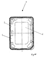
- Figure 1a shows a package with undercuts.
- the packaging 1 consists of a packaging trough 2 and a cover film 3.
- the packaging shown is a so-called stand-up packaging which stands with its narrow side on the surface shown.
- the stand-up packaging has undercuts 5 in order to stabilize the packaging in its erected position.
- Figure 1b shows the packaging according to Figure 1a in plan view.
- the undercuts 5 are located on one side of the packaging trough 2.
- the area shown in dark is the horizontal edge of the packaging trough onto which the cover film is sealed.
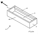
- FIG. 2a shows the sealing tool 6 according to the invention for sealing a packaging trough with a cover film.
- the sealing tool has a lower part 7, side parts 8, 9, the transverse and side parts 10, 11, which are aligned parallel to the transport direction of the packaging trays.
- the arrow shows the direction of transport of the sealed packaging trays.
- the side part 11 is thicker at the upper end than at the lower end, so that packaging troughs with an undercut on the side facing the side part 11 can be sealed with this sealing tool. If a packaging tray with two undercuts is to be sealed, the side part 10 can also be designed corresponding to the side part 11.
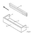
- FIG. 2b shows the sealing tool according to FIG. 2a after the lowering.
- the parts 7, 8, 9, 10 of the sealing tool are lowered, while the side part 11 remains fixed in its spatial position, so that the undercut facing the side part 11 is not damaged.
- the sealed packaging tray can then be transported in the direction of the arrow shown, parallel to the side part 11, without the undercut being damaged.
- FIG. 3a shows a sealing tool according to the invention for sealing two packaging trays with cover foils.
- this die has the middle parts 17, 17a.
- the middle part 17 tapers on both sides from top to bottom, so that with this sealing tool packaging troughs can be sealed, which have undercuts facing the middle part 17, 17a.
- the middle part 17a has a constant cross section.
- the person skilled in the art immediately recognizes that the middle parts 17 and 17a can also be manufactured as one part.
- the person skilled in the art also recognizes that the central part can also have a constant cross section overall. In this case, packages with an undercut could not be sealed.
- the middle part would then only serve to support the film between the packaging troughs so that they do not sag.
- the side parts 15 and 16 can also taper from top to bottom, so that packaging troughs can be sealed with this sealing tool, which have undercuts that face the side parts 15, 16.
- FIG. 3b shows the sealing tool according to FIG. 3a after the lowering.
- the parts 12, 13, 14, 15, 16 and 17a of the sealing tool are lowered, while the side part 17 is not lowered but remains fixed in its spatial position so that the undercuts facing the middle parts 17 and 17a are not damaged.
- the sealed packaging trays can then be transported in the direction of the arrow shown, parallel to the central part 17, without the undercuts of the packaging trays being damaged.
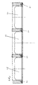
- FIG. 4 shows a section of the sealing tool according to the invention, the lower part and the side parts, which are oriented transversely to the transport direction of the packaging trays, being lowered, while the side parts 15, 16 and the two middle parts 17 are fixed in their spatial position.
- the packaging troughs 19, 20, 21 are supported in particular by the middle parts 17 from below, so that they do not sag.
- Figure 5 shows the sealing tool according to the invention for sealing two packaging trays with the associated lowering mechanism.
- the lower part 24 and the side parts 25 and 26 standing transversely to the transport direction of the packaging troughs can be seen from the sealing tool.
- the central part of the sealing tool can be seen, which consists of two parts 22 and 23. While the part 22 has a constant cross section, the part 23 tapers from top to bottom, so that packaging troughs with an undercut can be sealed with the central part.
- the part 23 is screwed onto the part 22 so that the shape of the undercut can be changed without great assembly effort.
- the central part is fastened to a rod 28, which in turn is firmly connected to the machine frame (not shown), so that the central part is fixed overall in its spatial position relative to the machine frame.
- the lower part of the sealing tool 24 is mounted on a plate 29 which has a drive (not shown) with which it is moved vertically up and down, as indicated by the double arrow.
- the plate 29 has a bore through which the
- FIG. 6 shows a sealing station with the sealing tool according to the invention.
- the packaging troughs 33 filled with packaging material and the cover film F2, which is unrolled from the roll V2, are transported to the sealing station and fixed there.
- the lowered parts 31 of the sealing tool according to the invention are pressed against the heated upper sealing tool 30.
- the cover film and the edge of the packaging trough, which are located between the sealing tool 31, 32 according to the invention and the sealing tool 30, are heated and thus sealed.
- the vertically displaceable parts 31 of the sealing tool are lowered again by the drives 35.
- the central part 32 is spatially fixed in position with a rod 34.
- the film and thus the just sealed packaging trays 33 are transported to the cutting station and then the vertically displaceable parts of the sealing tool are moved up again and the sealing process of the packaging tray can be carried out again.
Landscapes
- Engineering & Computer Science (AREA)
- Mechanical Engineering (AREA)
- Closing Of Containers (AREA)
- Package Closures (AREA)
- Containers And Plastic Fillers For Packaging (AREA)
Abstract
Description
Die vorliegende Erfindung betrifft ein Siegelwerkzeug zum Siegeln einer Verpackungsmulde mit einer Deckelfolie.The present invention relates to a sealing tool for sealing a Packaging tray with a cover film.
Verpackungen, insbesondere für Lebensmittel, spielen in der heutigen Zeit eine immer größere Rolle, um Lebensmittel haltbar zu machen. Die Lebensmittel werden zum Verpacken in eine sogenannte Verpackungsmulde gelegt und die Verpackungsmulde wird dann mit einer Deckelfolie gasdicht verschlossen, indem die Deckelfolie auf den Rand der Verpackungsmulde gesiegelt wird.Packaging, especially for food, plays an important role today ever increasing role in making foodstuffs more durable. The food will for packaging in a so-called packaging tray and the The packaging tray is then sealed gas-tight with a cover film by the Cover film is sealed to the edge of the packaging tray.
Die Verpackungsmulden werden in der Regel semikontinuierlich in sogenannten Siegelstationen mit einer Deckelfolie gesiegelt. Dafür werden zunächst die mit dem Verpackungsgut gefüllte Verpackungsmulde und die Deckelfolie in die Siegelstation transportiert. Sobald sich die Verpackungsmulde in der Siegelstation befindet, wird von unten ein erstes unteres Siegelwerkzeug vertikal angehoben und gegen ein zweites oberes, über der Deckelfolie angeordnetes, beheiztes Siegelwerkzeug gepreßt. Durch den Druck und die Temperatur werden die Deckelfolie und der Rand der Verpackungsmulde, die sich zwischen den Siegelwerkzeugen befinden, gesiegelt. Um eine gasdichte Siegelnaht zu erhalten, ist es wichtig, daß die Siegelnaht eine gewisse Breite aufweist und daß sich die Siegelnaht im Wesentlichen in der Mitte des Randes der Verpackungsmulde befindet. Nach dem Siegeln wird das erste Siegelwerkzeug wieder unterhalb die gerade gesiegelte Verpackungsmulde abgesenkt und die gesiegelte Verpackungsmulde zur Schneidestation weitertransportiert.The packaging troughs are usually semi-continuous in so-called Sealing stations sealed with a cover film. For this, the one with the Packing well filled with packaging material and the cover film in the sealing station transported. As soon as the packaging tray is in the sealing station a first lower sealing tool lifted vertically from below and against second upper, heated sealing tool arranged above the cover film pressed. Due to the pressure and the temperature, the cover film and the edge the packaging trough, which are located between the sealing tools, sealed. In order to obtain a gas-tight sealing seam, it is important that the Sealing seam has a certain width and that the sealing seam in Located essentially in the middle of the edge of the packaging tray. After this The first sealing tool will be sealed below the one that has just been sealed Lowered packaging tray and the sealed packaging tray Cutting station transported.
Obwohl sich diese Art der Siegelstation seit vielen Jahren im Einsatz befindet, weist sie dennoch einige Nachteile auf. So können Verpackungsmulden mit einem Hinterschnitt, mit einem solchen Siegelwerkzeug nicht gesiegelt werden, weil das erste Siegelwerkzeuge beim Anheben bzw. Absenken gegen diesen Hinterschnitt stößt und diesen zerstört. Aber auch bei Verpackungen ohne Hinterschnitt kommt es beim Siegeln von schwer beladenen Verpackungsmulden immer wieder zu Problemen, weil die Verpackungsmulden durchhängen. Durch dieses Durchhängen stellen sich die Verpackungsmulden schräg und das hochfahrende erste Siegelwerkzeug stößt gegen deren Ecken und zerstört oder deformiert diese.Although this type of sealing station has been in use for many years, they still have some drawbacks. So packaging troughs with one Undercut, can not be sealed with such a sealing tool, because that first sealing tools when lifting or lowering against this undercut bumps and destroys it. But it also happens with packaging without an undercut when sealing heavily loaded packaging trays again and again Problems because the packaging troughs sag. By this sagging the packaging troughs stand at an angle and the ramping up first Sealing tool pushes against their corners and destroys or deforms them.
Es stellt sich deshalb die Aufgabe, eine Vorrichtung zur Verfügung zu stellen, mit der eine Verpackungsmulde mit einem Hinterschnitt gesiegelt werden kann und die die anderen Nachteile des Standes der Technik nicht aufweist.It is therefore the task of providing a device with which a packaging tray with an undercut can be sealed and the does not have other disadvantages of the prior art.
Die Aufgabe wird erfindungsgemäß durch die Bereitstellung eines unteren Siegelwerkzeuges zum Siegeln einer Verpackungsmulde mit einer Deckelfolie gelöst, das aus einem Unterteil, Seitenteilen, die quer und Seitenteilen, die parallel zur Transportrichtung der Verpackungsmulden ausgerichtet sind, besteht, wobei mindestens ein parallel zur Transportrichtung ausgerichtetes Seitenteil in seiner räumlichen Lage gegenüber dem Maschinenrahmen fixiert ist, während die anderen Teile der Matrize vertikal nach unten verschiebbar sind.The object is achieved by providing a lower one Sealing tool for sealing a packaging tray with a cover film solved that from a lower part, side parts that cross and side parts that parallel are aligned with the transport direction of the packaging trays, where at least one side part aligned parallel to the direction of transport in its spatial position relative to the machine frame is fixed while the others Parts of the die can be moved vertically downwards.
In seiner räumlichen Lage gegenüber dem Maschinenrahmen fixiert bedeutet im Sinne der Erfindung nicht, daß das Teil völlig starr angeordnet sein muß. Es kann sich durchaus um einige Millimeter bewegen.Fixed in its spatial position in relation to the machine frame means im Does not mean the invention that the part must be arranged completely rigid. It can move quite a few millimeters.
Vorzugsweise sind beide parallel zur Transportrichtung ausgerichteten Seitenteile in ihrer räumlichen Lage gegenüber dem Maschinenrahmen fixiert.Both side parts aligned in parallel to the transport direction are preferably in FIG fixed their spatial position in relation to the machine frame.
In einer weiteren bevorzugten Ausführungsform weisen die Seitenteile, die in ihrer Lage gegenüber dem Maschinenrahmen unverändert bleiben, an ihrer Oberseite eine Oberfläche mit einem geringen Reibkoeffizienten auf. Diese Oberfläche kann entweder poliert oder mit Teflon oder ähnlichem beschichtet sein.In a further preferred embodiment, the side parts, which in their Position unchanged from the machine frame, on its top a surface with a low coefficient of friction. This surface can either polished or coated with Teflon or the like.
Vorzugsweise verjüngen sich die Seitenteile, die in ihrer räumlichen Lage fixiert sind von oben nach unten, so daß mit ihnen Verpackungsmulden gesiegelt werden können, die einen oder mehrere parallel zur Transportrichtung der Verpackung ausgerichtete Hinterschnitt(e) aufweisen.The side parts, which are fixed in their spatial position, preferably taper from top to bottom, so that they can be used to seal packaging troughs can one or more parallel to the transport direction of the packaging have aligned undercut (s).
Ein erfindungsgemäßes Siegelwerkzeug dient vorzugsweise zum Siegeln von mindestens zwei nebeneinander angeordneten Verpackungsmulden. Eine solches Siegelwerkzeug weist neben dem Unterteil, den Seitenteilen, die quer und den Seitenteilen, die parallel zur Transportrichtung der Verpackungsmulden ausgerichtet sind, zusätzlich vorzugsweise mindestens ein Mittelteil auf, das gegenüber dem Maschinenrahmen in seiner räumlichen Lage fixiert ist.A sealing tool according to the invention is preferably used to seal at least two packaging trays arranged side by side. Such one Sealing tool has in addition to the lower part, the side parts, the cross and the Side parts aligned parallel to the transport direction of the packaging trays are, in addition, preferably at least one middle part, which compared to the Machine frame is fixed in its spatial position.
Vorzugsweise sind auch die Seitenteile eines solchen Siegelwerkzeuges gegenüber dem Maschinenrahmen in seiner räumlichen Lage fixiert.The side parts of such a sealing tool are preferably also opposite fixed the machine frame in its spatial position.
In einer weiteren bevorzugten Ausführungsform weisen die Mittelteile und die Seitenteile, die in ihrer Lage gegenüber dem Maschinenrahmen unverändert bleiben, an ihrer Oberseite eine Oberfläche mit einem geringen Reibkoeffizienten auf. Diese Oberfläche kann entweder poliert oder mit Teflon oder ähnlichem beschichtet sein. Vorzugsweise verjüngen sich das Mittelteil und/oder die Seitenteile, die in ihrer räumlichen Lage fixiert sind von oben nach unten, so daß mit ihnen Verpackungsmulden gesiegelt werden können, die einen oder mehrere parallel zur Transportrichtung der Verpackung ausgerichtete Hinterschnitt(e) aufweisen.In a further preferred embodiment, the middle parts and the Side parts that remain unchanged in their position relative to the machine frame, a surface with a low coefficient of friction on its top. This The surface can either be polished or coated with Teflon or the like. Preferably, the central part and / or the side parts taper in their spatial location are fixed from top to bottom, so with them Packaging trays can be sealed that are parallel to one or more Have the undercut (e) aligned in the transport direction of the packaging.
Eine weitere Aufgabe der vorliegenden Erfindung ist es, ein Verfahren zum Siegeln von Verpackungsmulden zur Verfügung zu stellen, das die Nachteile des Standes der Technik nicht aufweist.Another object of the present invention is to provide a method of sealing of packaging trays to provide the disadvantages of the stand which does not have technology.
Diese Aufgabe wird erfindungsgemäß durch die Bereitstellung eines Verfahrens zum Siegeln einer Verpackungsmulde mit einer Deckelfolie unter Verwendung des erfindungsgemäßen Siegelwerkzeugs gelöst, wobei
- die Deckelfolie und die Verpackungsmulde in die Siegelstation transportiert und gegebenenfalls fixiert und zwischen das untere Siegelwerkzeug und das obere Siegelwerkzeug gepreßt, erhitzt und dabei gesiegelt werden,
- die vertikal verschiebbaren Teile des unteren Siegelwerkzeuges vertikal abgesenkt werden und
- die fertiggestellte Verpackung weitertransportiert wird.
- the lid film and the packaging tray are transported to the sealing station and, if necessary, fixed and pressed, heated and sealed between the lower sealing tool and the upper sealing tool,
- the vertically displaceable parts of the lower sealing tool are lowered vertically and
- the completed packaging is transported on.
Die vorliegende Erfindung hat den Vorteil, daß eine Verpackungsmulde mit einer oder mehreren parallel zur Transportrichtung der Verpackungsmulde ausgerichteten Hinterschnitten mit einer Deckelfolie gesiegelt werden kann. Ein weiterer Vorteil der Erfindung besteht darin, daß schwer beladende Verpackungsmulden durch das in seiner Lage räumlich fixierte Seiten- und/oder Mittelteil unterstützt wird und damit nicht mehr durchhängt, so daß das Siegelwerkzeug die Verpackungsmulde beim Hoch- und Runterfahren nicht mehr zerstört. The present invention has the advantage that a packaging tray with a or more aligned parallel to the transport direction of the packaging tray Undercuts can be sealed with a cover film. Another advantage of Invention is that heavily loading packaging trays by the in its location spatially fixed side and / or middle part is supported and thus no longer sags, so that the sealing tool at the packaging tray Up and down no longer destroyed.
Die Erfindung wird im folgenden anhand der Figuren 1-6 erläutert. Diese
Erläuterung ist lediglich beispielhaft und schränkt somit die Erfindung nicht ein.
Die Figur 1a zeigt eine Verpackung mit Hinterschnitten. Die Verpackung 1 besteht
aus einer Verpackungsmulde 2 und einer Deckelfolie 3. Bei der dargestellten
Verpackung handelt es sich um eine sogenannte Stand-up Verpackung, die mit ihrer
schmalen Seite auf der gezeigten Fläche steht. Die Stand-up Verpackung weist
Hinterschnitte 5 auf, um die Verpackung in ihrer aufgestellten Lage zu stabilisieren. Figure 1a shows a package with undercuts. The
Figur 1b zeigt die Verpackung gemäß Figur 1a in Draufsicht. An einer Seite der
Verpackungsmulde 2 befinden sich die Hinterschnitte 5. Der dunkel dargestellte
Bereich ist der horizontale Rand der Verpackungsmulde auf den die Deckelfolie
gesiegelt wird. Figure 1b shows the packaging according to Figure 1a in plan view. The
In Figur 2a ist das erfindungsgemäße Siegelwerkzeug 6 zum Siegeln einer
Verpackungsmulde mit einer Deckelfolie dargestellt. Das Siegelwerkzeug weist ein
Unterteil 7, Seitenteile 8, 9, die quer und Seitenteile 10, 11, die parallel zur
Transportrichtung der Verpackungsmulden ausgerichtet sind, auf. Der Pfeil zeigt die
Transportrichtung der gesiegelten Verpackungsmulden an. Das Seitenteil 11 ist am
oberen Ende dicker als am unteren Ende, so daß mit diesem Siegelwerkzeug
Verpackungsmulden mit einem Hinterschnitt auf der dem Seitenteil 11 zugewandten
Seite gesiegelt werden können. Wenn eine Verpackungsmulde mit zwei
Hinterschnitten gesiegelt werden soll, so kann auch das Seitenteil 10 entsprechend
dem Seitenteil 11 ausgebildet sein. FIG. 2a shows the sealing tool 6 according to the invention for sealing a packaging trough with a cover film. The sealing tool has a
In Figur 2b ist das Siegelwerkzeug gemäß Figur 2a nach dem Absenken dargestellt.
Nach dem Siegeln werden die Teile 7, 8, 9, 10 des Siegelwerkzeuges abgesenkt,
während das Seitenteil 11 in seiner räumlichen Lage fixiert bleibt, damit der dem
Seitenteil 11 zugewandte Hinterschnitt nicht beschädigt wird. Die gesiegelte
Verpackungsmulde kann dann in Richtung des dargestellten Pfeiles, parallel zum
Seitenteil 11 weitertransportiert werden, ohne daß der Hinterschnitt Schaden nimmt. 2b shows the sealing tool according to FIG. 2a after the lowering. After sealing, the
In Figur 3a ist ein erfindungsgemäßes Siegelwerkzeug zum Siegeln von zwei
Verpackungsmulden mit Deckelfolien dargestellt. Neben der Unterseite 12, den
Seitenteilen 13, 14, die quer und Seitenteile 15, 16, die parallel zur Transportrichtung
der Verpackungsmulden ausgerichtet sind, weist diese Matrize die Mittelteile 17, 17a
auf. Das Mittelteil 17 verjüngt sich auf beiden Seiten von oben nach unten, so daß
mit diesem Siegelwerkzeug Verpackungsmulden gesiegelt werden können, die
Hinterschnitte aufweisen, die dem Mittelteil 17, 17a zugewandt sind. Das Mittelteil
17a weist einen konstanten Querschnitt auf. Der Fachmann erkennt sofort, daß die
Mittelteile 17 und 17a auch als ein Teil gefertigt werden können. Ferner erkennt der
Fachmann, daß das Mittelteil auch insgesamt einen konstanten Querschnitt
aufweisen kann. In diesem Fall könnten keine Verpackungen mit einem Hinterschnitt
gesiegelt werden. Das Mittelteil würde dann lediglich zur Unterstützung der Folie
zwischen den Verpackungsmulden dienen, damit diese nicht durchhängt.
Selbstverständlich können sich auch die Seitenteile 15 und 16 von oben nach unten
verjüngen, so daß mit diesem Siegelwerkzeug Verpackungsmulden gesiegelt werden
können, die Hinterschnitte aufweisen, die den Seitenteilen 15, 16 zugewandt sind. FIG. 3a shows a sealing tool according to the invention for sealing two packaging trays with cover foils. In addition to the
In Figur 3b ist das Siegelwerkzeug gemäß Figur 3a nach dem Absenken dargestellt.
Nach dem Siegeln werden die Teile 12, 13, 14, 15, 16 und 17a des
Siegelwerkzeuges abgesenkt, während das Seitenteil 17 nicht abgesenkt wird
sondern in seiner räumlichen Lage fixiert bleibt, damit die mit den Mittelteilen 17 und
17a zugewandten Hinterschnitte nicht beschädigt werden. Die gesiegelten
Verpackungsmulden können dann in Richtung des dargestellten Pfeiles, parallel zum
Mittelteil 17 weitertransportiert werden, ohne daß die Hinterschnitte der
Verpackungsmulden Schaden nehmen. FIG. 3b shows the sealing tool according to FIG. 3a after the lowering. After sealing, the
In Figur 4 ist ein Schnitt des erfindungsgemäßen Siegelwerkzeugs dargestellt,
wobei das Unterteil und die Seitenteile, die quer zur Transportrichtung der
Verpackungsmulden ausgerichtet sind, abgesenkt worden sind, während die
Seitenteile 15, 16 und die zwei Mittelteile 17 in ihrer räumlichen Lage fixiert sind. Die
Verpackungsmulden 19, 20, 21 werden insbesondere durch die Mitteltteile 17 von
unten unterstützt, so daß sie nicht durchhängen. FIG. 4 shows a section of the sealing tool according to the invention, the lower part and the side parts, which are oriented transversely to the transport direction of the packaging trays, being lowered, while the
Figur 5 zeigt das erfindungsgemäße Siegelwerkzeug zum Siegeln von zwei
Verpackungsmulden mit dem dazugehörigen Absenkmechanismus. Von dem
Siegelwerkzeug sind das Unterteil 24 und die quer zur Transportrichtung der
Verpackungsmulden stehenden Seitenteile 25 und 26 zu sehen. Ferner ist das
Mittelteil des Siegelwerkzeugs zu sehen, das aus zwei Teilen 22 und 23 besteht.
Während das Teil 22 einen konstanten Querschnitt aufweist, verjüngt sich das Teil
23 von oben nach unten, so daß mit dem Mittelteil Verpackungsmulden mit einem
Hinterschnitte gesiegelt werden können. Das Teil 23 ist auf das Teil 22 geschraubt,
so daß die Form des Hinterschnittes ohne großen Montageaufwand verändert
werden kann. Das Mittelteil ist an einer Stange 28 befestigt, die ihrerseits fest mit
dem Maschinenrahmen (nicht dargestellt) verbunden ist, so daß das Mittelteil
insgesamt in seiner räumlichen Lage gegenüber dem Maschinenrahmen fixiert ist.
Das Unterteil des Siegelwerkzeugs 24 ist auf einer Platte 29 montiert, die über einen
Antrieb (nicht dargestellt) verfügt, mit dem sie, wie durch den Doppelpfeil
angedeutet, vertikal hoch und runter bewegt wird. Die Platte 29 weist eine Bohrung
auf durch die die Stange 28 geführt wird. Figure 5 shows the sealing tool according to the invention for sealing two packaging trays with the associated lowering mechanism. The
Falls auch die parallel zur Transportrichtung stehenden Seitenteile in ihrer Lage gegenüber dem Maschinenrahmen fixiert sein sollen werden diese ebenfalls mit Stangen gehalten. Der Fachmann erkennt, daß das Mittelteil auch auf jede andere Weise fixiert werden kann.If the side parts parallel to the transport direction are in their position they should also be fixed in relation to the machine frame Poles held. Those skilled in the art will recognize that the middle section can also be attached to any other Way can be fixed.
Figur 6 zeigt eine Siegelstation mit der erfindungsgemäßen Siegelwerkzeug. Die mit
Verpackungsgut gefüllten Verpackungsmulden 33 und die Deckfolie F2, die von der
Rolle V2 abgerollt wird, werden in die Siegelstation transportiert und dort fixiert.
Sobald die Verpackungsmulde und die Deckelfolie fixiert sind, werden die
abgesenkten Teile 31 des erfindungsgemäßen Siegelwerkzeugs und gegen das
beheizte obere Siegelwerkzeug 30 gepreßt. Die Deckelfolie und der Rand der
Verpackungsmulde, die sich zwischen dem erfindungsgemäßen Siegelwerkzeug 31,
32 und dem Siegelwerkzeug 30 befinden, werden erhitzt und somit gesiegelt. Nach
dem Siegeln werden die vertikal verschiebbaren Teile 31 des Siegelwerkzeugs
durch die Antriebe 35 wieder abgesenkt. Das Mittelteil 32 wird mit einer Stange 34 in
seiner Lage räumlich fixiert. Nach dem Absenken der vertikal verschiebbaren Teile
31 des Siegelwerkzeugs, wird die Folie und damit die gerade gesiegelten
Verpackungsmulden 33 zur Schneidstation weitertransportiert und danach werden
die vertikal verschiebbaren Teile des Siegelwerkzeugs wieder nach oben bewegt und
der Siegelvorgang der Verpackungsmulde kann erneut durchgeführt werden. FIG. 6 shows a sealing station with the sealing tool according to the invention. The
Claims (10)
Applications Claiming Priority (2)
| Application Number | Priority Date | Filing Date | Title |
|---|---|---|---|
| DE19824589A DE19824589A1 (en) | 1998-06-02 | 1998-06-02 | Sealing tool and method for sealing packaging |
| DE19824589 | 1998-06-02 |
Publications (1)
| Publication Number | Publication Date |
|---|---|
| EP0962385A1 true EP0962385A1 (en) | 1999-12-08 |
Family
ID=7869649
Family Applications (1)
| Application Number | Title | Priority Date | Filing Date |
|---|---|---|---|
| EP99109571A Withdrawn EP0962385A1 (en) | 1998-06-02 | 1999-05-14 | Sealing device and method for sealing packages |
Country Status (4)
| Country | Link |
|---|---|
| US (2) | US6240706B1 (en) |
| EP (1) | EP0962385A1 (en) |
| DE (1) | DE19824589A1 (en) |
| ES (1) | ES2141698T1 (en) |
Families Citing this family (9)
| Publication number | Priority date | Publication date | Assignee | Title |
|---|---|---|---|---|
| ES2270730B2 (en) * | 2006-03-14 | 2013-07-05 | Jorge LÓPEZ RODRIGUEZ | BARRENOS DRAIN PUMP THROUGH ALTERNATIVE CYCLES OF SUCTION AND EXPULSION BASED ON THE PRICE OF PNEUMATIC DISPLACEMENT |
| US7340871B1 (en) * | 2006-03-31 | 2008-03-11 | Alkar-Rapidpak, Inc. | Web packaging system with ergonomic tooling change |
| US7703265B2 (en) * | 2007-10-23 | 2010-04-27 | Alkar-Rapidpak, Inc. | Web packaging system with ergonomic forming plug change |
| DE102007062983A1 (en) * | 2007-12-21 | 2009-06-25 | Ulma Packaging Gmbh | packaging machine |
| DE102008019628A1 (en) * | 2008-04-18 | 2009-11-05 | Multivac Sepp Haggenmüller Gmbh & Co. Kg | packaging machine |
| WO2010111237A1 (en) * | 2009-03-24 | 2010-09-30 | Peerless Machine & Tool Corporation | Cup lid manufacturing process |
| US8499536B2 (en) | 2009-05-18 | 2013-08-06 | Alkar-Rapidpak-Mp Equipment, Inc. | Apparatuses and methods for assisted tooling extraction |
| US8186134B2 (en) * | 2009-05-18 | 2012-05-29 | Alkar-Rapidpak-Mp Equipment, Inc. | Packaging machines and methods |
| US9156573B2 (en) | 2011-03-30 | 2015-10-13 | Alkar-Rapidpak, Inc. | Packaging apparatuses and methods |
Citations (3)
| Publication number | Priority date | Publication date | Assignee | Title |
|---|---|---|---|---|
| GB886531A (en) * | 1957-06-14 | 1962-01-10 | Kurt Ott | Improvements in or relating to packing apparatus |
| GB1185150A (en) * | 1966-09-12 | 1970-03-18 | Inst Nahrungsmittel Genussmitt | Making Packages by Moulding and Filling Plastics Containers |
| FR2528386A1 (en) * | 1982-06-14 | 1983-12-16 | Erca Holding | METHOD AND INSTALLATION OF PACKAGING A PRODUCT |
Family Cites Families (8)
| Publication number | Priority date | Publication date | Assignee | Title |
|---|---|---|---|---|
| DE59503C (en) | M. PIGOT in Brüssel | Horseshoe with cork inlay | ||
| DD59503A (en) * | ||||
| FR2648432B1 (en) * | 1989-06-16 | 1991-09-13 | Mecaplastic | DEVICE AND INSTALLATION FOR THE PACKAGING OF ANY PRODUCTS, FOR EXAMPLE OF FOOD PRODUCTS, IN TRAYS CLOSED BY A WELDED CLOSURE FILM |
| DE9006292U1 (en) * | 1990-06-02 | 1990-09-06 | Stiegler GmbH Maschinenfabrik, 7062 Rudersberg | Device for transverse welding and transverse cutting or transverse perforating a plastic film web |
| DE9113290U1 (en) * | 1991-10-25 | 1991-12-19 | Krämer + Grebe GmbH & Co KG Maschinenfabrik, 3560 Biedenkopf | Device for producing a packaging |
| US5241801A (en) * | 1992-08-31 | 1993-09-07 | Highland Plastics, Inc. | Container lid mounting and sealing system |
| US5765343A (en) * | 1995-10-20 | 1998-06-16 | Whittaker; Dale | Individual dental floss packaging method and apparatus |
| DE19541983A1 (en) * | 1995-11-10 | 1997-05-15 | Zahoransky Anton Gmbh & Co | Packing machine for packing toothbrush in blister pack |
-
1998
- 1998-06-02 DE DE19824589A patent/DE19824589A1/en not_active Withdrawn
-
1999
- 1999-05-14 EP EP99109571A patent/EP0962385A1/en not_active Withdrawn
- 1999-05-14 ES ES99109571T patent/ES2141698T1/en active Pending
- 1999-05-25 US US09/318,152 patent/US6240706B1/en not_active Expired - Fee Related
-
2000
- 2000-10-11 US US09/686,376 patent/US6260334B1/en not_active Expired - Fee Related
Patent Citations (3)
| Publication number | Priority date | Publication date | Assignee | Title |
|---|---|---|---|---|
| GB886531A (en) * | 1957-06-14 | 1962-01-10 | Kurt Ott | Improvements in or relating to packing apparatus |
| GB1185150A (en) * | 1966-09-12 | 1970-03-18 | Inst Nahrungsmittel Genussmitt | Making Packages by Moulding and Filling Plastics Containers |
| FR2528386A1 (en) * | 1982-06-14 | 1983-12-16 | Erca Holding | METHOD AND INSTALLATION OF PACKAGING A PRODUCT |
Also Published As
| Publication number | Publication date |
|---|---|
| US6240706B1 (en) | 2001-06-05 |
| US6260334B1 (en) | 2001-07-17 |
| ES2141698T1 (en) | 2000-04-01 |
| DE19824589A1 (en) | 1999-12-09 |
Similar Documents
| Publication | Publication Date | Title |
|---|---|---|
| DE69104172T2 (en) | Method and device for positioning a cover film web before it is sealed to a container unit. | |
| DE2816437B1 (en) | Device for automatically filling the edge joints of insulating glass panes with a sealant by filling nozzles | |
| DE2209845A1 (en) | Measuring device, in particular storage for measuring sensors | |
| DE69508636T2 (en) | Device for handling and cutting flat material on a vacuum table with a device for sealing the end areas of the table | |
| EP0962385A1 (en) | Sealing device and method for sealing packages | |
| DE2349767A1 (en) | DEVICE FOR AUTOMATIC APPLICATION OF COVER GLASSES | |
| DE69305271T2 (en) | Sealing device for boxes with two sealing units arranged one above the other and simplified access to the lower sealing unit | |
| EP0633186B1 (en) | Method and apparatus for wrapping products | |
| DE4424845C2 (en) | Cover plate for vacuum molding machines | |
| DE10033246A1 (en) | Press device for multi-sided coating of workpieces, especially furniture parts | |
| EP2989010A1 (en) | Device and method for folding over and welding film overhangs during the wrapping of stacked goods with a film | |
| DE4320397A1 (en) | Loading device for sawing machines - has vertically and horizontally adjustable counter holder with one side forming horizontal cutting edge. | |
| DE3021442C2 (en) | Folder gluer | |
| DE3100754A1 (en) | "ROLL PACKING DEVICE" | |
| DE19824588A1 (en) | Die and method for producing a packaging tray with an undercut | |
| EP1000857A2 (en) | Sealing device and method for sealing packages | |
| DE3317084C2 (en) | ||
| DE4220043C2 (en) | Cutting and forming press with one or more drive cylinders and an articulated lever drive | |
| EP0269809A1 (en) | Device for making a package unit completely enveloped by a shrink foil | |
| DE2264099B2 (en) | Device for trimming sheet metal | |
| EP0209890B1 (en) | Container-closing device | |
| DE69700877T2 (en) | CUTTING ARRANGEMENT | |
| DE2108443C3 (en) | Hinge-like tilt position cover storage | |
| AT393380B (en) | DEVICE FOR AUTOMATICALLY FILLING THE EDGE JOINTS OF INSULATING GLASS PANELS WITH A SEALING MATERIAL | |
| DE3440943C2 (en) |
Legal Events
| Date | Code | Title | Description |
|---|---|---|---|
| PUAI | Public reference made under article 153(3) epc to a published international application that has entered the european phase |
Free format text: ORIGINAL CODE: 0009012 |
|
| AK | Designated contracting states |
Kind code of ref document: A1 Designated state(s): AT BE CH CY DE DK ES FI FR GB GR IE IT LI LU MC NL PT SE |
|
| AX | Request for extension of the european patent |
Free format text: AL;LT;LV;MK;RO;SI |
|
| ITCL | It: translation for ep claims filed |
Representative=s name: BARZANO' E ZANARDO MILANO S.P.A. |
|
| EL | Fr: translation of claims filed | ||
| REG | Reference to a national code |
Ref country code: ES Ref legal event code: BA2A Ref document number: 2141698 Country of ref document: ES Kind code of ref document: T1 |
|
| GBC | Gb: translation of claims filed (gb section 78(7)/1977) | ||
| 17P | Request for examination filed |
Effective date: 20000608 |
|
| AKX | Designation fees paid |
Free format text: AT BE CH CY DE DK ES FI FR GB GR IE IT LI LU MC NL PT SE |
|
| 17Q | First examination report despatched |
Effective date: 20030204 |
|
| STAA | Information on the status of an ep patent application or granted ep patent |
Free format text: STATUS: THE APPLICATION IS DEEMED TO BE WITHDRAWN |
|
| 18D | Application deemed to be withdrawn |
Effective date: 20030617 |