EP0962380B1 - Frame structure for utility vehicle - Google Patents
Frame structure for utility vehicle Download PDFInfo
- Publication number
- EP0962380B1 EP0962380B1 EP19990440129 EP99440129A EP0962380B1 EP 0962380 B1 EP0962380 B1 EP 0962380B1 EP 19990440129 EP19990440129 EP 19990440129 EP 99440129 A EP99440129 A EP 99440129A EP 0962380 B1 EP0962380 B1 EP 0962380B1
- Authority
- EP
- European Patent Office
- Prior art keywords
- chassis
- frame structure
- tubes
- frames
- utility vehicle
- Prior art date
- Legal status (The legal status is an assumption and is not a legal conclusion. Google has not performed a legal analysis and makes no representation as to the accuracy of the status listed.)
- Expired - Lifetime
Links
Images

Classifications
-
- B—PERFORMING OPERATIONS; TRANSPORTING
- B62—LAND VEHICLES FOR TRAVELLING OTHERWISE THAN ON RAILS
- B62D—MOTOR VEHICLES; TRAILERS
- B62D21/00—Understructures, i.e. chassis frame on which a vehicle body may be mounted
- B62D21/18—Understructures, i.e. chassis frame on which a vehicle body may be mounted characterised by the vehicle type and not provided for in groups B62D21/02 - B62D21/17
- B62D21/186—Understructures, i.e. chassis frame on which a vehicle body may be mounted characterised by the vehicle type and not provided for in groups B62D21/02 - B62D21/17 for building site vehicles or multi-purpose tractors
-
- B—PERFORMING OPERATIONS; TRANSPORTING
- B62—LAND VEHICLES FOR TRAVELLING OTHERWISE THAN ON RAILS
- B62D—MOTOR VEHICLES; TRAILERS
- B62D53/00—Tractor-trailer combinations; Road trains
- B62D53/02—Tractor-trailer combinations; Road trains comprising a uniaxle tractor unit and a uniaxle trailer unit
- B62D53/025—Comprising a transmission shaft passing through the coupling joints
-
- B—PERFORMING OPERATIONS; TRANSPORTING
- B62—LAND VEHICLES FOR TRAVELLING OTHERWISE THAN ON RAILS
- B62D—MOTOR VEHICLES; TRAILERS
- B62D55/00—Endless track vehicles
- B62D55/08—Endless track units; Parts thereof
- B62D55/10—Bogies; Frames
Definitions
- the invention relates to a chassis structure for a road vehicle. She relates more particularly to a chassis structure intended for vehicles such as articulated urban sweepers.
- Vehicles of this type mainly consist of a chassis articulated, comprising at least two axles and to which can be connected cleaning means such as brushes or brooms, means suction, a receptacle to receive the sucked residues, possibly a sufficient capacity water tank and a ordered.
- cleaning means such as brushes or brooms
- suction means suction
- a receptacle to receive the sucked residues, possibly a sufficient capacity water tank and a ordered.
- the chassis is in fact composed of two half-frame, the front part receiving the suction means and the part rear receiving the tank and the motorization elements.
- the central part of the chassis namely the area between the two side edges, must remain free.
- the suction means in particular a suction nozzle cooperating with the collection means waste, for example brushes or brooms and mounted to the end of a conduit connected to the collection tank.
- the rear half-chassis receives the motorization elements.
- This design requires the use of double beam chassis.
- the conventional chassis thus consist of two parallel beams, on which the different parts of the vehicle are mounted, the part located between the two beams receiving the suction elements at the front and the rear engine.
- the suction duct which connects the nozzle mounted under the front half-frame to the collection tank located on the rear half-frame is directly subject to the various constraints which arise from the articulation between two parts of the chassis.
- the two parts of the chassis are connected by hoses, especially hydraulic, allowing command and control from the front part of the elements mounted on the rear part.
- the steering and motorization elements are arranged opposite the articulation zone of the half-frames, respectively at the front ends and rear of the vehicle.
- the invention proposes to remedy the various drawbacks set out above. by producing a chassis structure for road vehicle articulated, formed from bent tubes.
- each half-chassis will be formed from a simple bent steel tube.
- the chassis structure according to the invention is composed of a front part (11) and a rear part (21).
- the suction means (2) are arranged under the front part (11).
- the receiving tank (3) for aspirated waste is mounted on the rear part (21).
- the half-frames (11) and (21) are each formed from a simple tube curved in a U shape.
- the tubes (15, 25) are arranged opposite one another, in such a way their respective bent parts are face to face.
- each U-shaped tube is therefore directed towards the exterior, namely towards the front with respect to the tube (15) forming the front and rear half-frame for the tube (25) which constitutes the half-frame back.
- the tubes (15) and (25) forming the half-frames are reinforced in areas subject to constraints important, by means of reinforcing sheet elements (16) and (26) surrounding the bent parts of said half-tubes.
- the articulation between the half-frames (11) and (21) is carried out by means of two steel parts (14) and (24) welded, respectively on the sheet metal elements (16) and (26) fixed on the tubes (15) and (25).
- the two welded parts (14) and (24) are connected by a hinge to pivot (4).
- the axis of the joint (4) will be interrupted in its middle part to allow the passage of hoses through the center.
- Each half-chassis is made from a limited number of elements commonly available, easily machinable and low cost.
- the shape of the tubes making up the half-frames, and their arrangement, are perfectly adapted to the geometry of the vehicle and its movements.
- the frame structure is not limited to the shape of realization described above, and can receive any variant without that sort of the scope defined by the claims.
- the dimensions of the bent tubes may vary.
Description
L'invention concerne une structure de châssis pour véhicule de voirie. Elle concerne plus particulièrement une structure de châssis destinée à des véhicules tels que des balayeuses urbaines articulées.The invention relates to a chassis structure for a road vehicle. She relates more particularly to a chassis structure intended for vehicles such as articulated urban sweepers.
Les véhicules de ce type se composent, pour l'essentiel, d'un châssis articulé, comportant au moins deux essieux et auquel peuvent être reliés les moyens de nettoyage tels que des brosses ou balais, des moyens d'aspiration, un réceptacle pour recevoir les résidus aspirés, éventuellement un réservoir d'eau de capacité suffisante et un poste de commande.Vehicles of this type mainly consist of a chassis articulated, comprising at least two axles and to which can be connected cleaning means such as brushes or brooms, means suction, a receptacle to receive the sucked residues, possibly a sufficient capacity water tank and a ordered.
Sur les véhicules de type connu, le châssis est en fait composé de deux demi-châssis, la partie avant recevant les moyens d'aspiration et la partie arrière recevant la cuve et les éléments de motorisation.On vehicles of known type, the chassis is in fact composed of two half-frame, the front part receiving the suction means and the part rear receiving the tank and the motorization elements.
De ce fait, la partie centrale du châssis, à savoir la zone située entre les deux bords latéraux, doit rester libre.Therefore, the central part of the chassis, namely the area between the two side edges, must remain free.
Sous le demi-châssis avant sont disposés les moyens d'aspiration, notamment une buse d'aspiration coopérant avec les moyens de collecte des déchets, par exemple des brosses ou des balais et montée à l'extrémité d'un conduit relié à la cuve de collecte.Under the front half-frame are arranged the suction means, in particular a suction nozzle cooperating with the collection means waste, for example brushes or brooms and mounted to the end of a conduit connected to the collection tank.
Le demi-châssis arrière reçoit les éléments de motorisation.The rear half-chassis receives the motorization elements.
Cette conception impose l'utilisation de châssis à double poutre.This design requires the use of double beam chassis.
Les châssis classiques sont ainsi constitués de deux poutrelles parallèles, sur lesquelles sont montés les différentes parties du véhicule, la partie située entre les deux poutrelles recevant les éléments d'aspiration à l'avant et la motorisation à l'arrière.The conventional chassis thus consist of two parallel beams, on which the different parts of the vehicle are mounted, the part located between the two beams receiving the suction elements at the front and the rear engine.
Du fait de cette structure particulière, l'articulation entre les deux demi-châssis est délicate à réaliser, et exige la mise en oeuvre de moyens et d'éléments complexes et coûteux.Due to this particular structure, the articulation between the two half-chassis is delicate to carry out, and requires the implementation of means and complex and expensive items.
En effet, les véhicules tels que les balayeuses urbaines sont amenés à effectuer des mouvements de braquage fréquents et imprévus, parfois avec une amplitude importante.Indeed, vehicles such as urban sweepers are brought to make frequent and unexpected turning movements, sometimes with a large amplitude.
Il est souvent difficile d'assurer une parfaite coordination entre les déplacements respectifs des deux demi-châssis, et ce d'autant plus qu'il est nécessaire dans le même temps de veiller au bon fonctionnement des moyens d'aspiration.It is often difficult to ensure perfect coordination between respective displacements of the two half-chassis, all the more so since it is necessary at the same time to ensure the proper functioning of means of aspiration.
Le conduit d'aspiration qui relie la buse montée sous le demi-châssis avant à la cuve de collecte disposée sur le demi-châssis arrière est directement soumis aux diverses contraintes qui découlent de l'articulation entre les deux parties du châssis.The suction duct which connects the nozzle mounted under the front half-frame to the collection tank located on the rear half-frame is directly subject to the various constraints which arise from the articulation between two parts of the chassis.
Les solutions connues sont techniquement satisfaisantes, mais elles impliquent des coûts de fabrication qui restent élevés. Par ailleurs, elles n'autorisent pas des interventions de maintenance ou de remplacement rapides.The known solutions are technically satisfactory, but they involve manufacturing costs which remain high. They also do not authorize maintenance or replacement operations fast.
De plus, les deux parties du châssis sont reliées par des flexibles, notamment hydrauliques, permettant de commander et contrôler depuis la partie avant des éléments montés sur la partie arrière.In addition, the two parts of the chassis are connected by hoses, especially hydraulic, allowing command and control from the front part of the elements mounted on the rear part.
Ceci génère des contraintes supplémentaires, dans la mesure où il est nécessaire de prévoir le passage de ces flexibles au niveau de l'articulation, tout en en préservant l'intégrité. This generates additional constraints, insofar as it is necessary to provide for the passage of these hoses at the level of the joint, while preserving its integrity.
Le document US-A-3 286 781 décrit un véhicule de voirie monté sur un
châssis
selon le préambule de la revendication
1.Document US-A-3,286,781 describes a road vehicle mounted on a
frame
according to the preamble of
Les éléments de direction et de motorisation sont disposés à l'opposé de la zone d'articulation des demi-châssis, respectivement aux extrémités avant et arrière du véhicule. L'invention se propose de remédier aux divers inconvénients exposés ci-dessus en réalisant une structure de châssis pour véhicule de voirie articulés, formée à partir de tubes cintrés.The steering and motorization elements are arranged opposite the articulation zone of the half-frames, respectively at the front ends and rear of the vehicle. The invention proposes to remedy the various drawbacks set out above. by producing a chassis structure for road vehicle articulated, formed from bent tubes.
Plus particulièrement, chaque demi-châssis sera formé à partir d'un simple tube en acier cintré. More particularly, each half-chassis will be formed from a simple bent steel tube.
L'invention sera décrite ci-après à l'aide d'un exemple non limitatif de réalisation, et en référence aux dessins annexés, dans lesquels :
- la figure 1 est une vue du dessus d'un châssis articulé de véhicule de voirie formé suivant l'invention et
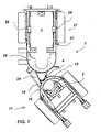
- la figure 2 est une vue de détail montrant l'articulation entre les deux parties du châssis.
- FIG. 1 is a top view of an articulated chassis of a road vehicle formed according to the invention and
- Figure 2 is a detail view showing the joint between the two parts of the chassis.
En référence aux dessins annexés, et plus particulièrement à la figure 1, la structure de châssis selon l'invention, désigné sous la référence générale (1), est composée d'une partie avant (11) et d'une partie arrière (21).With reference to the accompanying drawings, and more particularly to FIG. 1, the chassis structure according to the invention, designated under the general reference (1), is composed of a front part (11) and a rear part (21).
Les moyens d'aspiration (2) sont disposés sous la partie avant (11). La cuve de réception (3) des déchets aspirés est montée sur la partie arrière (21).The suction means (2) are arranged under the front part (11). The receiving tank (3) for aspirated waste is mounted on the rear part (21).
Les demi-châssis (11) et (21) sont chacun formés à partir d'un simple tube cintré en forme de U.The half-frames (11) and (21) are each formed from a simple tube curved in a U shape.
Les tubes (15, 25) sont disposés l'un en regard de l'autre, de telle manière que leurs parties coudées respectives soient face à face.The tubes (15, 25) are arranged opposite one another, in such a way their respective bent parts are face to face.
La partie ouverte de chaque tube en « U » est de ce fait dirigée vers l'extérieur, à savoir vers l'avant en ce qui concerne le tube (15) formant le demi-châssis avant et vers l'arrière pour le tube (25) qui constitue le demi-châssis arrière.The open part of each U-shaped tube is therefore directed towards the exterior, namely towards the front with respect to the tube (15) forming the front and rear half-frame for the tube (25) which constitutes the half-frame back.
Les tubes (15) et (25) formant les demi-châssis sont renforcés dans les zones soumise à des contraintes importantes, au moyen d'éléments de renfort en tôle (16) et (26) entourant les parties coudées desdits demi-tubes.The tubes (15) and (25) forming the half-frames are reinforced in areas subject to constraints important, by means of reinforcing sheet elements (16) and (26) surrounding the bent parts of said half-tubes.
L'articulation entre les demi-châssis (11) et (21) est réalisée au moyen de deux pièces en acier (14) et (24) soudées, respectivement sur les éléments en tôle (16) et (26) fixées sur les tubes (15) et (25). The articulation between the half-frames (11) and (21) is carried out by means of two steel parts (14) and (24) welded, respectively on the sheet metal elements (16) and (26) fixed on the tubes (15) and (25).
On pourra ainsi renforcer la structure du châssis sans pour autant en augmenter le poids dans des proportions de nature à compromettre sa maniabilité et son excellent rapport qualité-prix.We can thus strengthen the chassis structure without increase the weight in proportions likely to compromise his maneuverability and excellent value for money.
Les deux pièces soudées (14) et (24) sont reliées par une articulation à pivot (4).The two welded parts (14) and (24) are connected by a hinge to pivot (4).
De manière connue, divers flexibles (non représentés) relient les deux parties du châssis.In a known manner, various hoses (not shown) connect the two chassis parts.
De manière préférentielle, l'axe de l'articulation (4) sera interrompu dans sa partie médiane pour autoriser le passage des flexibles par le centre.Preferably, the axis of the joint (4) will be interrupted in its middle part to allow the passage of hoses through the center.
Ceci constitue un avantage important par rapport aux solutions connues. En effet, sur les châssis traditionnels, le passage des flexibles s'effectue sur les côtés, au dessus ou en dessous du point de rotation. Ceux-ci subissent de ce fait des contraintes beaucoup plus importantes, avec des risques élevés de rupture ou d'usure prématurée.This constitutes an important advantage compared to known solutions. Indeed, on traditional chassis, the passage of the hoses is carried out on the sides, above or below the point of rotation. These are therefore subject to much greater constraints, with high risk of rupture or premature wear.
La description qui précède permet d'apprécier la grande simplicité de la structure de châssis pour véhicule de voirie selon la présente invention.The above description makes it possible to appreciate the great simplicity of the chassis structure for road vehicle according to the present invention.
Chaque demi-châssis est réalisé à partir d'un nombre restreint d'éléments couramment disponibles, facilement usinables et de faible coût de revient.Each half-chassis is made from a limited number of elements commonly available, easily machinable and low cost.
La forme des tubes composant les demi-châssis, et leur disposition, sont parfaitement adaptées à la géométrie du véhicule et à ses déplacements.The shape of the tubes making up the half-frames, and their arrangement, are perfectly adapted to the geometry of the vehicle and its movements.
Bien entendu, la structure de châssis n'est pas limitée à la forme de réalisation décrite ci-dessus, et pourra recevoir toute variante sans que l'on sorte du cadre défini par les revendications.Of course, the frame structure is not limited to the shape of realization described above, and can receive any variant without that sort of the scope defined by the claims.
En particulier, les dimensions des tubes cintrés pourront varier.In particular, the dimensions of the bent tubes may vary.
Claims (2)
- Frame structure for utility vehicle comprising two half-frames (11, 21) articulated around a joint pin (4) and each formed using a bent tube (15, 25), the tubes (15,25) being arranged opposite one another so that their respective bent parts are face to face, characterised in that the tubes (15, 25) are U-shaped and have an open part which is directed outwards respectively from the front and rear ends of the vehicle and comprising sheet metal reinforcement elements (16, 26) surrounding said bent parts.
- Frame structure according to claim 1, characterised in that the joint pin (4) has an interruption in its centre to allow the flexible hoses linking the two half-frames (11, 21) to pass via the centre.
Applications Claiming Priority (2)
| Application Number | Priority Date | Filing Date | Title |
|---|---|---|---|
| FR9807136 | 1998-06-04 | ||
| FR9807136A FR2779402B1 (en) | 1998-06-04 | 1998-06-04 | CHASSIS STRUCTURE FOR ROAD VEHICLE |
Publications (2)
| Publication Number | Publication Date |
|---|---|
| EP0962380A1 EP0962380A1 (en) | 1999-12-08 |
| EP0962380B1 true EP0962380B1 (en) | 2003-05-21 |
Family
ID=9527095
Family Applications (1)
| Application Number | Title | Priority Date | Filing Date |
|---|---|---|---|
| EP19990440129 Expired - Lifetime EP0962380B1 (en) | 1998-06-04 | 1999-06-01 | Frame structure for utility vehicle |
Country Status (3)
| Country | Link |
|---|---|
| EP (1) | EP0962380B1 (en) |
| DE (1) | DE69908019T2 (en) |
| FR (1) | FR2779402B1 (en) |
Families Citing this family (5)
| Publication number | Priority date | Publication date | Assignee | Title |
|---|---|---|---|---|
| FR2842774B1 (en) * | 2002-07-29 | 2004-10-01 | Nicolas Jungo | ROAD VEHICLE |
| CN103963845B (en) * | 2014-04-25 | 2016-09-07 | 广州电力机车有限公司 | A kind of dumper frame |
| CN104085295B (en) * | 2014-07-03 | 2016-11-02 | 广州电力机车有限公司 | A kind of articulated truck dynamical system based on torque transmitter |
| CN104354768B (en) * | 2014-09-24 | 2017-02-01 | 北京林业大学 | Forestry underpan and hinge joint connection device thereof |
| CN109795558A (en) * | 2019-03-05 | 2019-05-24 | 航天重型工程装备有限公司 | A kind of pivotally connected frame and carrier |
Family Cites Families (2)
| Publication number | Priority date | Publication date | Assignee | Title |
|---|---|---|---|---|
| US3286781A (en) * | 1965-02-02 | 1966-11-22 | Fmc Corp | Articulated vehicle with pivotable frame steering |
| US5137106A (en) * | 1991-05-30 | 1992-08-11 | Ford New Holland, Inc. | Transmission control for articulated tractors |
-
1998
- 1998-06-04 FR FR9807136A patent/FR2779402B1/en not_active Expired - Fee Related
-
1999
- 1999-06-01 DE DE1999608019 patent/DE69908019T2/en not_active Expired - Fee Related
- 1999-06-01 EP EP19990440129 patent/EP0962380B1/en not_active Expired - Lifetime
Also Published As
| Publication number | Publication date |
|---|---|
| FR2779402B1 (en) | 2000-09-22 |
| DE69908019T2 (en) | 2003-12-11 |
| DE69908019D1 (en) | 2003-06-26 |
| EP0962380A1 (en) | 1999-12-08 |
| FR2779402A1 (en) | 1999-12-10 |
Similar Documents
| Publication | Publication Date | Title |
|---|---|---|
| FR2635130A1 (en) | ||
| FR2577862A1 (en) | CARRIER VEHICLE FOR LIFT, TRANSPORT AND DEVERSER, FOR EXAMPLE A CRASS POCKET | |
| FR2496566A1 (en) | AXLE, IN PARTICULAR REAR AXLE FOR TOURISM CARS COMPRISING GUIDE WHEELS INDEPENDENTLY ONE OF THE OTHER | |
| FR2916771A1 (en) | CONTROL APPARATUS FOR A WORKING VEHICLE | |
| EP0962380B1 (en) | Frame structure for utility vehicle | |
| FR2539092A1 (en) | MOTOR VEHICLE, IN PARTICULAR AGRICULTURAL UTILITY VEHICLE OF THE GENERATOR TRACTOR | |
| CA1049779A (en) | Draw bar for a motor grader | |
| CA1251039A (en) | Motor grader saddle | |
| FR2542686A1 (en) | INDEPENDENT SUSPENSION FOR MOTOR VEHICLE WHEEL | |
| EP1527911B1 (en) | Semi-deformable rear suspension with longitudinal flexibility | |
| EP0027397A1 (en) | Bearing frame for a mobile engine such as a hydraulic excavator | |
| FR2698825A1 (en) | Motor vehicle suspension - has hub carriers flexibly mounted on leading and trailing links with torsional cross member | |
| FR2836168A1 (en) | UTILITY VEHICLE COMPRISING A PIVOTING BASE ON A MOVEMENT DEVICE, WHICH HAS SMALL DIMENSIONS, IN PARTICULAR A BACKHOE | |
| FR2507131A1 (en) | RIGID AXLE SUSPENSION FOR MOTOR VEHICLE | |
| JP2012249537A (en) | Riding lawn mower | |
| FR2532671A1 (en) | Articulated combined loader and excavator jib | |
| FR2701627A1 (en) | Device which can be fitted to an automotive vehicle of the tractor type, especially for the upkeep of green spaces, banks and verges | |
| FR2526388A1 (en) | VEHICLE STEERING WHEELCHAIR, ESPECIALLY A PASSENGER CAR WITH A STEERING WHEEL AXLE | |
| FR2846931A1 (en) | LIGHT SITE VEHICLE, ESPECIALLY DUMP VEHICLE | |
| EP0683088B1 (en) | Front wheel suspension assembly with double transversal triangles and motor vehicle equipped with such an assembly | |
| FR2586989A1 (en) | STEERING ASSEMBLY FOR MOTOR VEHICLES | |
| FR2712137A3 (en) | Trailed mower | |
| FR2534110A1 (en) | DEVICE FOR SUPPORTING, AT LEAST PARTIALLY, THE WEIGHT OF AN AGRICULTURAL MACHINE | |
| EP0404627B1 (en) | Rear wheel suspension for motor vehicles | |
| FR2767507A1 (en) | Skid steer loader vehicle with front and rear ground propellers driven by transmissions for propelling and steering |
Legal Events
| Date | Code | Title | Description |
|---|---|---|---|
| PUAI | Public reference made under article 153(3) epc to a published international application that has entered the european phase |
Free format text: ORIGINAL CODE: 0009012 |
|
| AK | Designated contracting states |
Kind code of ref document: A1 Designated state(s): CH DE IT LI NL |
|
| AX | Request for extension of the european patent |
Free format text: AL;LT;LV;MK;RO;SI |
|
| AKX | Designation fees paid |
Free format text: CH DE IT LI NL |
|
| 17P | Request for examination filed |
Effective date: 20000609 |
|
| 17Q | First examination report despatched |
Effective date: 20020412 |
|
| RAP1 | Party data changed (applicant data changed or rights of an application transferred) |
Owner name: ALFRED KAERCHER GMBH & CO. |
|
| GRAH | Despatch of communication of intention to grant a patent |
Free format text: ORIGINAL CODE: EPIDOS IGRA |
|
| GRAH | Despatch of communication of intention to grant a patent |
Free format text: ORIGINAL CODE: EPIDOS IGRA |
|
| GRAA | (expected) grant |
Free format text: ORIGINAL CODE: 0009210 |
|
| RAP1 | Party data changed (applicant data changed or rights of an application transferred) |
Owner name: ALFRED KAERCHER GMBH & CO. KG |
|
| AK | Designated contracting states |
Designated state(s): CH DE IT LI NL |
|
| PG25 | Lapsed in a contracting state [announced via postgrant information from national office to epo] |
Ref country code: NL Free format text: LAPSE BECAUSE OF FAILURE TO SUBMIT A TRANSLATION OF THE DESCRIPTION OR TO PAY THE FEE WITHIN THE PRESCRIBED TIME-LIMIT Effective date: 20030521 |
|
| REG | Reference to a national code |
Ref country code: CH Ref legal event code: EP |
|
| REF | Corresponds to: |
Ref document number: 69908019 Country of ref document: DE Date of ref document: 20030626 Kind code of ref document: P |
|
| REG | Reference to a national code |
Ref country code: CH Ref legal event code: NV Representative=s name: LAURENT CROSSET-PERROTIN |
|
| NLV1 | Nl: lapsed or annulled due to failure to fulfill the requirements of art. 29p and 29m of the patents act | ||
| PLBE | No opposition filed within time limit |
Free format text: ORIGINAL CODE: 0009261 |
|
| STAA | Information on the status of an ep patent application or granted ep patent |
Free format text: STATUS: NO OPPOSITION FILED WITHIN TIME LIMIT |
|
| 26N | No opposition filed |
Effective date: 20040224 |
|
| PGFP | Annual fee paid to national office [announced via postgrant information from national office to epo] |
Ref country code: IT Payment date: 20090624 Year of fee payment: 11 |
|
| PGFP | Annual fee paid to national office [announced via postgrant information from national office to epo] |
Ref country code: DE Payment date: 20090609 Year of fee payment: 11 Ref country code: CH Payment date: 20090918 Year of fee payment: 11 |
|
| REG | Reference to a national code |
Ref country code: CH Ref legal event code: PL |
|
| PG25 | Lapsed in a contracting state [announced via postgrant information from national office to epo] |
Ref country code: IT Free format text: LAPSE BECAUSE OF NON-PAYMENT OF DUE FEES Effective date: 20100601 |
|
| PG25 | Lapsed in a contracting state [announced via postgrant information from national office to epo] |
Ref country code: CH Free format text: LAPSE BECAUSE OF NON-PAYMENT OF DUE FEES Effective date: 20100630 Ref country code: LI Free format text: LAPSE BECAUSE OF NON-PAYMENT OF DUE FEES Effective date: 20100630 Ref country code: DE Free format text: LAPSE BECAUSE OF NON-PAYMENT OF DUE FEES Effective date: 20110101 |