EP0962012B1 - Schutzabdeckung zur verwendung mit einem saiteninstrument - Google Patents
Schutzabdeckung zur verwendung mit einem saiteninstrument Download PDFInfo
- Publication number
- EP0962012B1 EP0962012B1 EP98914856A EP98914856A EP0962012B1 EP 0962012 B1 EP0962012 B1 EP 0962012B1 EP 98914856 A EP98914856 A EP 98914856A EP 98914856 A EP98914856 A EP 98914856A EP 0962012 B1 EP0962012 B1 EP 0962012B1
- Authority
- EP
- European Patent Office
- Prior art keywords
- shield body
- instrument
- strings
- protective cover
- front side
- Prior art date
- Legal status (The legal status is an assumption and is not a legal conclusion. Google has not performed a legal analysis and makes no representation as to the accuracy of the status listed.)
- Expired - Lifetime
Links
Images


Classifications
-
- G—PHYSICS
- G10—MUSICAL INSTRUMENTS; ACOUSTICS
- G10G—REPRESENTATION OF MUSIC; RECORDING MUSIC IN NOTATION FORM; ACCESSORIES FOR MUSIC OR MUSICAL INSTRUMENTS NOT OTHERWISE PROVIDED FOR, e.g. SUPPORTS
- G10G7/00—Other auxiliary devices or accessories, e.g. conductors' batons or separate holders for resin or strings
Definitions
- the present invention relates in general to a protective cover for use with a stringed musical instrument, the latter having an instrument body, a neck and impact- and shock-sensitive parts located on said instrument body and the neck, said sensitive parts being at least formed by the strings and by a bridge supporting the strings.
- Such sensitive parts also can be e.g. piezo-electric pickups, magnetic pickups and tremolos of acoustic or electric guitars.
- the German patent No. 58857 shows a textile strip which can be installed to cover the strings of a violin along the finger board area.
- This textile strip does not protect the bridge when the violin is put into or taken out of an instrument case, nor does it protect the bridge during transportation of the violin when the case and the violin in it are subject to impacts, shocks or vibrations.
- the bridge exceeds the level of the front side and is sometimes fastened to the front side of the instrument only by the tension of the strings, the bridge can be subject to physical attacks and damages during transport.
- a protective cover for the strings of a musical instrument is known from US-A-4121494.
- This cover comprises a clip shaped shield, whereby the shield has such a length as to cover the strings along the length of the span, i.e. the distance between the bridge and the nut of the musical instrument, e.g. an acoustic guitar.
- the shield is inserted over the strings through an open mouth along a longitudinal side edge of the shield.
- This clip shaped shield gives protection against mechanical stress during transportation to the strings only.
- the bridge which projects from the front side of the instrument body is still exposed to mechanical stress and damages during transportation.
- Another object of the invention is to provide an improved protective cover that can be equipped with a protecting shelter space to store and transport the highly sensitive bows of the violin family, i.e. of violins, violas, violincelli and double basses.
- a further object of the invention is to provide an improved protective cover for use with stringed musical instruments that have sensitive parts not only in the form of strings and bridges but also in the form of piezo-electric pickups, magnetic pick ups, preamplifiers, or tremolos, i.e. for use with acoustic and electric guitars.
- the present invention relates to a protective cover for use with a stringed musical instrument, the latter having an instrument body, a neck, and impact- and shock-sensitive parts located on said instrument body and said neck, said sensitive parts being at least formed by the strings and by a bridge supporting said strings at a string supporting line at the front side of the instrument body, said string-supporting line forming the highest line of elevation relative to the front side of the instrument body as compared to the adjacent portions of the strings, said strings and said bridge defining a substantially rectangled zone within the front side area of the instrument body, the instrument body having an upper edge area adjacent said neck, a lower edge area opposite its upper edge area and instrument recesses and projections located adjacent to each other within the area of the front side of the instrument body.
- the protective cover comprises a roof-like shaped shield body adapted to cover said substantially rectangled zone.
- the shield body has a roof portion with a substantially convex contour on the top side thereof, a substantially concave contour on its bottom side, and an inner string channel open to the bottom side.
- Said inner string channel forms a housing space for the strings and the bridge, when the shield body is mounted, and is defined on ist upper side by an inner wall of said roof portion.
- Lateral wall portions of the shield body have opposed lateral flanks and define said inner string channel by both of its lateral flanks.
- the inner wall of the roof portion and the lateral wall portions of the inner string channel accomodate the strings as to their ascending and descending course, respectively.
- Fixing projections are arranged at the neck-side end and at the lower end of the shield body adapted to engage the upper and lower edge areas of the instrument body, respectively, and thereby fix the shield body, when mounted on the front side of the instrument body, against longitudinal movement.
- the protective cover furthermore comprises locking means for locking the shield body in its mounted position.
- locking projections projecting from the lateral wall portions of the shield body, suitable to engage the instrument projections.
- the shield body is made of elastically deformable material to permit squeezing the bottom side of the shield body onto the front side of the instrument body when applying substantially vertical directed forces upon the roof portion, thereby permitting a sliding motion of said locking projections from a premounting position into said mounted position, according to which the locking projections grip under the instrument projections, as well as having moved the fixing projections into their fixing position to engage the upper and the lower edge areas of the instrument body when simultaneously applying a longitudinally directed displacement force upon the shield body.
- a window opening is provided within the roof portion of the shield body adjacent the apex area and at a side therof which faces the neck-side end.
- the window opening is adapted to observe therethrough the position of the locking projections which they assume in said premounting and mounted positions of the shield body and to form a handle in cooperation with the adjacent portion of the apex area and the roof portion.
- the shield body at least at one longitudinally extending side of its roof portion has an adherent trough-like base extending from the neck-side end to the lower end of the shield body, this base having a groove to embed an instrument bow therein.
- the groove of the trough-like base has resilient walls adapted to fix said embedded instrument bow by elastic deformation. It is also preferred, that at each of thelongitudinally extending sides of the roof portion there is provided an adherent trough-like base and that each of the two bases have a groove to accomodate one instrument bow, respectively.
- the sensitive parts especially the strings and the bridge
- a violoncello a double bass, a viola, or a violin.
- the shield body With slight alterations of the shield body it is possible to match the special needs of protection in respect to acoustic guitars (with and without piezoelectric pickups) and to electric or solid body guitars having in addition to their strings and bridges piezoelectric and/or magnetic pickups and tremolos.
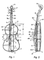
- a cello C representing an example for a stringed musical instrument to be protected.
- the cello C has an instrument body 1, a neck 7, and impact- and shock-sensitive parts located on the instrument body 1 and the neck 7.
- Said sensitive parts are formed by the strings 2 and by a bridge 5 supporting strings 2 at string supporting line a10 at the front side of the instrument body 1.
- the string-supporting line a10 forms the highest line of elevation relative to the front side 1.1 of the instrument body 1 as compared to the adjacent portions of the strings 2.
- the strings 2 and the bridge 5 define a substantially rectangled zone a2 within the front side area of the instrument body 1.
- the instrument body 1 has an upper edge area a3 adjacent the neck 7, a lower edge area a4 opposite its upper edge area a3 and instrument recesses a5 and projections 9, 9' located adjacent to each other within the area of the front side 1 'of the instrument body 1 and hereinafter referred to finger board 9 and interface 9' of finger board 9, respectively.
- the strings comprise a string combination of four strings, namely 2c, 2g, 2d and 2a, which is installed on the instrument body 1.
- the strings 2 are fixed at one end to the tailpiece 3 and extend over the bridge 5 to the threads 8 of the pegs 6, to which the other ends of the strings 2 are tensionably fixed.
- the tailpiece 3 is anchored at the endbutton 4 and rests with its foot on the lower edge a4 of the instrument body 1.
- Below of and spaced to the strings 2 as well as spaced to the front side 1.1 there extends the finger board 9 from the neck 7 along a first distance a6 almost to the middle of the front side 1.1 of the instrument body 1, terminating with a second distance a1 with respect to the bridge 5.
- the strings 2 extend from the tailpiece 3 ascending, i.e. with increasing vertical distance with respect to the front side 1.1, reaching their point of culmination at the supporting line a10 of the bridge 5 and then descending, i.e. with decreasing vertical distance with respect to the front side 1.1, following the finger board 9 up to the threads 8 of the pegs 6, the latter being located between the end of the neck 7 and the scroll 10.
- the fixing of the bridge 5 standing up vertically from the front side 1.1 is secured solely by the tension of the strings 2 tightened from the tailpiece (3) to the pegs (6). This renders the sensitive parts 5 and 2 and the area around the bridge 5 extremely injurable by even the slightest physical violence, especially during transportation, as the effect of any such violence results unavoidably in hitting the bridge 5, its foot portion and the surrounding area.
- the instrument body is shielded against the aforementioned effects of any occuring physical violence guiding the impacts and shock forces to the stable upper and lower edge areas of the the instrument body 1.
- the protective cover comprises a roof-like shaped shield body 11 that is, according to Figs. 1 to 7 superimposed or put over the rectangled zone a2 of the front side 1.1 of the instrument body 1 where the sensitive parts 5,2 are located, and is secured thereto preferably by form-locking.
- the roof-like shaped shield body 11 (hereinafter briefly called shield body) is adapted to cover the substantially rectangled zone a2 (Fig. 1) and has a top side b1, a bottom side b2, a neck-side end 16' and a lower end 15' opposite said neck-side end 16' (see Figs. 3 to 5).
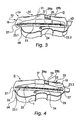
- the shield body 11 furthermore has a roof portion 19 with a substantially convex contour on the top side b1 thereof, a substantially concave contour b3 on its bottom side b2 as can be seen in Fig. 5 when one compares the straight dottet line b3' with the contour line b3, and an inner string channel 12 open to said bottom side b2.
- the inner string channel 12 forms a housing space for the strings 2 and the bridge 5, when the shield body 11 is mounted (see mounted position II in Fig. 4) and is defined on its upper side by an inner wall b19 of the roof portion 19.
- the lateral wall portions 13, 14 of the shield body 11 have opposed lateral flanks b13, b14 (Fig. 5) and define the inner string channel 12 by both of its lateral flanks b13, b14 and by its bottom sides b2, b2 that also represent the bottom side of the shield body 11 and hence are concavely contoured or arched (b3).
- the inner wall b19 of the roof portion 19 and the lateral wall portions 13, 14 of the inner string channel 12 accomodate the strings 2 as to their ascending and descending course, respectively.
- First fixing projections 16.1, 16.2 are arranged at the neck-side end 16' of the shield body 11 and a second fixing projection 15 is provided at the lower end 15' of the shield body 11, adapted to engage said upper and lower edge areas a3, a4 of the instrument body 1, respectively,(compare Fig. 2) and thereby fix the shield body 11, when mounted on the front side 11 of the instrument body 1, against longitudinal movement (see mounted position II in Figs 1,2, and 4).
- the fixing projections 16.1, 16.2 and 15 are formed as angled jaws designed to grip over the upper and lower edge areas a3, a4 of the instrument body 11.
- the fixing projection 15 is in one piece whereas there are two fixing projections 16.1, 16.2 with an intermediate space b16 in between to accomodate the adjacent portion of the neck 7.
- the locking means for locking the shield body 11 in its mounted position II comprise locking projections 20, 21 (see Fig. 5) projecting from the lateral wall portions 13, 14 into a portion of the inner string chanel 12.
- the locking projections 20,21 are designed to engage the instrument projections 9,9', i.e. the interface 9' and the adjacent portions of the finger board 9.
- the locking means further comprises an elastic deformability of the shield body 11 in order to have squeezed the bottom side b2 of the shield body 11 onto the front side 1.1 of the instrument body 1 when applying substantially vertical directed forces F1 on the roof portion 19, as is depicted by dotted lines in Fig.
- the shield body 11 is made of elastically deformable plastic material.
- a favored plastic material in this connection is extruded polypropylen (EPP).
- EPP extruded polypropylen
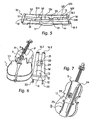
- the shield body 11 has an apex area 17 surrounding and accomodating with its inner space the bridge 5 and portions of the strings 2 neighboring the bridge 5.
- the roof portion 19 and the lateral wall portions 13, 14 are tapered along the distance between the apex area 17 and the neck-side end 16' as well as the lower end 15', respectively, of the shield body 11. It is advantageous to provide a window opening 29 within the roof portion 19 of the shield body 11 and adjacent the apex area 17 at one side therof which faces the neck-side end 16'.
- the window opening 29 is adapted to observe therethrough the locking projections 20, 21 in the premounting and mounted positions Ia, II of the shield body 11 and to form handles by the edges 29a, 29b of the window opening 29, i.e. together with the adjacent portions of the apex area 17 and the roof portion 19 (see Figs. 3 and 4).
- the arched construction of the shield body guarantees a complete relieving of the front side 1.1 of the cello C from the effects of physical loads possibly attacking the area around the bridge 5 of the instrument C.
- the construction and the use of elastically deformable material offers the possibility of transferring the effects of physical loads to the resting points (15, 16.1, 16.2) at the edges a3, a4 of the instrument similar to putting a shell constructed bridge on its. pylons.
- the shield body 11 is constructed in a way to protect the complete vulnerable portions on the front side 1.1 along the strings 2.
- Fig. 5 shows the inner string channel 12 in an upside down position of the shield body 11.
- the inner string channel 12 follows the ascending and descending course of the strings 2 all the way from the tailpiece 3 over the bridge 5 down to the upper edge area a3 of the front side 1.1 of the instrument body 1. Due to the shell construction of the shield body 11 the lateral wall portions 13, 14 (acting as protective flanks) on both sides of the inner string channel 12 form an elastical balance along the front side 1.1, resting only with their neck-side and lower ends 16', 15' and jaw-like -projections 15, 16.1, 16.2 on the upper and lower edge areas a3, a4 of the front side 1.1 and the instrument body 1.
- the height of the locking projections 20, 21 projecting from the lateral wall portions 13, 14 or lateral flanks b13, b14 corresponds exactly to the vertical distance between the lower end of the fingerboard 9 and the front side 1.1.
- the distance between the locking projections 20, 21 below the window opening 29 corresponds exactly to the cross dimension of the string combination 2 which is slightly shorter than the width of the lower end of the fingerboard 9. Due to this fact the shield body 11 can easily be lowered vertically onto the instrument body 1 letting the string combination pass between the locking projections 20, 21 within the area of the gap al.. When pushing the shield body 11 towards the upper edge area a3 the instrument body 1 - see movement of the shield body 11 in Figs. 3 and 4 - the locking projections 20, 21 slip under the fingerboard (9) creating a firmly secured unit of the instrument bodyl and the shield body 11.
- the fixing projections 15, 16.1, 16.2 softly clickshut with the edge areas a3, a4.
- the distance between the neck-side end and the lower end 16', 15' of the shield body corresponds exactly to the dimension of the front side 1.1 of the instrument body 1.
- the shield body 11 is firmly fixed onto both ends of the instrument body 1, and along the front side 1. 1 it is held firmly by the locking projections 20,21 under the fingerboard 9.
- the shield body 11 In the fixed position II (see Fig. 4) the shield body 11 rests on three points of the instrument body 1: The upper and lower edge areas a3, a4, and by the locking projections 20, 21 it is fixed under the stable fingerboard 9, thus obtaining a maximum protection of the front side 1.1 which - except for the upper and lower edge areas a3, a4 - is not being touched at all by the elastic shield body, thereby granting very good damping characteristics to the protective cover including the shield body. Since the shield body 11 in its mounted position II is elastically pretensioned, it cannot be loosened unintentionally. In order to demount the shield body one has to perform the described locking actions in a reverse sequence, i.e. unlocking the fixing projections 16.1,16.2, when applying the pressing force F1 (Fig. 3) and simultaneously applying a longitudinal force opposed to the force F2.
- the shield body 11 at least at one longitudinally extending side of its roof portion 19, preferably on both of said sides, has an adherent trough-like base 24, 25 extending from the neck-side end 16' to its lower end 15'of said shield body.
- Each of these bases 24, 25 have a groove 27 within the area of base enforcements 26 to embed an instrument bow 22, 23 therein, i.e. tip and frog 23.1, 23.2, thereof.
- the grooves of the trough-like bases have resilient walls adapted to fix the embedded instrument bows by elastic deformation or snap action(see Figs. 1 to 4). Hence the bows are safely stored on the shield body 11 and fully protected against physical loads during transportation.
- the bows 22, 23 are depicted schematically by black fat lines.
- Fig. 8 shows the opened bag 30 having a enlarged projecting or convex portion 31 on ist front side, said portion 31 accomodating the form and the volume of the shield body 11.
- Fig. 9 shows the bag 30 having the cello C together with the attached shield body 11 in its inside. Therefor the cavity of the portion 31 is filled by the shield body, and the portion projects in the form of an elevation or bulb.
- the protective cover comprising the shield body 11 is not only applicable to the cello C shown, but also to double basses, violas, or violins, - e.g. to the violin family, all of those instruments having exposed bridges an strings supported by the bridges.
- the size of the shield body has to be adapted to the size of the stringed musical instrument to be protected.
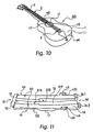
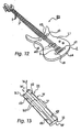
- the shield body can be used - with slight alterations - with an acoustic guitar (Figs. 10 and 11) and with an electric or solid body guitar (Figs. 12 and 13).
- Fig. 10 shows an acoustic guitar AG with a usually circular sound aperture c1 overlying the strings 2 on both sides thereof. Thereby segmental partial openings c2 are accessible from above.
- the locking projections c3 and c4 of the shield body 110 (which is depicted in an enlarged scale as compared to the guitar AG of Fig. 10) are adapted to fit into the segmental partial openings c2, c1, respectively, when the shield body 110 is put into a premounting position.
- the locking projections c3 and c4 have recesses c31, c41, respectively, so that they can be moved to grip under the front side wall 1.1 adjacent the rim of the sound aperture when applying the vertically and longitundinally directed forces (see arrows F1 and F2 in Fig. 3) upon the shield body 110.
- the locking means for locking the shield body in its mounted position here comprises a first adhesive lining d1 located and fixed at a first spot areas on the front side 1.1 of the instrument body 1 within the area covered by the shield body 111 of Fig. 13 in its mounted position.
- the locking means comprises, therefore, a second adhesive lining d2 located and fixed at second spot areas on the bottom side b2 of the shield body 111.
- the first and said second spot areas coincide and stick together with their adhesive linings d1, d2 when the shield body 111 is in its mounted position.
- the first and said second adhesive linings d1, d2 preferably are formed by ferromagnetic armature inserts and corresponding permanent magnet inserts, respectively (not shown in detail). It is also preferred, that the shield bodies 110 and 111 of Figs. 11 and 13 have the concave or arched bottom side configuration as described with respect to the first embodiment. This facilitates the mounting and gives better protection to the sensitive parts - (bridges 5, strings 2, magnetic pickups d3 (Fig. 12) or a piezoelectric pickup integrated in the bridge of guitar AG (Fig. 10) - .Together with the arched bottom side configuration, the mounted position of the embodiment of Figs. 12, 13 is reached also when applying the forces F1 and F2 (Fig. 3) upon the shield body 111, the armatures d1 and the permanent magnets d2 snapping and sticking together at the end of this mounting procedure.
- the construction of the shield bodies 110, 111 is similar to the one of the shield body 11 (first embodiment); insofar the same reference numerals apply.
Landscapes
- Physics & Mathematics (AREA)
- Engineering & Computer Science (AREA)
- Acoustics & Sound (AREA)
- Multimedia (AREA)
- Stringed Musical Instruments (AREA)
Claims (18)
- Schutzkörper für ein Saiteninstrument (C; AG) mit Korpus (1), Hals (7) und an Korpus (1) und Hals (7) sich befindenden stoß- und schlagempfindlichen Instrumententeilen, welch letztere zumindest gebildet sind von den Saiten (2) und dem Saitensteg (5), mit folgenden Merkmalen des Saiteninstrumentes: der Saitensteg (5) unterstützt die Saiten (2) längs einer Saitenstützlinie (a10) auf der Frontseite (1.1) des Korpus (1); die Saitenstützlinie (a10) bildet die höchste Erhebung auf der Korpus-Frontseite (1.1) im Vergleich zu den angrenzenden Abschnitten der Saiten (2); die Saiten und der Saitensteg definieren eine im wesentlichen rechteckige Zone (a2) innerhalb der Frontseite (1.1) des Korpus (1); der Korpus (1) hat einen oberen Kantenbereich (a3) angrenzend an den Hals (7), einen unteren Kantenbereich (a4) gegenüberliegend seinem oberen Kantenbereich (a3) sowie Instrumenten-Rücksprünge (a5) und -Vorsprünge (9, 9'), welche benachbart zueinander innerhalb der Korpus-Frontseite (1.1) angeordnet sind, gekennzeichnet durch die folgenden Merkmale:der Schutzkörper (11) ist dachartig und so geformt, daß er die im wesentlichen rechteckige Zone (a2) überdeckt; er hat eine Oberseite (b1), eine Unterseite (b2), ein halsseitiges Ende (16') und ein dem halsseitigen Ende (16') gegenüberliegendes unteres Ende (15'); der Schutzkörper (11) hat ferner eine Dachpartie (19) mit einer im wesentlichen konvexen Kontur an deren Oberseite (b1), eine im wesentlichen konkave Kontur (b3) an deren Unterseite (b2) und einen inneren Saiten-Durchgangskanal (12), welcher zur Unterseite hin offen ist;der Saiten-Durchgangskanal (12) bildet in seinem montierten Zustand einen Aufnahmeraum für die Saiten (2) und den Saitensteg (5) und ist an seiner Oberseite begrenzt durch eine Innenwand der Dachpartie (19);Seitenwandpartien (13, 14) des Schutzkörpers (11) weisen einander gegenüberliegende Flanken (b13, b14) auf, welche den Saiten-Durchgangskanal (12) seitlich begrenzen; beide Seitenwandpartien (13, 14) haben je eine konkave Bodenfläche, die beide die konkave Kontur (b3) an der Unterseite (b2) des Schutzkörpers (11) bilden; die Innenwand der Dachpartie (19) und die Seitenwandpartien (13, 14) des Saiten-Durchgangskanals (12) sind an den ansteigenden bzw. abfallenden Verlauf der Saiten (2) angepaßt;Haltevorsprünge (16.1, 16.2; 15) am halsseitigen Ende (16') und am unteren Ende (15') des Schutzkörpers (11) sind dazu vorgesehen, am oberen und unteren Kantenbereich (a3, a4) des Korpus (1) jeweils anzugreifen und dadurch den Schutzkörper (11), wenn dieser an der Frontseite (1.1) des Korpus (1) montiert ist, gegen Längsverschiebung zu fixieren,Verriegelungsmittel zum Verriegeln des Schutzkörpers (11) in seiner montierten Position (II), bestehend aus Verriegelungs-Vorsprüngen (20, 21), welche von den Seitenwandpartien (13, 14) hervorstehen und so ausgebildet sind, daß sie mit den Instrumenten-Vorsprüngen (9, 9') in Eingriff bringbar sind; der Schutzkörper (11) besteht dabei aus elastisch deformierbarem Material, so daß die Unterseite (b2) des Schutzkörpers (11) gegen die Frontseite (1.1) des Korpus (1) gedrückt werden kann, wenn im wesentlichen vertikal gerichtete Kräfte (F1) auf die Dachpartie (19) ausgeübt werden, wodurch eine Gleitbewegung der Verriegelungs-Vorsprünge (20, 21) aus einer Vor-Montageposition (Ia) in die montierte Position (II) ermöglicht wird, gemäß welcher sowohl die Verriegelungs-Vorsprünge (20, 21) unter die Instrumenten-Vorsprünge (9, 9') greifen als auch die Haltevorsprünge (16.1, 16.2; 15) in ihre Halteposition, übergreifend die oberen und unteren Kantenbereiche (a3, a4) des Korpus (1), bewegbar sind, wenn gleichzeitig eine längsgerichtete Verlagerungskraft (F2) auf den Schutzkörper (11) ausgeübt wird.
- Schutzkörper nach Anspruch 1, dadurch gekennzeichnet, daß er mit einem erhöhten Scheitelbereich (17) den Saitensteg (5) und die diesem benachbarten Saiten (2) umgibt, wobei die Dachpartie (19) und die Seitenwandpartien (13, 14) vom Scheitelbereich (17) bis zum halsseitigen Ende (16') zum einen und bis zum unteren Ende (15') zum anderen sich verjüngen.
- Schutzkörper nach Anspruch 1, dadurch gekennzeichnet, daß das Saiteninstrument (C) mit einem am Hals (7) befestigten Griffbrett (9) sich längs einer ersten Distanz (a6) in die im wesentlichen rechteckige Zone (a2) erstreckt, und zwar unterhalb der und beabstandet zu den Saiten (2) und oberhalb der und beabstandet zur Frontseite (1.1) des Korpus (1); dabei wird die erste Distanz (a6) begrenzt durch die Endfläche (9') des freien Endes des Griffbrettes (9), welche vom Saitensteg (5) beabstandet ist durch eine zweite Distanz (a1); das freie Ende des Griffbrettes (9) bildet die-erwähnten Instrumenten-Vorsprünge (9. 9'), wobei die Verriegelungs-Vorsprünge (20, 21) sich innerhalb der zweiten Distanz (a1) sich befinden, wenn der Schutzkörper (11) seine Vor-Montageposition (Ia) einnimmt, so daß die Gleitbewegung der Verriegelungs-Vorsprünge (20, 21) letztere veranlaßt, unter das freie Ende des Griffbrettes (9) zu greifen.
- Schutzkörper nach Anspruch 2, dadurch gekennzeichnet, daß eine Fensteröffnung (29) innerhalb seiner Dachpartie (19) und benachbart zum Scheitelbereich (17) auf einer dem halsseitigen Ende (16') zugewandten Seite des Scheitelbereiches (17) angeordnet ist, wobei die Fensteröffnung (29) zur Beobachtung der Verriegelungs-Vorsprünge (20, 21) in der Vo-Montageposition und der montierten Position (Ia, II) des Schutzkörpers (11) und zur Bildung eines Griffes dient, zu welchem die angrenzenden Teile des Scheitelbereiches (17) und der Dachpartie (19) gehören.
- Schutzkörper nach Anspruch 1, dadurch gekennzeichnet, daß er an die Größe eines Violincellos angepaßt ist.
- Schutzkörper nach Anspruch 1, dadurch gekennzeichnet, daß er an die Größe eines Kontrabasses angepaßt ist.
- Schutzkörper nach Anspruch 1, dadurch gekennzeichnet, daß das Saiteninstrument eine akustische Gitarre (AG) ist, welche in der frontseitigen Wand (1.1) ihres Korpus (1) ein im wesentlichen kreisförmiges Schallloch (c1) unterhalb der Saiten (2) und dazu benachbarte Wandpartien aufweist; dabei hat das Schallloch (c1) beidseits der Saiten (2) einen Überstand in Gestalt kreissegmentförmiger Öffnungen (c2), welche die besagten Instrumenten-Vorsprünge und -Rücksprünge bilden, wobei Verriegelungs-Vorsprünge (c3, c4) des Schutzkörpers (11) so geformt sind, daß sie in die kreissegmentförmigen Öffnungen (c2) einfügbar sind, wenn der Schutzkörper (11) sich in seiner Vor-Montageposition (Ia) befindet, und unter die besagten Instrumenten-Vorsprünge greifen, wenn der Schutzkörper (11) in seine montierte Position (II) geschoben ist.
- Schutzkörper nach Anspruch 1, dadurch gekennzeichnet, daß er zumindest an einer Längsseite seiner Dachpartie (19) eine trogartige Anformung (24, 25) hat, welche sich vom halsseitigen Ende (16') bis zum unteren Ende (15') des Schutzkörpers (11) erstreckt und eine Vertiefung (27) zum Einfügen eines Instrumentenbogens (22, 23) aufweist.
- Schutzkörper nach Anspruch 8, dadurch gekennzeichnet, daß die Vertiefung (27) der trogartigen Anformung (24, 25) mit elastischen Wänden ausgestattet ist, so daß der eingefügte Instrumentenbogen (22, 23) mittels elastischer Deformation gehaltert wird.
- Schutzkörper nach Anspruch 8, dadurch gekennzeichnet, daß an beiden Längsseiten der Dachpartie (19) je eine trogartige Anformung (24, 25) mit je einer Vertiefung (27) zur Aufnahme je eines Instrumentenbogens (22, 23) vorgesehen ist.
- Schutzkörper nach Anspruch 1, dadurch gekennzeichnet, daß er aus elastisch deformierbarem Kunststoff besteht.
- Schutzkörper nach Anspruch 11, dadurch gekennzeichnet, daß der Kunststoff aus extrudiertem Polypropylen (EPP) besteht.
- Schutzkörpers für Elektrogitarren (EG) mit Korpus (1), Hals (7) und an Korpus (1) und Hals (7) sich befindenden stoß- und schlagempfindlichen Instrumententeilen, welch letztere zumindest gebildet sind von den Saiten (2) und dem Saitensteg (5), mit folgenden Merkmalen des Saiteninstrumentes: der Saitensteg (5) unterstützt die Saiten (2) längs einer Saitenstützlinie (a10) auf der Frontseite (1.1) des Korpus (1); die Saitenstützlinie (a10) bildet die höchste Erhebung auf der Korpus-Frontseite (1.1) im Vergleich zu den angrenzenden Abschnitten der Saiten (2); die Saiten und der Saitensteg definieren eine im wesentlichen rechteckige Zone (a2) innerhalb der Frontseite (1.1) des Korpus (1); der Korpus (1) hat einen oberen Kantenbereich (a3) angrenzend an den Hals (7), einen unteren Kantenbereich (a4) gegenüberliegend seinem oberen Kantenbereich (a3), gekennzeichnet durch die folgenden Merkmale:der Schutzkörper (111) ist dachartig und so geformt, daß er die im wesentlichen rechtekkige Zone (a2) überdeckt; er hat eine Oberseite (b1), eine Unterseite (b2), ein halsseitiges Ende (16') und ein dem halsseitigen Ende (16') gegenüberliegendes unteres Ende (15'); der Schutzkörper (111) hat ferner eine Dachpartie (19) mit einer im wesentlichen konvexen Kontur an deren Oberseite und einen inneren Saiten-Durchgangskanal (12), welcher zur Unterseite hin offen ist;der Saiten-Durchgangskanal (12) bildet in seinem montierten Zustand einen Aufnahmeraum für die Saiten (2) und den Saitensteg (5) und ist an seiner Oberseite begrenzt durch eine Innenwand der Dachpartie (19);Seitenwandpartien (13, 14) des Schutzkörpers (11) weisen einander gegenüberliegende Flanken (b13, b14) auf, welche den Saiten-Durchgangskanal (12) seitlich begrenzen; beide Seitenwandpartien (13, 14) haben je eine Bodenfläche; die-Innenwand der Dachpartie (19) und die Seitenwandpartien (13, 14) des Saiten-Durchgangskanals (12) sind an den ansteigenden bzw. abfallenden Verlauf der Saiten (2) angepaßt;Haltevorsprünge (16.1, 16.2; 15) am halsseitigen Ende (16') und am unteren Ende (15') des Schutzkörpers (111) sind dazu vorgesehen, am oberen und unteren Kantenbereich (a3, a4) des Korpus (1) jeweils anzugreifen und dadurch den Schutzkörper (111), wenn dieser an der Frontseite (1.1) des Korpus (1) montiert ist, gegen Längsverschiebung zu fixieren,Verriegelungsmittel zum Verriegeln des Schutzkörpers (111) in seiner montierten Position (II), umfassend einen ersten Haft-Belag (d1), positioniert und befestigt an ersten Stellen der Frontseite (1.1) des Korpus (1) innerhalb des Flächenbereiches, der vom Schutzkörper (111) in seiner montierten Position (II) überdeckt wird, und umfassend einen zweiten Haft-Belag (d2), poisitioniert und befestigt an zweiten Stellen auf der Unterseite (b2) des Schutzkörpers (111), wobei die ersten und zweiten Stellen in der montierten Position (II) des Schutzkörpers (111) sich überdecken und zusammenhaften.
- Schutzkörper nach Anspruch 13, dadurch gekennzeichnet, daß der erste bzw. zweite Haftbelag (d1, d2) der Verriegelungsmittel gebildet sind durch ferromagnetische Anker-Einsätze bzw. durch zugehörige permanentmagnetische Einsätze.
- Schutzkörper nach Anspruch 13, dadurch gekennzeichnet, daß die Unterseiten (b2) der Seitenwandpartien (13, 14) des Schutzkörpers (111) eine konkave Kontur aufweisen und der zweite Haftbelag (d2) an der Unterseite (b2) der Seitenwandpartien (13, 14) befestigt ist, daß der Schutzkörper (111) aus elastisch deformierbarem Material besteht und zu Einnahme einer Vor-Montageposition (Ia) ausgebildet ist, in welcher die ersten und zweiten Haftbeläge (d1, d2) voneinander beabstandet sind und so einen Spalt bilden, daß die ersten und zweiten Haftbeläge (d1, d2) miteinander in Kontakt gelangen und aneinander haften, wenn der Schutzkörper (111) durch Ausüben einer im wesentlichen vertikalen Kraft (F1) auf seine Dachpartie (19) verformt wird, so daß der Spalt geschlossen und die montierte Position (II) vom Schutzkörpers (111) eingenommen wird.
- Schutzkörper nach Anspruch 13, dadurch gekennzeichnet, daß die ferromagnetischen Anker-Einsätze (d1) auf der Frontseite des Korpus (1) innerhalb der im wesentlichen rechteckigen Zone und die permanentmagnetischen Einsätze (d2) auf der Unterseite (b2) der Seitenwandpartien (13, 14) des Schutzkörpers (111) installiert sind.
- Schutzkörper nach Anspruch 1, dadurch gekennzeichnet, daß der Schutzkörper (11) an die Größe einer Viola angepaßt ist.
- Schutzkörper nach Anspruch 1, dadurch gekennzeichnet, daß der Schutzkörper (11) an die Größe einer Violine angepaßt ist.
Applications Claiming Priority (3)
| Application Number | Priority Date | Filing Date | Title |
|---|---|---|---|
| DE19707688A DE19707688A1 (de) | 1997-02-26 | 1997-02-26 | Schutzkörper für ein Saiteninstrument zum Schutz empfindlicher Instrumententeile beim Einfügen in ein und Herausnehmen aus einem Transportbehältnis und beim Transport in letzterem |
| DE19707688 | 1997-02-26 | ||
| PCT/EP1998/001079 WO1998038629A1 (en) | 1997-02-26 | 1998-02-26 | Protective cover for use with a stringed musical instrument |
Publications (2)
| Publication Number | Publication Date |
|---|---|
| EP0962012A1 EP0962012A1 (de) | 1999-12-08 |
| EP0962012B1 true EP0962012B1 (de) | 2002-04-17 |
Family
ID=7821544
Family Applications (1)
| Application Number | Title | Priority Date | Filing Date |
|---|---|---|---|
| EP98914856A Expired - Lifetime EP0962012B1 (de) | 1997-02-26 | 1998-02-26 | Schutzabdeckung zur verwendung mit einem saiteninstrument |
Country Status (5)
| Country | Link |
|---|---|
| US (1) | US6172292B1 (de) |
| EP (1) | EP0962012B1 (de) |
| CA (1) | CA2281512C (de) |
| DE (2) | DE19707688A1 (de) |
| WO (1) | WO1998038629A1 (de) |
Families Citing this family (14)
| Publication number | Priority date | Publication date | Assignee | Title |
|---|---|---|---|---|
| EP1170721B1 (de) * | 2000-07-07 | 2007-05-02 | Hans-Peter Wilfer | Tasche für ein Musikinstrument |
| US6670536B2 (en) | 2001-07-18 | 2003-12-30 | Lasido Inc. | Musical instrument case |
| GB2395057A (en) * | 2002-11-01 | 2004-05-12 | Hornsaplenty Com Ltd | Valve caps |
| US20060225560A1 (en) * | 2005-04-12 | 2006-10-12 | Paul Edward Sherman | Training system for a musical instrument |
| US7238870B2 (en) * | 2005-05-31 | 2007-07-03 | Shawn Dale Stewart | Enhanced fret saving device and process |
| US7462767B1 (en) | 2005-06-10 | 2008-12-09 | Swift Dana B | Stringed musical instrument tension balancer |
| USD605219S1 (en) * | 2007-02-08 | 2009-12-01 | Greg Gabriel | Musical instrument covering |
| US7825316B2 (en) * | 2008-08-19 | 2010-11-02 | Alan Stagg | Guitar body shape converter |
| USD634539S1 (en) * | 2009-09-20 | 2011-03-22 | Burmeister Patricia M | Self-closing hooded cover for a stringed musical instrument |
| US20110197739A1 (en) * | 2010-02-12 | 2011-08-18 | Patrick Dominic Pearce | Slip-On Guitar Or Bass Guitar Cover System |
| US20130327662A1 (en) * | 2010-02-22 | 2013-12-12 | Joseph Peter Loban | Musical instrument carrying case and stand |
| US8348055B2 (en) * | 2010-02-22 | 2013-01-08 | Joseph Peter Loban | Musical instrument carrying case and stand |
| US8978884B1 (en) | 2011-11-09 | 2015-03-17 | Daniel Watson Kushner | Automatic musical instrument neck support in hybrid cases |
| WO2025199596A1 (pt) * | 2024-03-27 | 2025-10-02 | ARTHUR RAMALHO BANDEIRA DA ROCHA OLIVEIRA, João | Capa de proteção para cordas de equipamentos musicais |
Family Cites Families (14)
| Publication number | Priority date | Publication date | Assignee | Title |
|---|---|---|---|---|
| DE58857C (de) * | F. STOLL in Berlin N.W., Thurmstrafse 74 | Saitenschoner für Geigen | ||
| DE357922C (de) * | 1922-09-06 | Karl Bertram | Auflagevorrichtung fuer liegend zu spielende Streichinstrumente | |
| US633776A (en) * | 1899-01-17 | 1899-09-26 | Charles F Albert | String-protector and finger-board cover for stringed instruments. |
| AT103591B (de) * | 1925-03-25 | 1926-06-25 | Lilly Schmidt | Führung für Violinbogen. |
| GB625079A (en) * | 1947-01-09 | 1949-06-21 | Henri Selmer And Company Ltd | Improvements in or connected with stringed musical instruments |
| US3128664A (en) * | 1962-07-13 | 1964-04-14 | Kay Musical Instr Co | Bass bow holder |
| US3877501A (en) * | 1973-09-26 | 1975-04-15 | John S Toth | Protective jacket for string musical instruments |
| US4121494A (en) | 1977-12-22 | 1978-10-24 | Reno David L | Protective cover for the strings of a musical instrument |
| FR2610304B1 (fr) | 1987-02-03 | 1989-04-21 | Gewa France Sarl | Etui pour instrument de musique, notamment pour violoncelle ou contrebasse |
| DE8803074U1 (de) * | 1988-03-08 | 1988-08-18 | Georg Walther GmbH Musikinstrumente, Etui- und Taschenfabrik, 8102 Mittenwald | Behälter für ein Streichinstrument |
| DE8909306U1 (de) | 1989-08-01 | 1989-09-14 | Dimbath, Gerhard, 8526 Bubenreuth | Formstabiles Formetui mit Innenpolster für großvolumige, langgestreckte Musikinstrumente |
| DE9212050U1 (de) | 1992-09-10 | 1993-02-04 | Dimbath, Bernd, 1000 Berlin | Gehäuse für Musikinstrumente mit der Gehäuse-Schließkante zugeordnetem Dichtungsband |
| US5363734A (en) * | 1993-07-01 | 1994-11-15 | Wilenken Stephen P | Guitar holster |
| DE29519257U1 (de) * | 1995-12-05 | 1996-02-01 | Sonnenberg, Frank, 50825 Köln | Gitarrenschutzhülle |
-
1997
- 1997-02-26 DE DE19707688A patent/DE19707688A1/de not_active Withdrawn
-
1998
- 1998-02-25 US US09/030,369 patent/US6172292B1/en not_active Expired - Fee Related
- 1998-02-26 EP EP98914856A patent/EP0962012B1/de not_active Expired - Lifetime
- 1998-02-26 WO PCT/EP1998/001079 patent/WO1998038629A1/en not_active Ceased
- 1998-02-26 CA CA002281512A patent/CA2281512C/en not_active Expired - Fee Related
- 1998-02-26 DE DE69804947T patent/DE69804947T2/de not_active Expired - Lifetime
Also Published As
| Publication number | Publication date |
|---|---|
| DE69804947T2 (de) | 2003-01-02 |
| DE19707688A1 (de) | 1998-08-27 |
| US6172292B1 (en) | 2001-01-09 |
| CA2281512C (en) | 2002-07-16 |
| DE69804947D1 (de) | 2002-05-23 |
| CA2281512A1 (en) | 1998-09-03 |
| EP0962012A1 (de) | 1999-12-08 |
| WO1998038629A1 (en) | 1998-09-03 |
Similar Documents
| Publication | Publication Date | Title |
|---|---|---|
| EP0962012B1 (de) | Schutzabdeckung zur verwendung mit einem saiteninstrument | |
| US4522101A (en) | Mounting ring and thumbrest | |
| US4765219A (en) | Magnetic pick-up for stringed musical instrument | |
| JP5109666B2 (ja) | 弦楽器のテールピース保持構造 | |
| EP1164573A2 (de) | Struktur eines Saiteninstrumentkörpers | |
| US5085115A (en) | Electric guitar/violin | |
| CA2667874C (en) | Chin-rest for a violin | |
| US12400622B2 (en) | Saddle and bridge for reducing longitudinal waves in a string instrument | |
| WO2003032292A3 (en) | Protective case for string instruments | |
| US9564109B2 (en) | Bass guitar to enhance the musical performance of a user | |
| US6765137B2 (en) | Guitar bridge lock | |
| US6600096B2 (en) | Guard to protect tuning adjustments on a string musical instrument | |
| US20020189423A1 (en) | Protective cover for stringed musical instrument | |
| US5596157A (en) | Stringed musical instrument with keyboard | |
| US6372971B1 (en) | Modified stringed musical instrument | |
| US4696219A (en) | Nut for stringed instruments | |
| US1645918A (en) | Pick container | |
| US6087569A (en) | Stereophonic musical string instrument | |
| KR200498223Y1 (ko) | 현악기 보관함 | |
| KR101902339B1 (ko) | 타악기 | |
| US20060112807A1 (en) | Compact stringed musical instrument | |
| US10991348B1 (en) | Method and apparatus for pick technique | |
| KR20240129457A (ko) | 기타 연주용 기타 연주용 실리콘 피크 | |
| US446806A (en) | Arm-rest for guitars | |
| JP2007178965A5 (de) |
Legal Events
| Date | Code | Title | Description |
|---|---|---|---|
| PUAI | Public reference made under article 153(3) epc to a published international application that has entered the european phase |
Free format text: ORIGINAL CODE: 0009012 |
|
| 17P | Request for examination filed |
Effective date: 19990819 |
|
| AK | Designated contracting states |
Kind code of ref document: A1 Designated state(s): DE FR GB |
|
| GRAG | Despatch of communication of intention to grant |
Free format text: ORIGINAL CODE: EPIDOS AGRA |
|
| 17Q | First examination report despatched |
Effective date: 20010529 |
|
| GRAG | Despatch of communication of intention to grant |
Free format text: ORIGINAL CODE: EPIDOS AGRA |
|
| GRAG | Despatch of communication of intention to grant |
Free format text: ORIGINAL CODE: EPIDOS AGRA |
|
| GRAH | Despatch of communication of intention to grant a patent |
Free format text: ORIGINAL CODE: EPIDOS IGRA |
|
| RBV | Designated contracting states (corrected) |
Designated state(s): DE FR GB |
|
| REG | Reference to a national code |
Ref country code: GB Ref legal event code: IF02 |
|
| GRAH | Despatch of communication of intention to grant a patent |
Free format text: ORIGINAL CODE: EPIDOS IGRA |
|
| GRAA | (expected) grant |
Free format text: ORIGINAL CODE: 0009210 |
|
| AK | Designated contracting states |
Kind code of ref document: B1 Designated state(s): DE FR GB |
|
| REF | Corresponds to: |
Ref document number: 69804947 Country of ref document: DE Date of ref document: 20020523 |
|
| ET | Fr: translation filed | ||
| PLBE | No opposition filed within time limit |
Free format text: ORIGINAL CODE: 0009261 |
|
| STAA | Information on the status of an ep patent application or granted ep patent |
Free format text: STATUS: NO OPPOSITION FILED WITHIN TIME LIMIT |
|
| 26N | No opposition filed |
Effective date: 20030120 |
|
| PGFP | Annual fee paid to national office [announced via postgrant information from national office to epo] |
Ref country code: FR Payment date: 20050216 Year of fee payment: 8 |
|
| PGFP | Annual fee paid to national office [announced via postgrant information from national office to epo] |
Ref country code: GB Payment date: 20050217 Year of fee payment: 8 |
|
| PG25 | Lapsed in a contracting state [announced via postgrant information from national office to epo] |
Ref country code: GB Free format text: LAPSE BECAUSE OF NON-PAYMENT OF DUE FEES Effective date: 20060226 |
|
| GBPC | Gb: european patent ceased through non-payment of renewal fee |
Effective date: 20060226 |
|
| REG | Reference to a national code |
Ref country code: FR Ref legal event code: ST Effective date: 20061031 |
|
| PG25 | Lapsed in a contracting state [announced via postgrant information from national office to epo] |
Ref country code: FR Free format text: LAPSE BECAUSE OF NON-PAYMENT OF DUE FEES Effective date: 20060228 |
|
| REG | Reference to a national code |
Ref country code: DE Ref legal event code: R082 Ref document number: 69804947 Country of ref document: DE |
|
| PGFP | Annual fee paid to national office [announced via postgrant information from national office to epo] |
Ref country code: DE Payment date: 20160229 Year of fee payment: 19 |
|
| REG | Reference to a national code |
Ref country code: DE Ref legal event code: R119 Ref document number: 69804947 Country of ref document: DE |
|
| PG25 | Lapsed in a contracting state [announced via postgrant information from national office to epo] |
Ref country code: DE Free format text: LAPSE BECAUSE OF NON-PAYMENT OF DUE FEES Effective date: 20170901 |