EP0961745B1 - Hebe-und stützvorrichtung - Google Patents
Hebe-und stützvorrichtung Download PDFInfo
- Publication number
- EP0961745B1 EP0961745B1 EP96929633A EP96929633A EP0961745B1 EP 0961745 B1 EP0961745 B1 EP 0961745B1 EP 96929633 A EP96929633 A EP 96929633A EP 96929633 A EP96929633 A EP 96929633A EP 0961745 B1 EP0961745 B1 EP 0961745B1
- Authority
- EP
- European Patent Office
- Prior art keywords
- gripping
- lifting
- handles
- gripping devices
- devices
- Prior art date
- Legal status (The legal status is an assumption and is not a legal conclusion. Google has not performed a legal analysis and makes no representation as to the accuracy of the status listed.)
- Expired - Lifetime
Links
- 238000006073 displacement reaction Methods 0.000 claims description 2
- 229910000831 Steel Inorganic materials 0.000 description 3
- 239000011248 coating agent Substances 0.000 description 3
- 238000000576 coating method Methods 0.000 description 3
- 239000010959 steel Substances 0.000 description 3
- 239000004698 Polyethylene Substances 0.000 description 1
- -1 polyethylene Polymers 0.000 description 1
- 229920000573 polyethylene Polymers 0.000 description 1
Images

Classifications
-
- F—MECHANICAL ENGINEERING; LIGHTING; HEATING; WEAPONS; BLASTING
- F17—STORING OR DISTRIBUTING GASES OR LIQUIDS
- F17C—VESSELS FOR CONTAINING OR STORING COMPRESSED, LIQUEFIED OR SOLIDIFIED GASES; FIXED-CAPACITY GAS-HOLDERS; FILLING VESSELS WITH, OR DISCHARGING FROM VESSELS, COMPRESSED, LIQUEFIED, OR SOLIDIFIED GASES
- F17C13/00—Details of vessels or of the filling or discharging of vessels
- F17C13/08—Mounting arrangements for vessels
- F17C13/084—Mounting arrangements for vessels for small-sized storage vessels, e.g. compressed gas cylinders or bottles, disposable gas vessels, vessels adapted for automotive use
-
- B—PERFORMING OPERATIONS; TRANSPORTING
- B65—CONVEYING; PACKING; STORING; HANDLING THIN OR FILAMENTARY MATERIAL
- B65G—TRANSPORT OR STORAGE DEVICES, e.g. CONVEYORS FOR LOADING OR TIPPING, SHOP CONVEYOR SYSTEMS OR PNEUMATIC TUBE CONVEYORS
- B65G7/00—Devices for assisting manual moving or tilting heavy loads
- B65G7/12—Load carriers, e.g. hooks, slings, harness, gloves, modified for load carrying
-
- F—MECHANICAL ENGINEERING; LIGHTING; HEATING; WEAPONS; BLASTING
- F17—STORING OR DISTRIBUTING GASES OR LIQUIDS
- F17C—VESSELS FOR CONTAINING OR STORING COMPRESSED, LIQUEFIED OR SOLIDIFIED GASES; FIXED-CAPACITY GAS-HOLDERS; FILLING VESSELS WITH, OR DISCHARGING FROM VESSELS, COMPRESSED, LIQUEFIED, OR SOLIDIFIED GASES
- F17C2201/00—Vessel construction, in particular geometry, arrangement or size
- F17C2201/01—Shape
- F17C2201/0104—Shape cylindrical
- F17C2201/0109—Shape cylindrical with exteriorly curved end-piece
-
- F—MECHANICAL ENGINEERING; LIGHTING; HEATING; WEAPONS; BLASTING
- F17—STORING OR DISTRIBUTING GASES OR LIQUIDS
- F17C—VESSELS FOR CONTAINING OR STORING COMPRESSED, LIQUEFIED OR SOLIDIFIED GASES; FIXED-CAPACITY GAS-HOLDERS; FILLING VESSELS WITH, OR DISCHARGING FROM VESSELS, COMPRESSED, LIQUEFIED, OR SOLIDIFIED GASES
- F17C2201/00—Vessel construction, in particular geometry, arrangement or size
- F17C2201/01—Shape
- F17C2201/0104—Shape cylindrical
- F17C2201/0119—Shape cylindrical with flat end-piece
-
- F—MECHANICAL ENGINEERING; LIGHTING; HEATING; WEAPONS; BLASTING
- F17—STORING OR DISTRIBUTING GASES OR LIQUIDS
- F17C—VESSELS FOR CONTAINING OR STORING COMPRESSED, LIQUEFIED OR SOLIDIFIED GASES; FIXED-CAPACITY GAS-HOLDERS; FILLING VESSELS WITH, OR DISCHARGING FROM VESSELS, COMPRESSED, LIQUEFIED, OR SOLIDIFIED GASES
- F17C2201/00—Vessel construction, in particular geometry, arrangement or size
- F17C2201/03—Orientation
- F17C2201/032—Orientation with substantially vertical main axis
-
- F—MECHANICAL ENGINEERING; LIGHTING; HEATING; WEAPONS; BLASTING
- F17—STORING OR DISTRIBUTING GASES OR LIQUIDS
- F17C—VESSELS FOR CONTAINING OR STORING COMPRESSED, LIQUEFIED OR SOLIDIFIED GASES; FIXED-CAPACITY GAS-HOLDERS; FILLING VESSELS WITH, OR DISCHARGING FROM VESSELS, COMPRESSED, LIQUEFIED, OR SOLIDIFIED GASES
- F17C2201/00—Vessel construction, in particular geometry, arrangement or size
- F17C2201/05—Size
- F17C2201/058—Size portable (<30 l)
-
- F—MECHANICAL ENGINEERING; LIGHTING; HEATING; WEAPONS; BLASTING
- F17—STORING OR DISTRIBUTING GASES OR LIQUIDS
- F17C—VESSELS FOR CONTAINING OR STORING COMPRESSED, LIQUEFIED OR SOLIDIFIED GASES; FIXED-CAPACITY GAS-HOLDERS; FILLING VESSELS WITH, OR DISCHARGING FROM VESSELS, COMPRESSED, LIQUEFIED, OR SOLIDIFIED GASES
- F17C2205/00—Vessel construction, in particular mounting arrangements, attachments or identifications means
- F17C2205/01—Mounting arrangements
- F17C2205/0153—Details of mounting arrangements
- F17C2205/0157—Details of mounting arrangements for transport
- F17C2205/0165—Details of mounting arrangements for transport with handgrip
Definitions
- the present invention is for a lifting and carrying device for gas bottles and the like which due to their shape and weight are difficult to lift and move without lifting equipment.
- the invention is primarily intended to be used by manual lifting and short distance movements, for example within a workshop or working place.
- the moving of gas bottles in these cases can take place in different ways.
- the bottles which are shaped as circular cylinders may be tilted and rolled on the edge around their bottom. They may also be moved by means of different kinds of transportation carts.
- the above mentioned means of transportation are unsuitable, risky or bring with them difficulties, for example when passing thresholds and staircases and from an ergonomic point of view.
- a lifting and carry device for gas bottles, poles and pillars and similar objects is disclosed in SE-B-464021.
- the means comprises two opposite gripping devices for gripping an object to be lifted.
- There are torque links turnably connected to a lower frame for displacement of the gripping devices.
- the links are also connected by a lifting member which is articulated at its centre where there is a connection for a lifter.
- Document DE-A-1 756 613 discloses a lifting and carrying device having the features in the preamble of claim 1.
- the lifting device according to document DE-A-1 756 613 comprises two opposite gripping devices connected to a single parallelogram four-bar linkage, the gripping devices being provided with teeth.
- the objective of the present invention is a lifting device for gas bottles and the like, by means of which these can be lifted and moved manually by one person only.
- a further object of the invention is a device which is flexible relative to the size of the bottles and which gives safe lifting thereby that the lifting force from the device is transferred to the gas bottle through a comparatively large contact surface so that the risk for slipping in the carrying device is eliminated.
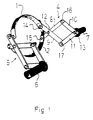
- Figure 1 shows a lifting device according to the invention.
- Figure 2 shows a lifting device according to the invention applied to the upper part of a gas bottle.
- the device shown in figure 1 includes two gripping means 1, 2, which are connected to each other by two identical linking systems 4, 5.
- the link system which comprises parallelogram four-bar linkage so arranged that the gripping devices 1, 2 are displaced parallel relative to each other when the handles 6, 7 are moved in a direction at right angle to a plane through the gripping devices, i.e. the handles in practice are moved upwards or downwards in order to open respectively close the gripping device.
- Each linkage system has two lower link arms 8, 9 and two upper link arms 10, 11.
- the lower link members are movably connected to either of the two gripping devices by means of movable pivot links constituted by pins 14, 15.
- the lower links are also movably connected to each other at a pivot 12 and with the upper link members 10, 11 at pivots 16, 17.
- the upper link members 10, 11 are further movably connected to each other at a pivot 13 which suitably is the outer end of a shaft which includes the handle 7.
- the device In use the device is applied to a gas bottle 3 as shown in figure 2.
- the gripping devices are positioned at a suitable height for lifting and moving the gas bottle.
- the gripping devices 1, 2 are actuated by the linking system and moved towards each other.
- the gripping devices which are suitably made from steel bands having a friction increasing surface coating, have some flexibility and adapt to the shape of a gas bottle.
- the gripping deyices by individual links 14, 15 are connected into a parallelogram four-bar linkage they clamp the bottle so that the largest possible contact surface is obtained instead of taking an angular position and pressing an edge onto the bottle.
- the gripping devices press stronger against the bottle and safe grip without risk for slipping is obtained. Clamped in this way the gas bottle can now be lifted and moved by one person.
- the handles when lifting are at a correct distance above the gripping devices and the parallelogram four-bar linkage should be designed with this in mind.
- the object to be lifted shall be possible to support with the body of the person who is lifting. If the distance between the gripping device and the handles is too long or too short, there is an increased risk that the lifted object will tilt to the side, either because the lever arm between the handles and the gripping device is too short or because the gripping devices will be positioned too far down on the object.
- the distance between a line through the two handles and a plane through the middle of the gripping devices should be 150 - 400 mm, preferably about 250 mm.
- the gripping devices which in the example above are made from steel bands can be given different kinds of surface coating, for example by rubber, polyethylene or the like. In embodiments without any surface coating the surface may be knurled or treated in any other way.
- the steel bands may be substituted for by chains or wires of corresponding length.
- the linkage system can be designed in different ways as to the relative length of the links of each system and position of the pivots, especially the pivot 12 which connects the two lower links. Further one more link may be added which can extend from the upper connecting point 13 of the two upper links and at its other end carry the handles.
- the gripping devices can also have different means to support or control the objects which shall be lifted and moved.
Landscapes
- Engineering & Computer Science (AREA)
- Mechanical Engineering (AREA)
- General Engineering & Computer Science (AREA)
- Specific Conveyance Elements (AREA)
- Manipulator (AREA)
- Load-Engaging Elements For Cranes (AREA)
Claims (2)
- Hebe- und Stützvorrichtung für Gasflaschen und ähnliche Gegenstände (3) in einer senkrechten Lage, zwei gegenüberliegende Greifvorrichtungen (1, 2) zum Greifen des Gegenstandes umfassend (3), dadurch gekennzeichnet, dass die beiden gegenüberliegenden Greifvorrichtungen (1, 2) mittels zweier vierteiliger Parallelogrammgestänge (4) zum Bewegen der Greifvorrichtungen mit einander verbunden sind, dass die Handgriffe (6, 7) an den beiden vierteiligen Parallelogrammgestängen (4) so montiert sind, dass die Greifvorrichtungen in Richtung zu einander bewegt werden, wenn sie von einer hebenden Kraft in Gang gebracht werden, und dass die Greifvorrichtungen flexibel sind, so dass sie sich an die Form des zu hebenden Gegenstandes anpassen.
- Vorrichtung nach einem der vorgenannten Ansprüche, dadurch gekennzeichnet, dass der Abstand zwischen den Griffen (6, 7) und der Greifvorrichtung 150 - 400 mm, vorzugsweise etwa 250 mm, ist.
Applications Claiming Priority (3)
| Application Number | Priority Date | Filing Date | Title |
|---|---|---|---|
| SE9502992A SE508341C2 (sv) | 1995-08-30 | 1995-08-30 | Lyft- och bäranordning |
| SE9502992 | 1995-08-30 | ||
| PCT/SE1996/001072 WO1997008083A1 (en) | 1995-08-30 | 1996-08-29 | Lifting and carrying device |
Publications (2)
| Publication Number | Publication Date |
|---|---|
| EP0961745A1 EP0961745A1 (de) | 1999-12-08 |
| EP0961745B1 true EP0961745B1 (de) | 2001-12-12 |
Family
ID=20399317
Family Applications (1)
| Application Number | Title | Priority Date | Filing Date |
|---|---|---|---|
| EP96929633A Expired - Lifetime EP0961745B1 (de) | 1995-08-30 | 1996-08-29 | Hebe-und stützvorrichtung |
Country Status (5)
| Country | Link |
|---|---|
| EP (1) | EP0961745B1 (de) |
| AT (1) | ATE210585T1 (de) |
| DE (1) | DE69618033T2 (de) |
| SE (1) | SE508341C2 (de) |
| WO (1) | WO1997008083A1 (de) |
Families Citing this family (3)
| Publication number | Priority date | Publication date | Assignee | Title |
|---|---|---|---|---|
| GB2407529B (en) * | 2003-10-29 | 2005-10-12 | Lionel Foster | Compressed gas storage cylinder vertical lifting clamp |
| WO2008059241A2 (en) * | 2006-11-14 | 2008-05-22 | Nutec Medical Limited | Carrier device |
| DE102006055240A1 (de) * | 2006-11-21 | 2008-05-29 | Thomas Leiber | Vorrichtung zum Anheben und Transportieren von schweren zylindrischen Körpern |
Family Cites Families (5)
| Publication number | Priority date | Publication date | Assignee | Title |
|---|---|---|---|---|
| US911996A (en) * | 1907-12-13 | 1909-02-09 | Paul O Kaffke | Lifting-tongs for fruit-jars. |
| DE1506525C3 (de) * | 1967-06-28 | 1974-10-10 | Adolf Langhammer Kg, Maschinenfabrik, 6606 Gersweiler | Greifer für Bandbunde, insbesondere Papierrollen |
| DE1756613A1 (de) * | 1968-06-15 | 1970-10-22 | Holm Dr Ing Otto | Greifer |
| SE464021B (sv) * | 1987-04-30 | 1991-02-25 | Artic Nova Ab | Lyftdon foer lyft av foeremaal |
| DK259889A (da) * | 1989-05-26 | 1990-11-27 | Kai Boersting Pedersen | Fremgangsmaade og apparat til haandtering af transportbeholdere, fortrinsvis gasflasker |
-
1995
- 1995-08-30 SE SE9502992A patent/SE508341C2/sv not_active IP Right Cessation
-
1996
- 1996-08-29 DE DE69618033T patent/DE69618033T2/de not_active Expired - Lifetime
- 1996-08-29 WO PCT/SE1996/001072 patent/WO1997008083A1/en not_active Ceased
- 1996-08-29 AT AT96929633T patent/ATE210585T1/de not_active IP Right Cessation
- 1996-08-29 EP EP96929633A patent/EP0961745B1/de not_active Expired - Lifetime
Also Published As
| Publication number | Publication date |
|---|---|
| DE69618033D1 (de) | 2002-01-24 |
| SE9502992D0 (sv) | 1995-08-30 |
| SE508341C2 (sv) | 1998-09-28 |
| WO1997008083A1 (en) | 1997-03-06 |
| DE69618033T2 (de) | 2002-08-01 |
| ATE210585T1 (de) | 2001-12-15 |
| EP0961745A1 (de) | 1999-12-08 |
| SE9502992L (sv) | 1997-03-01 |
Similar Documents
| Publication | Publication Date | Title |
|---|---|---|
| AU617021B2 (en) | Device for clamping container | |
| US5398983A (en) | Gripping apparatus | |
| US8485773B2 (en) | Device for moving large containers | |
| CA2480376C (en) | Article handling apparatus | |
| EP0542168A1 (de) | Fahrzeug mit Selbstantrieb zum Klettern längs mastförmiger Elemente wie Baumstämme, Pfähle und dergleichen | |
| US5580073A (en) | Transportation dolly | |
| US6089545A (en) | Converter for converting a conventional car jack into a transmission jack | |
| US6276732B1 (en) | Lifting device | |
| US10662002B2 (en) | Tire manipulator | |
| US5795003A (en) | Apparatus for gripping and weight-different clamping of workpieces, bar guides and the like to be held or moved relative to a location | |
| WO1997008083A1 (en) | Lifting and carrying device | |
| NL2005077A (en) | Self clamping lifting clamp. | |
| US5755476A (en) | Hoist lock | |
| GB2279030A (en) | Lifting device | |
| GB2207384A (en) | Pipe handling tool | |
| US5873615A (en) | Grapple | |
| US5042962A (en) | Barrel mover | |
| GB2328428A (en) | Block liftinng tool | |
| US20230060724A1 (en) | High-flexibility gripper | |
| US6209938B1 (en) | Lifting tool for safe 90 degree rotation | |
| EP0751090B1 (de) | Transportvorrichtung | |
| EP1509474A1 (de) | Hubvorrichtung für zellstoffballen | |
| JPH0452045B2 (de) | ||
| CN210149379U (zh) | 一种电梯反绳轮的搬运装置 | |
| DE10221766B4 (de) | Greifvorrichtung |
Legal Events
| Date | Code | Title | Description |
|---|---|---|---|
| PUAI | Public reference made under article 153(3) epc to a published international application that has entered the european phase |
Free format text: ORIGINAL CODE: 0009012 |
|
| 17P | Request for examination filed |
Effective date: 19980211 |
|
| AK | Designated contracting states |
Kind code of ref document: A1 Designated state(s): AT DE DK FI FR GB NL |
|
| 17Q | First examination report despatched |
Effective date: 20000531 |
|
| GRAG | Despatch of communication of intention to grant |
Free format text: ORIGINAL CODE: EPIDOS AGRA |
|
| GRAG | Despatch of communication of intention to grant |
Free format text: ORIGINAL CODE: EPIDOS AGRA |
|
| GRAH | Despatch of communication of intention to grant a patent |
Free format text: ORIGINAL CODE: EPIDOS IGRA |
|
| GRAH | Despatch of communication of intention to grant a patent |
Free format text: ORIGINAL CODE: EPIDOS IGRA |
|
| GRAA | (expected) grant |
Free format text: ORIGINAL CODE: 0009210 |
|
| AK | Designated contracting states |
Kind code of ref document: B1 Designated state(s): AT DE DK FI FR GB NL |
|
| PG25 | Lapsed in a contracting state [announced via postgrant information from national office to epo] |
Ref country code: NL Free format text: LAPSE BECAUSE OF FAILURE TO SUBMIT A TRANSLATION OF THE DESCRIPTION OR TO PAY THE FEE WITHIN THE PRESCRIBED TIME-LIMIT Effective date: 20011212 Ref country code: FI Free format text: LAPSE BECAUSE OF FAILURE TO SUBMIT A TRANSLATION OF THE DESCRIPTION OR TO PAY THE FEE WITHIN THE PRESCRIBED TIME-LIMIT Effective date: 20011212 Ref country code: AT Free format text: LAPSE BECAUSE OF FAILURE TO SUBMIT A TRANSLATION OF THE DESCRIPTION OR TO PAY THE FEE WITHIN THE PRESCRIBED TIME-LIMIT Effective date: 20011212 |
|
| REF | Corresponds to: |
Ref document number: 210585 Country of ref document: AT Date of ref document: 20011215 Kind code of ref document: T |
|
| REG | Reference to a national code |
Ref country code: GB Ref legal event code: IF02 |
|
| REF | Corresponds to: |
Ref document number: 69618033 Country of ref document: DE Date of ref document: 20020124 |
|
| PG25 | Lapsed in a contracting state [announced via postgrant information from national office to epo] |
Ref country code: DK Free format text: LAPSE BECAUSE OF FAILURE TO SUBMIT A TRANSLATION OF THE DESCRIPTION OR TO PAY THE FEE WITHIN THE PRESCRIBED TIME-LIMIT Effective date: 20020312 |
|
| ET | Fr: translation filed |
Inventor name: ZORN, MICHAEL |
|
| NLV1 | Nl: lapsed or annulled due to failure to fulfill the requirements of art. 29p and 29m of the patents act |
Inventor name: ZORN, MICHAEL |
|
| PLBE | No opposition filed within time limit |
Free format text: ORIGINAL CODE: 0009261 |
|
| STAA | Information on the status of an ep patent application or granted ep patent |
Free format text: STATUS: NO OPPOSITION FILED WITHIN TIME LIMIT |
|
| 26N | No opposition filed | ||
| NLV1 | Nl: lapsed or annulled due to failure to fulfill the requirements of art. 29p and 29m of the patents act | ||
| PGFP | Annual fee paid to national office [announced via postgrant information from national office to epo] |
Ref country code: DE Payment date: 20130826 Year of fee payment: 18 |
|
| PGFP | Annual fee paid to national office [announced via postgrant information from national office to epo] |
Ref country code: FR Payment date: 20130902 Year of fee payment: 18 Ref country code: GB Payment date: 20130828 Year of fee payment: 18 |
|
| REG | Reference to a national code |
Ref country code: DE Ref legal event code: R119 Ref document number: 69618033 Country of ref document: DE |
|
| GBPC | Gb: european patent ceased through non-payment of renewal fee |
Effective date: 20140829 |
|
| REG | Reference to a national code |
Ref country code: FR Ref legal event code: ST Effective date: 20150430 |
|
| PG25 | Lapsed in a contracting state [announced via postgrant information from national office to epo] |
Ref country code: DE Free format text: LAPSE BECAUSE OF NON-PAYMENT OF DUE FEES Effective date: 20150303 Ref country code: GB Free format text: LAPSE BECAUSE OF NON-PAYMENT OF DUE FEES Effective date: 20140829 |
|
| PG25 | Lapsed in a contracting state [announced via postgrant information from national office to epo] |
Ref country code: FR Free format text: LAPSE BECAUSE OF NON-PAYMENT OF DUE FEES Effective date: 20140901 |