EP0961583B1 - vorrichtung zum befestigen eines knochenblocks in einem knochentunnel - Google Patents
vorrichtung zum befestigen eines knochenblocks in einem knochentunnel Download PDFInfo
- Publication number
- EP0961583B1 EP0961583B1 EP98902498A EP98902498A EP0961583B1 EP 0961583 B1 EP0961583 B1 EP 0961583B1 EP 98902498 A EP98902498 A EP 98902498A EP 98902498 A EP98902498 A EP 98902498A EP 0961583 B1 EP0961583 B1 EP 0961583B1
- Authority
- EP
- European Patent Office
- Prior art keywords
- trocar
- sleeve
- bone
- bone block
- femur
- Prior art date
- Legal status (The legal status is an assumption and is not a legal conclusion. Google has not performed a legal analysis and makes no representation as to the accuracy of the status listed.)
- Expired - Lifetime
Links
- 210000000988 bone and bone Anatomy 0.000 title claims description 184
- 210000000689 upper leg Anatomy 0.000 claims description 46
- 210000002303 tibia Anatomy 0.000 claims description 12
- 238000005553 drilling Methods 0.000 claims description 10
- 239000000463 material Substances 0.000 claims description 8
- 238000004891 communication Methods 0.000 claims description 2
- 239000003356 suture material Substances 0.000 claims 1
- 239000002184 metal Substances 0.000 description 20
- 238000000034 method Methods 0.000 description 18
- 210000003041 ligament Anatomy 0.000 description 13
- 230000000712 assembly Effects 0.000 description 7
- 238000000429 assembly Methods 0.000 description 7
- 238000003780 insertion Methods 0.000 description 7
- 230000037431 insertion Effects 0.000 description 7
- 230000000717 retained effect Effects 0.000 description 7
- 210000000629 knee joint Anatomy 0.000 description 6
- 210000001519 tissue Anatomy 0.000 description 6
- 208000014674 injury Diseases 0.000 description 5
- 208000027418 Wounds and injury Diseases 0.000 description 4
- 230000006378 damage Effects 0.000 description 4
- 210000002435 tendon Anatomy 0.000 description 3
- 229920000954 Polyglycolide Polymers 0.000 description 2
- 210000001264 anterior cruciate ligament Anatomy 0.000 description 2
- 230000000694 effects Effects 0.000 description 2
- 210000003127 knee Anatomy 0.000 description 2
- 239000004633 polyglycolic acid Substances 0.000 description 2
- 238000001356 surgical procedure Methods 0.000 description 2
- 206010024453 Ligament sprain Diseases 0.000 description 1
- 241000124008 Mammalia Species 0.000 description 1
- 208000010040 Sprains and Strains Diseases 0.000 description 1
- 238000004873 anchoring Methods 0.000 description 1
- 230000000386 athletic effect Effects 0.000 description 1
- 230000009286 beneficial effect Effects 0.000 description 1
- 229910010293 ceramic material Inorganic materials 0.000 description 1
- 230000035876 healing Effects 0.000 description 1
- 230000000149 penetrating effect Effects 0.000 description 1
- 230000035515 penetration Effects 0.000 description 1
- 239000004033 plastic Substances 0.000 description 1
- 229920003023 plastic Polymers 0.000 description 1
- 239000004626 polylactic acid Substances 0.000 description 1
- 210000000323 shoulder joint Anatomy 0.000 description 1
- 210000004872 soft tissue Anatomy 0.000 description 1
- 230000008736 traumatic injury Effects 0.000 description 1
Images













Classifications
-
- A—HUMAN NECESSITIES
- A61—MEDICAL OR VETERINARY SCIENCE; HYGIENE
- A61F—FILTERS IMPLANTABLE INTO BLOOD VESSELS; PROSTHESES; DEVICES PROVIDING PATENCY TO, OR PREVENTING COLLAPSING OF, TUBULAR STRUCTURES OF THE BODY, e.g. STENTS; ORTHOPAEDIC, NURSING OR CONTRACEPTIVE DEVICES; FOMENTATION; TREATMENT OR PROTECTION OF EYES OR EARS; BANDAGES, DRESSINGS OR ABSORBENT PADS; FIRST-AID KITS
- A61F2/00—Filters implantable into blood vessels; Prostheses, i.e. artificial substitutes or replacements for parts of the body; Appliances for connecting them with the body; Devices providing patency to, or preventing collapsing of, tubular structures of the body, e.g. stents
- A61F2/02—Prostheses implantable into the body
- A61F2/08—Muscles; Tendons; Ligaments
- A61F2/0805—Implements for inserting tendons or ligaments
-
- A—HUMAN NECESSITIES
- A61—MEDICAL OR VETERINARY SCIENCE; HYGIENE
- A61B—DIAGNOSIS; SURGERY; IDENTIFICATION
- A61B17/00—Surgical instruments, devices or methods
- A61B17/16—Instruments for performing osteoclasis; Drills or chisels for bones; Trepans
- A61B17/17—Guides or aligning means for drills, mills, pins or wires
- A61B17/1714—Guides or aligning means for drills, mills, pins or wires for applying tendons or ligaments
-
- A—HUMAN NECESSITIES
- A61—MEDICAL OR VETERINARY SCIENCE; HYGIENE
- A61B—DIAGNOSIS; SURGERY; IDENTIFICATION
- A61B17/00—Surgical instruments, devices or methods
- A61B17/16—Instruments for performing osteoclasis; Drills or chisels for bones; Trepans
- A61B17/17—Guides or aligning means for drills, mills, pins or wires
- A61B17/1739—Guides or aligning means for drills, mills, pins or wires specially adapted for particular parts of the body
- A61B17/1764—Guides or aligning means for drills, mills, pins or wires specially adapted for particular parts of the body for the knee
-
- A—HUMAN NECESSITIES
- A61—MEDICAL OR VETERINARY SCIENCE; HYGIENE
- A61F—FILTERS IMPLANTABLE INTO BLOOD VESSELS; PROSTHESES; DEVICES PROVIDING PATENCY TO, OR PREVENTING COLLAPSING OF, TUBULAR STRUCTURES OF THE BODY, e.g. STENTS; ORTHOPAEDIC, NURSING OR CONTRACEPTIVE DEVICES; FOMENTATION; TREATMENT OR PROTECTION OF EYES OR EARS; BANDAGES, DRESSINGS OR ABSORBENT PADS; FIRST-AID KITS
- A61F2/00—Filters implantable into blood vessels; Prostheses, i.e. artificial substitutes or replacements for parts of the body; Appliances for connecting them with the body; Devices providing patency to, or preventing collapsing of, tubular structures of the body, e.g. stents
- A61F2/02—Prostheses implantable into the body
- A61F2/08—Muscles; Tendons; Ligaments
- A61F2/0811—Fixation devices for tendons or ligaments
-
- A—HUMAN NECESSITIES
- A61—MEDICAL OR VETERINARY SCIENCE; HYGIENE
- A61F—FILTERS IMPLANTABLE INTO BLOOD VESSELS; PROSTHESES; DEVICES PROVIDING PATENCY TO, OR PREVENTING COLLAPSING OF, TUBULAR STRUCTURES OF THE BODY, e.g. STENTS; ORTHOPAEDIC, NURSING OR CONTRACEPTIVE DEVICES; FOMENTATION; TREATMENT OR PROTECTION OF EYES OR EARS; BANDAGES, DRESSINGS OR ABSORBENT PADS; FIRST-AID KITS
- A61F2/00—Filters implantable into blood vessels; Prostheses, i.e. artificial substitutes or replacements for parts of the body; Appliances for connecting them with the body; Devices providing patency to, or preventing collapsing of, tubular structures of the body, e.g. stents
- A61F2/02—Prostheses implantable into the body
- A61F2/08—Muscles; Tendons; Ligaments
- A61F2/0811—Fixation devices for tendons or ligaments
- A61F2002/0817—Structure of the anchor
- A61F2002/0823—Modular anchors comprising a plurality of separate parts
- A61F2002/0829—Modular anchors comprising a plurality of separate parts without deformation of anchor parts, e.g. fixation screws on bone surface, extending barbs, cams, butterflies, spring-loaded pins
-
- A—HUMAN NECESSITIES
- A61—MEDICAL OR VETERINARY SCIENCE; HYGIENE
- A61F—FILTERS IMPLANTABLE INTO BLOOD VESSELS; PROSTHESES; DEVICES PROVIDING PATENCY TO, OR PREVENTING COLLAPSING OF, TUBULAR STRUCTURES OF THE BODY, e.g. STENTS; ORTHOPAEDIC, NURSING OR CONTRACEPTIVE DEVICES; FOMENTATION; TREATMENT OR PROTECTION OF EYES OR EARS; BANDAGES, DRESSINGS OR ABSORBENT PADS; FIRST-AID KITS
- A61F2/00—Filters implantable into blood vessels; Prostheses, i.e. artificial substitutes or replacements for parts of the body; Appliances for connecting them with the body; Devices providing patency to, or preventing collapsing of, tubular structures of the body, e.g. stents
- A61F2/02—Prostheses implantable into the body
- A61F2/08—Muscles; Tendons; Ligaments
- A61F2/0811—Fixation devices for tendons or ligaments
- A61F2002/0847—Mode of fixation of anchor to tendon or ligament
- A61F2002/0852—Fixation of a loop or U-turn, e.g. eyelets, anchor having multiple holes
-
- A—HUMAN NECESSITIES
- A61—MEDICAL OR VETERINARY SCIENCE; HYGIENE
- A61F—FILTERS IMPLANTABLE INTO BLOOD VESSELS; PROSTHESES; DEVICES PROVIDING PATENCY TO, OR PREVENTING COLLAPSING OF, TUBULAR STRUCTURES OF THE BODY, e.g. STENTS; ORTHOPAEDIC, NURSING OR CONTRACEPTIVE DEVICES; FOMENTATION; TREATMENT OR PROTECTION OF EYES OR EARS; BANDAGES, DRESSINGS OR ABSORBENT PADS; FIRST-AID KITS
- A61F2/00—Filters implantable into blood vessels; Prostheses, i.e. artificial substitutes or replacements for parts of the body; Appliances for connecting them with the body; Devices providing patency to, or preventing collapsing of, tubular structures of the body, e.g. stents
- A61F2/02—Prostheses implantable into the body
- A61F2/08—Muscles; Tendons; Ligaments
- A61F2/0811—Fixation devices for tendons or ligaments
- A61F2002/0847—Mode of fixation of anchor to tendon or ligament
- A61F2002/0864—Fixation of tendon or ligament between anchor elements, e.g. by additional screws in the anchor, anchor crimped around tendon
-
- A—HUMAN NECESSITIES
- A61—MEDICAL OR VETERINARY SCIENCE; HYGIENE
- A61F—FILTERS IMPLANTABLE INTO BLOOD VESSELS; PROSTHESES; DEVICES PROVIDING PATENCY TO, OR PREVENTING COLLAPSING OF, TUBULAR STRUCTURES OF THE BODY, e.g. STENTS; ORTHOPAEDIC, NURSING OR CONTRACEPTIVE DEVICES; FOMENTATION; TREATMENT OR PROTECTION OF EYES OR EARS; BANDAGES, DRESSINGS OR ABSORBENT PADS; FIRST-AID KITS
- A61F2/00—Filters implantable into blood vessels; Prostheses, i.e. artificial substitutes or replacements for parts of the body; Appliances for connecting them with the body; Devices providing patency to, or preventing collapsing of, tubular structures of the body, e.g. stents
- A61F2/02—Prostheses implantable into the body
- A61F2/08—Muscles; Tendons; Ligaments
- A61F2/0811—Fixation devices for tendons or ligaments
- A61F2002/0847—Mode of fixation of anchor to tendon or ligament
- A61F2002/087—Anchor integrated into tendons, e.g. bone blocks, integrated rings
-
- A—HUMAN NECESSITIES
- A61—MEDICAL OR VETERINARY SCIENCE; HYGIENE
- A61F—FILTERS IMPLANTABLE INTO BLOOD VESSELS; PROSTHESES; DEVICES PROVIDING PATENCY TO, OR PREVENTING COLLAPSING OF, TUBULAR STRUCTURES OF THE BODY, e.g. STENTS; ORTHOPAEDIC, NURSING OR CONTRACEPTIVE DEVICES; FOMENTATION; TREATMENT OR PROTECTION OF EYES OR EARS; BANDAGES, DRESSINGS OR ABSORBENT PADS; FIRST-AID KITS
- A61F2/00—Filters implantable into blood vessels; Prostheses, i.e. artificial substitutes or replacements for parts of the body; Appliances for connecting them with the body; Devices providing patency to, or preventing collapsing of, tubular structures of the body, e.g. stents
- A61F2/02—Prostheses implantable into the body
- A61F2/08—Muscles; Tendons; Ligaments
- A61F2/0811—Fixation devices for tendons or ligaments
- A61F2002/0876—Position of anchor in respect to the bone
- A61F2002/0882—Anchor in or on top of a bone tunnel, i.e. a hole running through the entire bone
Definitions
- This invention relates to apparatus in general for fixing bone blocks in bone tunnels.
- Tissue detachment may occur as the result of an accident such as a fall, overexertion during a work-related activity, during the course of an athletic event, or in any one of many other situations and/or activities. Such injuries are generally the result of excess stress being placed on the tissues.
- the graft ligament extends back out of the femoral tunnel, across the interior of the knee joint, and then through the tibial tunnel.
- the free end of the graft ligament resides outside the tibia, at the anterior side of the tibia.
- a bone screw is inserted between the bone block and the wall of femoral bone tunnel so as to securely lock the bone block in position by a tight interference fit.
- the free end of the graft ligament is securely attached to the tibia.
- cross-pinning In order to provide for proper cross-pinning of the bone block in the bone tunnel, a drill guide is generally used.
- the drill guide serves to ensure that the transverse passage is positioned in the bone so that it will intersect the appropriate tunnel section and the bone block. Drill guides for use in effecting such transverse drilling are shown in U.S. Patents Nos. 4,901,711 ; 4,985,032 ; 5,152,764 ; 5,350,380 ; and 5,431,651 .
- a cross-pin screw may be formed out of a material which may be absorbed by the body over time, thereby eliminating any need for the cross-pin screw to be removed in a subsequent surgical procedure.
- absorbable cross-pin screws as are presently known in the art lack sufficient strength to be passed directly into the bone and the bone block. Accordingly, to use absorbable cross-pin screws, one must first drill a hard metal drilling implement into the bone and bone block, remove the drilling implement, and then replace the drilling implement with the absorbable cross-pin screw. However, removal of the hard metal drilling implement often permits the bone block to shift in the tunnel, such that the subsequent insertion of the absorbable cross-pin screw becomes impossible.
- the object of the present invention is, therefore, to provide devices which can be used for fixing a bone block in a bone tunnel such that the bone block is retained in the tunnel by cross-pins which are made of a material which is absorbable by the body.
- Use of said rack assembly comprises the steps of placing the bone block in the bone tunnel, and then advancing spaced-apart first and second drill means through the bone transversely of the bone tunnel so as to intersect the bone block and extend therethrough. This further includes the steps of removing one of the drill means and replacing the one removed drill means with a first absorbable rod, and then removing the other of the drill means and replacing the other removed drill means with a second absorbable rod, whereby the bone block will be retained in the bone tunnel with the absorbable rods.
- the first and second drill means may comprise metal wires.
- An alternative method for fixing a bone block in a bone tunnel by using said rack assembly comprises the steps of placing the bone block in the bone tunnel, and then advancing spaced-apart first and second trocar and sleeve assemblies through the bone, transversely of the bone tunnel, so as to intersect the bone block and extend therethrough, the trocar in each of the assemblies being disposed within one of the sleeves of the assemblies and substantially filling the sleeve.
- This further includes the steps of removing the trocar from the first of the sleeves, advancing a first absorbable rod through the first sleeve and through the bone block, and then removing the first sleeve, so as to leave the first absorbable rod in the bone and the bone block.
- Another alternative method for fixing a bone block in a bone by using said rack assembly tunnel comprises the placing of the bone block in the bone tunnel, and then advancing spaced-apart first and second trocar and sleeve assemblies through the bone transversely of the bone tunnel so as to intersect the bone block and extend therethrough, the trocar in each of the assemblies being disposed within one of the sleeves of the assemblies and substantially filling the sleeve.
- This further includes the steps of removing the trocar from the sleeves, advancing absorbable rods through the sleeves and through the bone block, and then removing the sleeves from the bone block and the bone, so as to leave the absorbable rods in the bone block and the bone, whereby the bone block will be retained in the bone tunnel with the absorbable rods.
- a rack assembly for cross-pinning a bone block in a bone tunnel in a human femur, the rack assembly comprising an L-shaped member having a base portion and an arm portion extending transversely of the base portion, and a cannulated sleeve for movement through a tibia and into the femur and for disposition in the femoral bone tunnel, the cannulated sleeve having an enlarged head portion at a free end thereof for disposition in the bone tunnel in the femur and being connectable to the base portion of the L-shaped member at an opposite end thereof.
- the rack assembly further includes a trocar sleeve guide member removably connectable to the arm portion of the L-shaped member and having bores extending therethrough at an angle normal to a longitudinal axis of the cannulated sleeve's head portion, first and second trocar sleeves for movable disposition in the bores, respectively, and at least one trocar for disposition in the trocar sleeves, the trocar being interconnectable with the trocar sleeve in which the trocar is disposed such that the trocar sleeve and the trocar therein are movable axially toward the cannulated sleeve's head portion and rotatable together, such that the interconnected trocar and trocar sleeve are adapted for drilling into the femur and the bone block in accordance with the features of claim 1.
- the trocar is removable from the trocar sleeves, and absorbable rods are provided for sliding through the trocar sleeves and through the bone block, the trocar sleeves being removable from the bone block and the femur and from the absorbable rods, so as to leave the absorbable rods in the bone block and the femur.
- the rack assembly for cross-pinning a bone block in a bone tunnel in a human femur.
- the rack assembly comprises an L-shaped member having a base portion and an arm portion extending transversely of the base portion, and a rod shaped cannulated sleeve for movement through the femur until a free end thereof is disposed adjacent to the bone block, with an opposite end thereof being connectable to the base portion of the L-shaped member.
- a trocar sleeve guide member is removably connectable to the arm portion of the L-shaped member and is provided with at least two bores extending therethrough at an angle normal to a hypothetical extension of a longitudinal axis of the cannulated sleeve.
- First and second trocar sleeves are provided for movable disposition in the bores, respectively.
- At least one trocar is provided for disposition in the trocar sleeves, the trocar being interconnnectable with the trocar sleeve in which the trocar is disposed such that the trocar sleeve and the trocar therein are movable axially toward the bone block and rotatable together, such that the interconnected trocar and trocar sleeve are adapted for drilling into the femur and the bone block.
- the trocar is removable from the trocar sleeves, and absorbable rods are slidable through the trocar sleeves and through the bone block, the trocar sleeves being removable from the bone block and the femur and from the absorbable rods so as to leave the absorbable rods in the bone block and the femur.
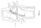
- a human knee joint 10 including a femur 12 and tibia 14, has been provided with an appropriate femoral bone tunnel 16 and an appropriate tibial bone tunnel 18.
- Such tunnels may be provided in ways well known in the art.
- a bone block 20, having ligament material 22 attached thereto, has been positioned in femoral tunnel 16. Such bone block positioning may also be achieved in ways well known in the art.
- a first metal wire 30, which may be of the type commonly referred to as a guidewire or a "K-wire", is advanced through skin 31 and a first portion 32 of femur 12.
- First wire 30 is advanced transversely of femoral tunnel 16 so as to intersect and extend through bone block 20, as shown in Fig. 2 .
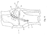
- a second metal wire 34 is advanced through a second portion 36 of femur 12.
- Second wire 34 is also advanced transversely of femoral tunnel 16 so as to also intersect and extend through bone block 20 ( Fig. 3 ). At this point, bone block 20 is securely held in femoral tunnel 16 by the two spaced-apart metal wires 30, 34.
- one of the two wires 30, 34 is then removed, while the other of the two wires 30, 34 is left in place in femur 12 and bone block 20.
- wire 30 may be removed while wire 34 is left in place.
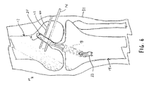
- a first absorbable rod 40 ( Fig. 5 ) is then advanced through the bore 42 left by the removal of first wire 30, such that first absorbable rod 40 extends through femur 12 and bone block 20 ( Fig. 6 ). At this point, bone block 20 is securely held in femoral tunnel 16 by both metal wire 34 and first absorbable rod 40.
- the absorbable rods 40, 44 may be made out of a material such as polylactic acid (PLA), polyglycolic acid (PGA), polydiaxanone (PDS), or out of some other such material which is formable into a relatively rigid and hard configuration, but which is absorbable by the body of the patient over time. If desired, the distal ends of absorbable rods 40, 44 can be pointed or rounded so as to facilitate their deployment into the body.
- PLA polylactic acid
- PGA polyglycolic acid
- PDS polydiaxanone
- a bone block is fixed within a bone tunnel, such that the bone block is anchored in the tunnel by cross-pins which are made out of a material which is absorbable by the body over time.
- the method may be exercised with any reasonable number of wires, exceeding one.
- the method includes the steps of placing the bone block in the bone tunnel, and then advancing a plurality of metal wires through the bone, transversely of the tunnel, so as to intercept the bone block and extend therethrough. At least one of the wires is then removed while leaving at least one of the wires in place, and that at least one removed wire is then replaced by at least one absorbable rod. At least one further of the wires is then removed and that at least one removed wire is then replaced by at least one further absorbable rod. The last-mentioned step is then repeated until a selected number of the metal wires is each replaced with an absorbable rod, whereby to retain the bone block in the bone tunnel with absorbable rods.
- Figs. 1-9 show metal wires 30, 34 and absorbable rods 40, 44 passing completely through bone block 20 during the cross-pinning procedure, it is also possible for metal wires 30, 34 and absorbable rods 40, 44 to pass only part way across bone block 20, if the same should be desired.
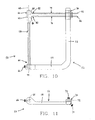
- Figs. 10-17 show a novel rack assembly 50 according to the present invention.
- Rack assembly 50 comprises an L-shaped member 52 having a base portion 54 and an arm portion 56.
- the arm portion 56 extends transversely, and preferably is normal to, base portion 54.
- Rack assembly 50 also includes a cannulated sleeve 58 which, at a first end 60 thereof, is provided with an enlarged head portion 62, and which, at a second end 64 thereof, is releasably connectable to base portion 54 of L-shaped member 52.
- Sleeve 58 may be retained in a bore 65 ( Fig. 11 ) formed in base portion 54 by a set screw 66.
- a trocar sleeve guide member 70 is removably connectable to arm portion 56 of L-shaped member 52.
- Trocar sleeve guide member 70 is provided with bores 72 extending therethrough. Bores 72 extend substantially normal to a longitudinal axis 68 ( Fig. 10 ) of the enlarged head portion 62 of cannulated sleeve 58.
- a set screw 71 ( Fig. 11 ) may be used to releasably retain trocar sleeve guide member 70 in position on arm portion 56.
- arm portion 56 may be provided with stop means (not shown) for limiting the movement of the trocar sleeve guide member 70 along arm portion 56.
- Trocar sleeve guide member 70 is preferably formed in two halves releasably held together by a set screw 73 ( Fig. 11 ), whereby trocar sleeve guide member 70 can be slidably mounted on, or detached from, trocar sleeves 74, 76 passing through bores 72, as will hereinafter be discussed.
- First and second trocar sleeves 74, 76 are slidably received by bores 72, such that sleeves 74, 76 are axially and rotatably movable in bores 72.
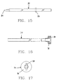
- trocar sleeve 74 is provided with a collar portion 78 having a slot 80 formed therein.
- Sleeve 76 is substantially identical to sleeve 74.
- Rack assembly 50 also includes one or more trocars 82 ( Figs. 10 and 15 ) for disposition in the sleeves 74, 76.
- Each trocar 82 is provided with a sharp end 84 ( Fig. 15 ) for penetration of bone.
- a transversely-extending pin 86 is provided near (but spaced from) the opposite end of the trocar 82. Pin 86 is fixed in place and is receivable by the slots 80 of trocar sleeves 74, 76 such that axial (in a distal direction) and rotational movement of trocar 82 causes similar movement of sleeves 74, 76.
- the first and second absorbable rods 40, 44 are slidable through sleeves 74, 76, as will be further described hereinbelow.
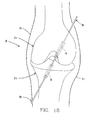
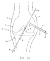
- Figs. 18-28 illustrate how rack assembly 50 may be used.
- a human knee joint 10 including femur 12 and tibia 14.
- An appropriate femoral tunnel 16 and an appropriate tibial tunnel 18 have been provided, as by means and methods well known in the art.
- a guidewire 90 extends through the bone tunnels 16, 18 as shown.
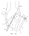
- the rack assembly's cannulated sleeve 58 is fed over guidewire 90, through tibial tunnel 18 and into femoral tunnel 16, until the cannulated sleeve's head portion 62 engages an annular shoulder 92 in femoral tunnel 16 ( Fig. 19 ).
- guidewire 90 extends through a bore 94 ( Figs. 10 and 19 ) formed in base portion 54 of L-shaped member 52.
- the cannulated sleeve's head portion 62 is preferably sized so as to form a snug fit in femoral tunnel 16.
- Cannulated sleeve 58 may be positioned in the bone tunnels 16, 18 and then connected to L-shaped member 52 or, more preferably, cannulated sleeve 58 may be first connected to L-shaped member 52 and then positioned in femur 12 and tibia 14. Trocar sleeve guide member 70, if not already positioned on arm portion 56, is then fixed to arm portion 56, as by set screw 71 ( Fig. 11 ).
- First trocar sleeve 74 is then inserted in a bore 72 of guide member 70 ( Fig. 20 ), and trocar 82 is extended through sleeve 74 until pin 86 ( Fig. 15 ) of trocar 82 is nested in slot 80 ( Figs. 16 and 17 ) of sleeve 74, with the trocar's sharp end 84 extending beyond the distal end of sleeve 74 ( Fig. 20 ).
- trocar 82 may be mounted in first trocar sleeve 74 before first trocar sleeve 74 is mounted in a bore 72.
- trocar sleeve 74 and trocar 82 are then drilled, as a unit, into femur 12 toward, but short of, the enlarged head portion 62 of cannulated sleeve 58 ( Fig. 20 ).
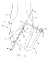
- Trocar 82 may then be withdrawn from first trocar sleeve 74 and placed in second trocar sleeve 76 ( Fig. 21 ).
- a second trocar 82 may be provided for second trocar sleeve 76.
- the combination of trocar sleeve 76 and trocar 82 is then drilled, as a unit, into femur 12 toward, but short of, head portion 62 of cannulated sleeve 58.
- the rack's L-shaped member 52 may then be removed from the surgical site. This may be accomplished by first loosening set screw 73 ( Fig.
- trocar sleeves 74, 76 will be freed from guide member 70, and then sliding cannulated sleeve 58 downward along guidewire 90 until the cannulated sleeve emerges from bone tunnels 16, 18. This procedure will leave trocar sleeves 74, 76 lodged in femur 12 ( Fig. 22 ).
- Guidewire 90 is then used to pull a suture 96, which is attached to bone block 20, up through tibial tunnel 18 and into femoral tunnel 16, until bone block 20 engages the annular shoulder 92 in femoral tunnel 16 ( Fig. 23 ).
- Guidewire 90 may be provided with an eyelet (not shown) adjacent to its proximal end so as to facilitate this procedure. Bone block 20 can then be held is this position by maintaining tension on the portion of suture 96 emerging from the top of femur 12.
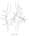
- Trocar sleeve 76 and trocar 82 are then drilled through bone block 20, as shown in Fig. 24 .
- Trocar 82 may then be removed from sleeve 76, placed in sleeve 74, and sleeve 74 and trocar 82 drilled through bone block 20, as shown in Fig. 25 .
- the trocar 82 (or trocars 82 if more than one trocar is used) may then be withdrawn from the sleeve 74 (or sleeves 74, 76).
- the first absorbable rod 40 is then inserted, by sliding rod 40 through trocar sleeve 74 into a position extending through bone block 20 ( Fig. 26 ).
- Sleeve 74 may then be withdrawn from bone block 20 and femur 12, leaving first absorbable rod 40 in place in femur 12 and extending through bone block 20, as shown in Fig. 27 .
- second absorbable rod 44 is then slid into place through sleeve 76.
- Sleeve 76 is then removed, leaving second absorbable rod 44, along with first absorbable rod 40, extending through bone block 20 so as to lock bone block 20 in place in femoral tunnel 16, as shown in Fig. 28 .
- rack assembly 50 with a guide member 70 which is not formed in two separable halves.
- guide member 70 can simply be detached from L-shaped member 52 by unscrewing set screw 71.
- Guide member 70 can then be left mounted on the outboard portions of sleeves 74, 76 until sleeves 74, 76 are withdrawn from the surgical site, with guide member 70 being removed with the last of the sleeves 74, 76.
- Figs. 29-33 show an alternative rack assembly 100 which comprises an L-shaped member 102 having a base portion 104 and an arm portion 106. Arm portion 106 extends transversely of, and preferably is normal to, base portion 104.
- Rack assembly 100 also includes a cannulated sleeve 108 which, at a base end 110 thereof, is connected to base portion 104.
- Cannulated sleeve 108 may be retained in a bore 112 in base portion 104, as by screw threads or a set screw (not shown) or a press fit or the like.
- Cannulated sleeve 108 is provided with a slot 114 ( Fig. 29 ) extending substantially throughout the length of sleeve 108.
- Base portion 104 of L-shaped member 102 is also provided with a slot 116 ( Fig. 30 ) which is alignable with the sleeve's slot 114 so as to place the slots 114, 116 in communication with each other.
- a trocar sleeve guide member 120 is removably connectable to arm portion 106 of L-shaped member 102.
- Trocar sleeve guide member 120 is provided with bores 122 extending therethrough. Bores 122 extend substantially normal to a hypothetical extension of the longitudinal axis 124 of cannulated sleeve 108.
- a set screw 126 ( Fig. 30 ) may be used to releasably retain trocar sleeve guide member 120 in position on arm portion 106.
- arm portion 106 may be provided with a stop means (not shown) for limiting movement of member 120 on arm portion 106.
- Trocar sleeve guide member 120 is preferably formed in two halves releasably held together by a set screw 127 ( Fig. 30 ), whereby trocar sleeve guide member 120 can be slidably mounted on, or detachable from, trocar sleeves 128, 130 passing through bores 122, as will hereinafter be discussed.
- First and second trocar sleeves 128, 130 are received by bores 122, such that sleeves 128, 130 are axially and rotatably movable in bores 122.
- the two trocar sleeves 128, 130 are substantially identical to the sleeve 74 shown in Figs. 16 and 17 .
- Rack assembly 100 also includes one or more trocars 132 for disposition in sleeves 128, 130.
- the trocar 132 is substantially identical to the trocar 82 shown in Fig. 15 .
- the aforementioned first and second absorbable rods 40, 44 are slidable through sleeves 128, 130.
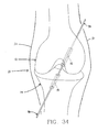
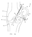
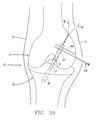
- Figs. 34-40 illustrate how rack assembly 100 may be used .
- a guidewire 90 extends through bone tunnels 16, 18.
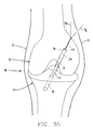
- Guidewire 90 is then used to pull a suture 96, which is attached to bone block 20, up through tibial tunnel 18 and into femoral tunnel 16, such that bone block 20 is in engagement with annular shoulder 92 ( Fig. 35 ). Bone block 20 is kept in this position by maintaining tension on the portion of suture 96 emerging from the top of femur 12.
- Suture 96 is then introduced into the rack assembly's cannulated sleeve 108 and base portion 104 by way of slots 114, 116.
- Cannulated sleeve 108 is then passed down the hole 133 ( Figs. 35 and 36 ) left by the removed guidewire 90 until the distal end of the cannulated sleeve engages the top end of bone block 20 ( Fig. 36 ).
- first trocar sleeve 128 is extended through a guide member bore 122 and a trocar 132 is inserted into sleeve 128.
- a trocar 132 may be inserted into first trocar sleeve 128 before first trocar sleeve 128 is inserted into a guide member bore 122.
- the sleeve 128 and trocar 132 are then drilled, as a unit, into femur 12. With bone block 20 held against shoulder 92 by pulling on suture 96, the combination of sleeve 128 and trocar 132 is drilled through bone block 20 ( Fig. 36 ).
- sleeve 130 and trocar 132 are then drilled through bone block 20, as shown in Fig. 37 .
- L-shaped member 102 and cannulated sleeve 108 are then removed from the surgical site. This may be accomplished by first loosening set screw 127 ( Fig. 30 ) so as to separate trocar sleeve guide member 120 into its two halves, whereby trocar sleeves 128, 130 will be freed from guide member 120, and then sliding cannulated sleeve 108 upward and out of hole 133. Any trocars 132 are then removed, leaving the trocar sleeves 128, 130 extending into femur 12 and across bone block 20, as shown in Fig. 38 .
- Second absorbable rod 44 is then slid through sleeve 130 and sleeve 130 removed ( Fig. 39 ), and first absorbable rod 40 is slid through sleeve 128 and sleeve 128 removed, leaving absorbable rods 40, 44 in place ( Fig. 40 ) holding bone block 20 locked in femoral tunnel 16..
- Suture 96 is then slipped through bone block 20 and removed, in the manner well known in the art.
- the present invention is by no means limited to the application thereof as herein disclosed and/or as shown in the drawings.
- inventive apparatus are described herein and illustrated with reference to the human knee joint. It is foreseen that the apparatus described herein will be particularly beneficial with respect to such operations. However, it will also be appreciated by those skilled in the art that the apparatus described herein find utility with respect to mammals generally, and with respect to other bones as, for example, in shoulder joints or the like.
- trocars 82 and 132 and their associated sleeves 74, 76 and 128, 130 might be passed only part way through bone block 20, but not all the way through; or sleeves 74, 76 and/or sleeves 128, 130 might be stopped short of bone block 20 while trocars 82 and/or 132 penetrate into bone block 20.
- trocars 82 and 132 are disclosed herein as being in the form of a hard rod with a sharp tip for penetrating bone.
- trocars 82 and 132 might comprise guidewires or K-wires with a pyramidal front point.
- the invention might also be practiced with trocars 82 and 132 comprising a twist drill, a spade drill and/or some other sort of drill.
- trocars 82 and/or 132 might be used with their associated rack assemblies 50 and 100, respectively, but without their associated sleeves 74, 76 and 128, 130, respectively. In this case, at least one trocar would always remain positioned in bone block 20 until at least one absorbable rod 40, 44 was positioned in the bone block.
- the present application will have utility with respect to setting cross-pins which may not necessarily be absorbable.
- the present invention will have utility wherever cross-pinning needs to be achieved for cross-pins which cannot be passed directly through the bone and/or bone block, e.g., where the cross-pins may be too soft or too brittle or too fragile to pass directly through the bone and/or bone block, or where the cross-pins may have a geometry which makes it difficult or impossible for them to be passed directly through the bone and/or bone block.
- the present invention might be used to set cross-pins made out of plastic and/or ceramic materials, or the present invention might be used to set cross-pins made out of metal.
Landscapes
- Health & Medical Sciences (AREA)
- Life Sciences & Earth Sciences (AREA)
- Orthopedic Medicine & Surgery (AREA)
- Veterinary Medicine (AREA)
- Animal Behavior & Ethology (AREA)
- Oral & Maxillofacial Surgery (AREA)
- Surgery (AREA)
- Engineering & Computer Science (AREA)
- Biomedical Technology (AREA)
- Heart & Thoracic Surgery (AREA)
- Public Health (AREA)
- General Health & Medical Sciences (AREA)
- Rheumatology (AREA)
- Cardiology (AREA)
- Vascular Medicine (AREA)
- Rehabilitation Therapy (AREA)
- Dentistry (AREA)
- Nuclear Medicine, Radiotherapy & Molecular Imaging (AREA)
- Transplantation (AREA)
- Medical Informatics (AREA)
- Molecular Biology (AREA)
- Surgical Instruments (AREA)
- Prostheses (AREA)
Claims (9)
- Eine Gestellanordnung zur kreuzweisen Verstiftung eines Knochenblocks, der in einem Knochentunnel in einem humanen Femur angeordnet ist, besagte Gestellanordnung enthaltend:ein L-förmiges Teil mit einem Basisbereich und einem Armbereich, welcher sich transversal zu besagtem Basisbereich erstreckt;eine stangenförmige kannelierte Hülse (58) zur Bewegung durch eine Tibia in das Femur und zur Anordnung in besagtem Knochentunnel im Femur, wobei besagte stangenförmige kannelierte Hülse einen vergrößerten Kopfbereich (62) an einem freien Ende (60) von ihr besitzt zur Anordnung im Knochentunnel im Femur bis deren freies Ende gegenüber besagtem Knochenblock angeordnet ist und mit dem Basisbereich des L-förmigen Teils an einem gegenüberliegenden Ende verbindbar ist;ein Führungselement (70) für die Hülse einer Hohlnadel, die lösbar verbindbar mit besagtem Armbereich des L-förmigen Teils ist und wenigstens zwei Bohrungen aufweist, die sich durch sie erstrecken mit einem Winkel, der normal zur Längsachse besagten Kopfbereichs von besagter kannelierter Hülse ist;erste und zweite Hohlnadelhülsen zur beweglichen Anordnung in den Bohrungen, insbesondere eine Hohlnadel zur Anordnung in besagten Hohlnadelhülsen, die Hohlnadel ist verbindbar mit besagter Hohlnadelhülse in welcher die Hohlnadel angeordnet ist, besagte Hohlnadelhülse und besagte Hohlnadel darin sind axial beweglich gegen besagten Kopfbereich von besagter kannelierter Hülse, die im Femur angeordnet ist und zusammen derart drehbar, dass besagte verbundene Hohlnadel und Hohlnadelhülse vorgesehen sind um in den Femur und den Knochenblock zu bohren;besagte Hohlnadel bleibt dabei entfernbar aus besagten Hohlnadelhülsen sowiebesagte Hohlnadelhülsen sind vorgesehen um Stangen aufzunehmen, die durch die Hohlnadelhülsen gleitbar sind und durch den Knochenblock, wobei besagte Hohlnadelhülsen aus dem Knochenblock und aus dem Femur und von den Stangen entfernbar sind um die Stangen im Knochenblock und dem Femur zu belassen.
- Gestellanordnung in Übereinstimmung mit Anspruch 1, wobei besagtes Führungselement (70) für die Hohlnadelhülse trennbare erste und zweite Teile einschließt.
- Gestellanordnung in Übereinstimmung mit Anspruch 1 und weiterhin enthaltend besagte Stangen.
- Gestellanordnung in Übereinstimmung mit Anspruch 3, wobei besagte Stangen aus absorbierbarem Material sind.
- Gestellanordnung in Übereinstimmung mit Anspruch 1, wobei besagte Bohrungen für das Führungsteil der Hohlnadel mit besagter kannelierter Hülse ausgerichtet sind und die Achsen besagter Bohrungen voneinander beabstandet sind von einer Ebene besagten Basisteils von besagtem L-förmigen Teil.
- Gestellanordnung (100) für die Kreuzverstiftung eines Knochenblocks, der in einem Knochentunnel eines menschlichen Femurs angeordnet ist, besagte Gestellanordnung enthaltend:ein L-förmiges Teil mit einem Basisteil (160) und einem Armteil (106) welches sich transversal von besagtem Basisteil (110) erstreckt;eine stangenförmige kannelierte Hülse (108) zur Bewegung durch den Femur bis ein freies Ende davon gegenüberliegend zu dem Knochenblock angeordnet ist und ein gegenüberliegendes Ende davon lösbar verbindbar mit besagtem Basisteil von besagtem L-förmigen Teil ist;ein Führungsteil (120) für die Hohlnadelhülse, die entfernbar verbindbar mit besagtem Armbereich (106) von besagtem L-förmigen Teil ist und wenigstens zwei Bohrungen aufweist, die sich hierdurch erstrecken unter einem Winkel, der normal zur hypothetischen Extension einer Längsachse (124) von besagter kannelierter Hülse (108) ist;erste und zweite Hohlnadelhülsen (128, 130) zur beweglichen Anordnung in besagten Bohrungen, nämlich wenigstens eine Hohlnadel zur beweglichen Anordnung in besagten Hohlnadelhülsen (128, 130), besagte Hohlnadel (132) ist verbindbar mit besagter Hohlnadelhülse (128); (130) in welcher die Hohlnadel (132) angeordnet ist, besagte Hohlnadelhülse (128); (130) und besagte Hohlnadel (132) darin ist axial gegen den Knochenblock beweglich und zusammen derart drehbar, dass besagte verbundene Hohlnadel (132) und Hohlnadelhülse (128, 130) vorgesehen sind um in den Femur und den Knochenblock zu bohren;wobei besagte Hohlnadel (132) aus besagten Hohlnadelhülsen (128; 130) entfernbar ist und besagte Hohlnadelhülsen (128, 130) vorgesehen sind um absorbierbare Stangen aufzunehmen, die durch besagte Hohlnadelhülsen und durch besagten Knochenblock rutschen;besagte Hohlnadelhülsen (128, 130) sind aus dem Knochenblock und dem Femur und von besagten absorbierbaren Stangen entfernbar derart, dass die besagte absorbierbare Stange im Knochenblock und dem Femur hinterlassen wird.
- Gestellanordnung in Übereinstimmung mit Anspruch 6 wobei das Führungselement besagter Hohlnadelhülsen trennbare erste und zweite Teile enthält.
- Gestellanordnung in Übereinstimmung mit Anspruch 6, wobei besagte kannelierte Hülse vorgesehen ist mit einem Schlitz, der sich im Wesentlichen durch die Länge besagter kannelierter Hülse erstreckt.
- Gestellanordnung in Übereinstimmung mit Anspruch 6, wobei besagter Basisbereich von besagtem L-förmigen Teil vorgesehen ist mit einem Schlitz, der kommuniziert mit besagtem Schlitz von besagter kannelierter Hülse derart, dass ein Band von Nähmaterial breitenmäßig durch besagte Schlitze in besagte kannelierte Hülse geführt werden kann.
Applications Claiming Priority (3)
| Application Number | Priority Date | Filing Date | Title |
|---|---|---|---|
| US08/783,627 US5849013A (en) | 1997-01-14 | 1997-01-14 | Method and apparatus for fixing a bone block in a bone tunnel |
| US783627 | 1997-01-14 | ||
| PCT/US1998/000550 WO1998030162A1 (en) | 1997-01-14 | 1998-01-13 | Method and apparatus for fixing a bone block in a bone tunnel |
Publications (3)
| Publication Number | Publication Date |
|---|---|
| EP0961583A1 EP0961583A1 (de) | 1999-12-08 |
| EP0961583A4 EP0961583A4 (de) | 2001-11-21 |
| EP0961583B1 true EP0961583B1 (de) | 2009-12-09 |
Family
ID=25129908
Family Applications (1)
| Application Number | Title | Priority Date | Filing Date |
|---|---|---|---|
| EP98902498A Expired - Lifetime EP0961583B1 (de) | 1997-01-14 | 1998-01-13 | vorrichtung zum befestigen eines knochenblocks in einem knochentunnel |
Country Status (8)
| Country | Link |
|---|---|
| US (1) | US5849013A (de) |
| EP (1) | EP0961583B1 (de) |
| JP (1) | JP4124824B2 (de) |
| AU (1) | AU748024B2 (de) |
| BR (1) | BR9806756A (de) |
| CA (1) | CA2278124C (de) |
| DE (1) | DE69841364D1 (de) |
| WO (1) | WO1998030162A1 (de) |
Families Citing this family (42)
| Publication number | Priority date | Publication date | Assignee | Title |
|---|---|---|---|---|
| US8080058B2 (en) * | 2003-04-01 | 2011-12-20 | Depuy Mitek, Inc. | Method and apparatus for fixing a graft in a bone tunnel |
| US6113604A (en) * | 1997-01-14 | 2000-09-05 | Ethicon, Inc. | Method and apparatus for fixing a graft in a bone tunnel |
| US5849013A (en) * | 1997-01-14 | 1998-12-15 | Whittaker; Gregory R. | Method and apparatus for fixing a bone block in a bone tunnel |
| US6306138B1 (en) | 1997-09-24 | 2001-10-23 | Ethicon, Inc. | ACL fixation pin and method |
| US6066173A (en) * | 1998-01-28 | 2000-05-23 | Ethicon, Inc. | Method and apparatus for fixing a graft in a bone tunnel |
| US6752830B1 (en) * | 1999-07-20 | 2004-06-22 | Ethicon, Inc. | Apparatus and method for reconstructing a ligament |
| US7530999B2 (en) * | 2000-08-28 | 2009-05-12 | Biomet Sports Medicine, Llc | Method and implant for securing ligament replacement into the knee |
| US6878166B2 (en) | 2000-08-28 | 2005-04-12 | Ron Clark | Method and implant for securing ligament replacement into the knee |
| US7594917B2 (en) | 2001-03-13 | 2009-09-29 | Ethicon, Inc. | Method and apparatus for fixing a graft in a bone tunnel |
| US6517546B2 (en) | 2001-03-13 | 2003-02-11 | Gregory R. Whittaker | Method and apparatus for fixing a graft in a bone tunnel |
| US7195642B2 (en) | 2001-03-13 | 2007-03-27 | Mckernan Daniel J | Method and apparatus for fixing a graft in a bone tunnel |
| US7520898B2 (en) * | 2001-10-01 | 2009-04-21 | Scandius Biomedical, Inc. | Apparatus and method for reconstructing a ligament |
| US6712849B2 (en) * | 2001-10-01 | 2004-03-30 | Scandius Biomedical, Inc. | Apparatus and method for reconstructing a ligament |
| US7713300B2 (en) * | 2002-01-31 | 2010-05-11 | Biomet Sports Medicince, LLC | Apparatus and method for manipulating a flexible strand and soft tissue replacement during surgery |
| US7033364B1 (en) | 2002-01-31 | 2006-04-25 | Arthrotek, Inc. | Apparatus and method for manipulating a flexible strand and soft tissue replacement during surgery |
| US20060206206A1 (en) | 2003-06-06 | 2006-09-14 | Peyman Gholam A | Intraocular telescope |
| US7338492B2 (en) * | 2002-05-15 | 2008-03-04 | Linvatec Corporation | Cross-pin graft fixation, instruments, and methods |
| US7588595B2 (en) * | 2002-10-29 | 2009-09-15 | Stryker Endoscopy | Graft fixation device and method |
| US7300439B2 (en) * | 2003-06-24 | 2007-11-27 | Depuy Mitek, Inc. | Porous resorbable graft fixation pin |
| US7491206B2 (en) * | 2003-06-27 | 2009-02-17 | Ethicon, Inc. | Adjustable drill guide assembly and method of use |
| US8016865B2 (en) | 2003-09-29 | 2011-09-13 | Depuy Mitek, Inc. | Method of performing anterior cruciate ligament reconstruction using biodegradable interference screw |
| US7341592B1 (en) | 2003-10-15 | 2008-03-11 | Biomet Sports Medicine, Inc. | Method and apparatus for graft fixation |
| US7896917B2 (en) | 2003-10-15 | 2011-03-01 | Biomet Sports Medicine, Llc | Method and apparatus for graft fixation |
| US8088128B2 (en) | 2004-03-25 | 2012-01-03 | Depuy Mitek, Inc. | Implantable cross-pin for anterior cruciate ligament repair |
| US8002778B1 (en) | 2004-06-28 | 2011-08-23 | Biomet Sports Medicine, Llc | Crosspin and method for inserting the same during soft ligament repair |
| US8470037B2 (en) * | 2004-08-18 | 2013-06-25 | Covidien Lp | Method and apparatus for reconstructing a ligament |
| JP4903784B2 (ja) * | 2005-04-20 | 2012-03-28 | アースロスコピック イノベーションズ エルエルシー | 外科的修復のための方法および装置 |
| US8147546B2 (en) | 2007-03-13 | 2012-04-03 | Biomet Sports Medicine, Llc | Method and apparatus for graft fixation |
| AU2009222580B2 (en) * | 2008-10-10 | 2014-11-27 | Depuy Mitek, Inc. | Method for replacing a ligament in a knee |
| US8617176B2 (en) | 2011-08-24 | 2013-12-31 | Depuy Mitek, Llc | Cross pinning guide devices and methods |
| US9585695B2 (en) | 2013-03-15 | 2017-03-07 | Woven Orthopedic Technologies, Llc | Surgical screw hole liner devices and related methods |
| US9968373B1 (en) * | 2014-02-21 | 2018-05-15 | Surgentec, Llc | Handles for needle assemblies |
| US8956394B1 (en) | 2014-08-05 | 2015-02-17 | Woven Orthopedic Technologies, Llc | Woven retention devices, systems and methods |
| US9907593B2 (en) | 2014-08-05 | 2018-03-06 | Woven Orthopedic Technologies, Llc | Woven retention devices, systems and methods |
| US9943351B2 (en) | 2014-09-16 | 2018-04-17 | Woven Orthopedic Technologies, Llc | Woven retention devices, systems, packaging, and related methods |
| US10517715B2 (en) | 2014-09-23 | 2019-12-31 | Medos International Sarl | Reinforcement insert for tissue graft |
| USD740427S1 (en) | 2014-10-17 | 2015-10-06 | Woven Orthopedic Technologies, Llc | Orthopedic woven retention device |
| WO2017024277A1 (en) | 2015-08-05 | 2017-02-09 | Woven Orthopedic Technologies, Llc | Tapping devices, systems and methods for use in bone tissue |
| US11395681B2 (en) | 2016-12-09 | 2022-07-26 | Woven Orthopedic Technologies, Llc | Retention devices, lattices and related systems and methods |
| US11403532B2 (en) | 2017-03-02 | 2022-08-02 | Cognizant Technology Solutions U.S. Corporation | Method and system for finding a solution to a provided problem by selecting a winner in evolutionary optimization of a genetic algorithm |
| US11574201B2 (en) | 2018-02-06 | 2023-02-07 | Cognizant Technology Solutions U.S. Corporation | Enhancing evolutionary optimization in uncertain environments by allocating evaluations via multi-armed bandit algorithms |
| US11755979B2 (en) | 2018-08-17 | 2023-09-12 | Evolv Technology Solutions, Inc. | Method and system for finding a solution to a provided problem using family tree based priors in Bayesian calculations in evolution based optimization |
Family Cites Families (32)
| Publication number | Priority date | Publication date | Assignee | Title |
|---|---|---|---|---|
| GB1465744A (en) * | 1974-01-30 | 1977-03-02 | Ethicon Inc | Attaching fibrous connective tissue to bone |
| FR2598311B1 (fr) * | 1986-05-07 | 1988-09-09 | Laboureau Jacques | Instrument chirurgical de visee et de pose pour la plastie (ou remplacement prothetique) du ligament croise posterieur du genou |
| US4898156A (en) * | 1987-05-18 | 1990-02-06 | Mitek Surgical Products, Inc. | Suture anchor |
| US4899743A (en) * | 1987-12-15 | 1990-02-13 | Mitek Surgical Products, Inc. | Suture anchor installation tool |
| US4968315A (en) * | 1987-12-15 | 1990-11-06 | Mitek Surgical Products, Inc. | Suture anchor and suture anchor installation tool |
| US4858603A (en) * | 1988-06-06 | 1989-08-22 | Johnson & Johnson Orthopaedics, Inc. | Bone pin |
| US4944742A (en) * | 1988-06-06 | 1990-07-31 | Johnson & Johnson Orthopaedics, Inc. | Bone pin |
| US4901711A (en) * | 1988-12-27 | 1990-02-20 | Marlowe Goble E | Drill guide |
| US4950270A (en) * | 1989-02-03 | 1990-08-21 | Boehringer Mannheim Corporation | Cannulated self-tapping bone screw |
| US5522817A (en) * | 1989-03-31 | 1996-06-04 | United States Surgical Corporation | Absorbable surgical fastener with bone penetrating elements |
| US5067962A (en) * | 1989-04-18 | 1991-11-26 | Baxter International Inc. | Bioprosthetic ligament |
| US5004474A (en) * | 1989-11-28 | 1991-04-02 | Baxter International Inc. | Prosthetic anterior cruciate ligament design |
| US4985032A (en) * | 1990-05-14 | 1991-01-15 | Marlowe Goble E | Drill guide |
| US5180388A (en) * | 1990-06-28 | 1993-01-19 | American Cyanamid Company | Bone pinning system |
| CA2062012C (en) * | 1991-03-05 | 2003-04-29 | Randall D. Ross | Bioabsorbable interference bone fixation screw |
| US5147362A (en) * | 1991-04-08 | 1992-09-15 | Marlowe Goble E | Endosteal ligament fixation device |
| FR2676356A1 (fr) * | 1991-05-13 | 1992-11-20 | Cendis Medical | Element de fixation pour ligaments. |
| ATE172091T1 (de) * | 1992-02-14 | 1998-10-15 | Smith & Nephew Inc | Polymere schrauben und beschichtungen zum chirurgischen gebrauch |
| US5152764A (en) * | 1992-05-18 | 1992-10-06 | Marlowe Goble E | Femoral tunnel entry drill guide |
| US5234434A (en) * | 1992-08-17 | 1993-08-10 | Marlowe Goble E | Mutliple guide sleeve drill guide |
| US5266075A (en) * | 1992-10-05 | 1993-11-30 | Roy Clark | Tendon threader for endosteal ligament mounting |
| DE59209122D1 (de) * | 1992-11-02 | 1998-02-12 | Sulzer Orthopaedie Ag | Verankerung für ein künstliches Band, insbesondere ein Kreuzband eines Kniegelenks |
| US5350380A (en) * | 1993-01-15 | 1994-09-27 | Depuy Inc. | Method for securing a ligament replacement in a bone |
| US5354300A (en) * | 1993-01-15 | 1994-10-11 | Depuy Inc. | Drill guide apparatus for installing a transverse pin |
| US5397356A (en) * | 1993-01-15 | 1995-03-14 | Depuy Inc. | Pin for securing a replacement ligament to a bone |
| US5431651A (en) * | 1993-02-08 | 1995-07-11 | Goble; E. Marlowe | Cross pin and set screw femoral and tibial fixation method |
| US5356413A (en) * | 1993-03-12 | 1994-10-18 | Mitek Surgical Products, Inc. | Surgical anchor and method for deploying the same |
| US5372599A (en) * | 1993-03-12 | 1994-12-13 | Mitek Surgical Products, Inc. | Surgical anchor and method for deploying the same |
| US5674224A (en) * | 1994-11-18 | 1997-10-07 | Howell; Stephen M. | Bone mulch screw assembly for endosteal fixation of soft tissue grafts and method for using same |
| US5697933A (en) * | 1995-12-18 | 1997-12-16 | Medicinelodge, Inc. | Bone-tendon-bone drill guide |
| US5688284A (en) * | 1996-09-20 | 1997-11-18 | Medicinelodge, Inc. | Variable angle drill guide and ligament fixation method |
| US5849013A (en) * | 1997-01-14 | 1998-12-15 | Whittaker; Gregory R. | Method and apparatus for fixing a bone block in a bone tunnel |
-
1997
- 1997-01-14 US US08/783,627 patent/US5849013A/en not_active Expired - Lifetime
-
1998
- 1998-01-13 WO PCT/US1998/000550 patent/WO1998030162A1/en not_active Ceased
- 1998-01-13 CA CA002278124A patent/CA2278124C/en not_active Expired - Fee Related
- 1998-01-13 BR BR9806756-7A patent/BR9806756A/pt not_active IP Right Cessation
- 1998-01-13 JP JP53121298A patent/JP4124824B2/ja not_active Expired - Lifetime
- 1998-01-13 EP EP98902498A patent/EP0961583B1/de not_active Expired - Lifetime
- 1998-01-13 DE DE69841364T patent/DE69841364D1/de not_active Expired - Lifetime
- 1998-01-13 AU AU59142/98A patent/AU748024B2/en not_active Expired
Also Published As
| Publication number | Publication date |
|---|---|
| WO1998030162A1 (en) | 1998-07-16 |
| CA2278124A1 (en) | 1998-07-16 |
| EP0961583A4 (de) | 2001-11-21 |
| JP2001507977A (ja) | 2001-06-19 |
| CA2278124C (en) | 2008-07-22 |
| DE69841364D1 (de) | 2010-01-21 |
| BR9806756A (pt) | 2000-03-14 |
| US5849013A (en) | 1998-12-15 |
| AU5914298A (en) | 1998-08-03 |
| AU748024B2 (en) | 2002-05-30 |
| JP4124824B2 (ja) | 2008-07-23 |
| EP0961583A1 (de) | 1999-12-08 |
Similar Documents
| Publication | Publication Date | Title |
|---|---|---|
| US5849013A (en) | Method and apparatus for fixing a bone block in a bone tunnel | |
| EP0931514B1 (de) | Vorrichtung zur Befestigung eines Transplantates in einem Knochentunnel | |
| US6540783B1 (en) | Method and apparatus for fixing a graft in a bone tunnel | |
| EP1377226B1 (de) | Gerät zur fixierung eines transplantats in einem knochentunnel | |
| EP1443850B1 (de) | Verfahren und gerät zur fixierung eines transplantats in einem knochentunnel | |
| US8080013B2 (en) | Method and apparatus for fixing a graft in a bone tunnel |
Legal Events
| Date | Code | Title | Description |
|---|---|---|---|
| PUAI | Public reference made under article 153(3) epc to a published international application that has entered the european phase |
Free format text: ORIGINAL CODE: 0009012 |
|
| AK | Designated contracting states |
Kind code of ref document: A1 Designated state(s): DE FR GB IT SE |
|
| 17P | Request for examination filed |
Effective date: 19990729 |
|
| A4 | Supplementary search report drawn up and despatched |
Effective date: 20011009 |
|
| AK | Designated contracting states |
Kind code of ref document: A4 Designated state(s): DE FR GB IT SE |
|
| RIC1 | Information provided on ipc code assigned before grant |
Free format text: 7A 61B 17/56 A, 7A 61B 17/17 B, 7A 61F 2/08 B |
|
| 17Q | First examination report despatched |
Effective date: 20060426 |
|
| GRAP | Despatch of communication of intention to grant a patent |
Free format text: ORIGINAL CODE: EPIDOSNIGR1 |
|
| RTI1 | Title (correction) |
Free format text: APPARATUS FOR FIXING A BONE BLOCK IN A BONE TUNNEL |
|
| GRAS | Grant fee paid |
Free format text: ORIGINAL CODE: EPIDOSNIGR3 |
|
| RAP1 | Party data changed (applicant data changed or rights of an application transferred) |
Owner name: DEPUY MITEK, INC. |
|
| GRAA | (expected) grant |
Free format text: ORIGINAL CODE: 0009210 |
|
| GRAL | Information related to payment of fee for publishing/printing deleted |
Free format text: ORIGINAL CODE: EPIDOSDIGR3 |
|
| GRAS | Grant fee paid |
Free format text: ORIGINAL CODE: EPIDOSNIGR3 |
|
| AK | Designated contracting states |
Kind code of ref document: B1 Designated state(s): DE FR GB IT SE |
|
| REG | Reference to a national code |
Ref country code: GB Ref legal event code: FG4D |
|
| REF | Corresponds to: |
Ref document number: 69841364 Country of ref document: DE Date of ref document: 20100121 Kind code of ref document: P |
|
| REG | Reference to a national code |
Ref country code: SE Ref legal event code: TRGR |
|
| PLBE | No opposition filed within time limit |
Free format text: ORIGINAL CODE: 0009261 |
|
| STAA | Information on the status of an ep patent application or granted ep patent |
Free format text: STATUS: NO OPPOSITION FILED WITHIN TIME LIMIT |
|
| 26N | No opposition filed |
Effective date: 20100910 |
|
| REG | Reference to a national code |
Ref country code: FR Ref legal event code: PLFP Year of fee payment: 19 |
|
| PGFP | Annual fee paid to national office [announced via postgrant information from national office to epo] |
Ref country code: FR Payment date: 20151208 Year of fee payment: 19 |
|
| PGFP | Annual fee paid to national office [announced via postgrant information from national office to epo] |
Ref country code: DE Payment date: 20160105 Year of fee payment: 19 Ref country code: IT Payment date: 20160127 Year of fee payment: 19 |
|
| PGFP | Annual fee paid to national office [announced via postgrant information from national office to epo] |
Ref country code: GB Payment date: 20160113 Year of fee payment: 19 Ref country code: SE Payment date: 20160112 Year of fee payment: 19 |
|
| REG | Reference to a national code |
Ref country code: DE Ref legal event code: R119 Ref document number: 69841364 Country of ref document: DE |
|
| GBPC | Gb: european patent ceased through non-payment of renewal fee |
Effective date: 20170113 |
|
| REG | Reference to a national code |
Ref country code: FR Ref legal event code: ST Effective date: 20170929 |
|
| PG25 | Lapsed in a contracting state [announced via postgrant information from national office to epo] |
Ref country code: FR Free format text: LAPSE BECAUSE OF NON-PAYMENT OF DUE FEES Effective date: 20170131 |
|
| PG25 | Lapsed in a contracting state [announced via postgrant information from national office to epo] |
Ref country code: GB Free format text: LAPSE BECAUSE OF NON-PAYMENT OF DUE FEES Effective date: 20170113 Ref country code: SE Free format text: LAPSE BECAUSE OF NON-PAYMENT OF DUE FEES Effective date: 20170114 Ref country code: DE Free format text: LAPSE BECAUSE OF NON-PAYMENT OF DUE FEES Effective date: 20170801 |
|
| PG25 | Lapsed in a contracting state [announced via postgrant information from national office to epo] |
Ref country code: IT Free format text: LAPSE BECAUSE OF NON-PAYMENT OF DUE FEES Effective date: 20170113 |