EP0961375B1 - Flüssigkeitdichte Kupplung für Gehäuse für elektrische Installation - Google Patents
Flüssigkeitdichte Kupplung für Gehäuse für elektrische Installation Download PDFInfo
- Publication number
- EP0961375B1 EP0961375B1 EP19980830186 EP98830186A EP0961375B1 EP 0961375 B1 EP0961375 B1 EP 0961375B1 EP 19980830186 EP19980830186 EP 19980830186 EP 98830186 A EP98830186 A EP 98830186A EP 0961375 B1 EP0961375 B1 EP 0961375B1
- Authority
- EP
- European Patent Office
- Prior art keywords
- coupling
- seal
- wall
- tubular portion
- section
- Prior art date
- Legal status (The legal status is an assumption and is not a legal conclusion. Google has not performed a legal analysis and makes no representation as to the accuracy of the status listed.)
- Expired - Lifetime
Links
- 230000008878 coupling Effects 0.000 title claims description 61
- 238000010168 coupling process Methods 0.000 title claims description 61
- 238000005859 coupling reaction Methods 0.000 title claims description 61
- 239000002305 electric material Substances 0.000 title claims description 8
- 239000000463 material Substances 0.000 claims description 8
- 238000009434 installation Methods 0.000 claims description 5
- 230000008021 deposition Effects 0.000 claims description 2
- 239000006261 foam material Substances 0.000 claims 1
- 238000003780 insertion Methods 0.000 description 2
- 230000037431 insertion Effects 0.000 description 2
- 238000004519 manufacturing process Methods 0.000 description 2
- 238000007789 sealing Methods 0.000 description 2
- 238000005553 drilling Methods 0.000 description 1
- 239000012943 hotmelt Substances 0.000 description 1
- 238000002347 injection Methods 0.000 description 1
- 239000007924 injection Substances 0.000 description 1
- 239000007788 liquid Substances 0.000 description 1
- 239000002184 metal Substances 0.000 description 1
- 239000002991 molded plastic Substances 0.000 description 1
- 229920002635 polyurethane Polymers 0.000 description 1
- 239000004814 polyurethane Substances 0.000 description 1
Images


Classifications
-
- H—ELECTRICITY
- H02—GENERATION; CONVERSION OR DISTRIBUTION OF ELECTRIC POWER
- H02G—INSTALLATION OF ELECTRIC CABLES OR LINES, OR OF COMBINED OPTICAL AND ELECTRIC CABLES OR LINES
- H02G3/00—Installations of electric cables or lines or protective tubing therefor in or on buildings, equivalent structures or vehicles
- H02G3/02—Details
- H02G3/06—Joints for connecting lengths of protective tubing or channels, to each other or to casings, e.g. to distribution boxes; Ensuring electrical continuity in the joint
- H02G3/0616—Joints for connecting tubing to casing
-
- H—ELECTRICITY
- H02—GENERATION; CONVERSION OR DISTRIBUTION OF ELECTRIC POWER
- H02B—BOARDS, SUBSTATIONS OR SWITCHING ARRANGEMENTS FOR THE SUPPLY OR DISTRIBUTION OF ELECTRIC POWER
- H02B1/00—Frameworks, boards, panels, desks, casings; Details of substations or switching arrangements
- H02B1/26—Casings; Parts thereof or accessories therefor
- H02B1/28—Casings; Parts thereof or accessories therefor dustproof, splashproof, drip-proof, waterproof or flameproof
-
- H—ELECTRICITY
- H02—GENERATION; CONVERSION OR DISTRIBUTION OF ELECTRIC POWER
- H02G—INSTALLATION OF ELECTRIC CABLES OR LINES, OR OF COMBINED OPTICAL AND ELECTRIC CABLES OR LINES
- H02G3/00—Installations of electric cables or lines or protective tubing therefor in or on buildings, equivalent structures or vehicles
- H02G3/02—Details
- H02G3/08—Distribution boxes; Connection or junction boxes
- H02G3/088—Dustproof, splashproof, drip-proof, waterproof, or flameproof casings or inlets
Definitions
- the present invention relates to a liquid-tight coupling for boxes for electric material.
- the invention has been developed in particular in view of the application to boxes for domestic or industrial electric installations but can be applied in any case in which there is the need to make a liquid-tight connection between a protection element of an electric installation (such as a conduit, an insulated cable, a flexible sheath, etc.) and a wall which, depending on the applications, could be the wall of a pull box, of a housing for electric or -electronic equipment or the casing of an electric machine such as for example a transformer or a motor.
- a protection element of an electric installation such as a conduit, an insulated cable, a flexible sheath, etc.
- a wall which, depending on the applications, could be the wall of a pull box, of a housing for electric or -electronic equipment or the casing of an electric machine such as for example a transformer or a motor.
- the invention relates to a coupling according to the preamble of claim 1, which is known from US-A-4 468 535.
- a coupling including a tubular portion provided with snap engagement teeth, a radial bearing surface and an axially deformable annular seal with a rectangular cross-section which in use is compressed between the bearing surface and a wall to which the coupling is connected.
- the object of the present invention is to provide an improved coupling which is adapted to provide a liquid-tight joint with walls with considerably different thickness.
- this object is achieved by a coupling and a cap having the characteristics forming the subject of the independent claims.
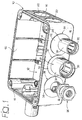
- a box for electric material which can be used as a pull box or for containing electric or electronic equipment of various nature in domestic or industrial electric installations.
- the box 10 comprises a bottom wall 12 and four lateral walls 16 and has an upper opening in correspondence of which is intended to be fixed a cover (not shown).
- the lateral walls 16 are formed non-though circular notches 18 which define lines of preferential breaking which permit to form through apertures 22 by removing the discs 20 surrounded by the notches 18.
- the box 10 may have no notches 18 and in this case the through holes 22 should be formed with a drilling apparatus of known type.
- the lateral walls 16 could be already provided with holes and could have caps formed with the same sealing system as the couplings and the couplings could be inserted in the desired holes after having removed the caps.
- a liquid-tight coupling according to the present invention.
- this coupling is adapted to be mounted on boxes of various type and does not require a particular configuration of the box.
- the only requirement for fitting the coupling 24 on any commercially available box is the existence of a through aperture 22 with suitable dimensions.
- the coupling 24 has a monolithic body of injection moulded plastic material in which are defined an attachment section 26 and a coupling section 28.
- the couplings according to the present invention form a family of articles which differ from each other for the shape and the dimensions of the coupling section 28, whereas the attachment section 26 is the same for all the couplings of the same family. It is then possible to obtain different families of articles by varying the dimensions of the attachment section 26.
- the coupling section 28 has a shape which depends on the type of element which must be connected to the box 10. In the most common cases, the coupling 24 is used for connecting to the box 10 smooth or corrugated conduits, smooth or spiral flexible sheaths or electric cables provided with insulating sheath. In figure 1 are shown the typical configurations of the coupling sections 28 for the connection of either insulated cables or conduits and sheaths. When an electric cable provided with an insulating sheath must be connected to the box 10, the coupling section has simply the shape of a threaded hole 34, with metric or PG thread, adapted to receive a clamping device per se known.
- the coupling section 28 When the coupling 24 serves for connecting to the box 10 a protection element formed by a conduit or by a sheath (smooth, with spiral grooves or corrugated) the coupling section 28 has a tubular portion 30, preferably provided with a seat 32 adapted to receive a seal of the type disclosed in European patent No. 515325 of the same Applicant, adapted to provide both mechanical connection and liquid-tightness on the surface of conduits both smooth and corrugated.
- the coupling section 28 could also be formed in any other way adapted to guarantee the mechanical connection, preferably liquid-tight, between the coupling 24 and the element to be connected to the box 10.
- the coupling section 28 could be formed as disclosed in European patent No. 568032 of the same Applicant.
- the principle on which the invention is based could also be used for manufacturing a cap for the fluid-tight closure of an aperture.
- the coupling section is substituted by a closed wall.
- the coupling portion 28 both when it is formed by a tubular portion and in the case in which it is formed by a threaded hole, can be coaxial or eccentric with respect to the attachment section 26.
- the eccentricity of the coupling portion 28 with respect to the attachment portion 26 permits to maintain conduits with different diameters at the same distance from a wall.
- the attachment section 26 of the coupling 24 has a tubular portion 38 with an external surface 40 having a diameter such that it engages with small clearance the aperture 22 of the wall 16.
- the tubular portion 38 On the tubular portion 38 are formed two or more teeth 42 (only one of which is visible in figure 3) projecting outwardly from the surface 40 and elastically deformable in a radial direction.
- Each tooth 42 has a stop surface 44 directed in a radial direction and an inclined surface 46 adapted to cooperate with the edge of the aperture 22 for permitting the radial deformation of the tooth 42 during insertion of the tubular portion 40 in the aperture 22.
- the radial deformability of each tooth 42 is obtained by means of three through cuts formed in the tubular portion 38 and which extend along three sides of the tooth 42. Two of such cuts are directed in an axial direction and are indicated at 48 in figure 2 and the third one is directed in a tangential direction and is indicated at 50 in figure 3.
- the coupling 24 has an integral disc-shaped portion 52 forming a dividing wall between the attachment section 26 and the coupling section 28.
- the disc-shaped portion 52 has a bearing surface 54 which extends outwardly in a radial direction with respect to the tubular portion 40.
- a step 56 having a cylindrical surface 58 with a diameter greater than the outer diameter of the tubular portion 38 and a radial abutment surface 60.
- a seal 62 of elastically deformable material is placed in correspondence with the bearing surface 54.
- the seal 62 has an annular shape with an inner diameter about equal to the diameter of the surface 58.
- the transversal cross section of the seal 62 in undeformed conditions is circular.
- the seal 62 is intended to be compressed axially between the bearing surface 54 and the external surface 64 of the wall 16. It is important that the seal 62 is formed of a material with is sufficiently yielding in order to mount coupling without need for an excessive force and which, on the other hand, is sufficiently rigid to maintain a sealing contact with the surfaces 54 and 64. Tests carried out by the Applicant have shown that the material forming the seal 62 should have a hardness comprised between 10 and 30 shore A.
- the seal 62 can be formed separately from the coupling 22 and mounted thereon or could be formed directly on the coupling, for example by the deposition of thermofusible material (hot melt) or of materials belonging to the family of mono or bi-component polyurethanes.
- the distance in axial direction between the seal 62 and the stop surface 44 of the teeth 42, indicated d1 is less than the minimum thickness of the wall 16 to which the coupling 24 is intended to be connected.
- the distance in axial direction between the abutment surface 60 and the stop surface 44, indicated d2, on the contrary represents the maximum thickness of the wall 16.
- Figures 4 and 5 show the coupling mounted on a wall 16 with minimum thickness t min and on a wall 16 with maximum thickness t max .
- the seal 62 is axially compressed with respect to the undeformed condition and applies an elastic force on the walls 54 and 64, which guarantee an effective liquids-tightness.
- An important advantage of the coupling according to the present invention is that it is adapted to be coupled with any wall having a thickness comprised between t min and t max .
- the family of couplings intended to be mounted in holes with a diameter of 32 mm is' adapted for walls with a thickness comprised between 2,2 and 2,8 mm.
- the coupling according to the invention does not require any particular configuration of the attachment zone of the wall 16.
- the coupling 2 can be mounted on any wall 16 having simply a hole 22 with a diameter about equal to the diameter of the tubular portion 40 and any thickness comprised between the minimum and maximum limit. Therefore, the coupling according to the present invention can be used in combination with boxes for electric material coming from different manufactures and permits an effective protection against the entry of liquids or humidity independently of the manufacturing tolerances of the boxes.
- the coupling according to the present invention is mounted with a simple insertion thereof in the hole 22 and permits to reduce the installation time with respect to the couplings which require tightening of threaded elements or the like.
- the coupling 24 in addition can be easily removed from the box simply by acting manually or using the point of a screwdriver on the teeth 42 from within the box and extracting the tubular portion 38 from the hole 22.
Landscapes
- Engineering & Computer Science (AREA)
- Architecture (AREA)
- Civil Engineering (AREA)
- Structural Engineering (AREA)
- Connection Or Junction Boxes (AREA)
- Connection Of Plates (AREA)
- Insulating Bodies (AREA)
Claims (6)
- Flüssigkeitsdichte Kupplung, insbesondere für Gehäuse für elektrische Installation, umfassend ein Befestigungssegment (26) zum Einsetzen der Kupplung (24) in ein Loch (22) einer Wand (16) und ein Kupplungssegment (28), das mit Mitteln zum Anschluß an ein Schutzelement einer elektrischen Anlage versehen ist, wobei das Befestigungssegment (26) umfaßt:dadurch gekennzeichnet, daßeinen rohrförmigen Abschnitt (38), der mit Rastverbindungsmitteln (42) versehen ist, die zumindest eine von der Außenfläche (40) des rohrförmigen Abschnitts (38) vorspringende Anschlagfläche (44) zum Angriff an einer Innenfläche der Wand (16) aufweisen,eine Lagerfläche (54), die von der Anschlagfläche (44) axial beabstandet und außerhalb des rohrförmigen Abschnitts (38) plaziert ist, undeine axial verformbare Ringdichtung (62), die in Übereinstimmung mit der Lagerfläche (54) angeordnet ist, wobei der Abstand (dl) zwischen der Dichtung (62) und der Anschlagfläche (44) im undeformierten Zustand geringer ist als die Minimaldicke (tmin) einer Wand (16), an die die Kupplung (24) angeschlossen werden soll,
die Dichtung (62) im undeformierten Zustand einen kreisförmigen Querschnitt aufweist und daß die Dichtung (62) aus einem Material mit einer Shore-A-Härte zwischen 10 und 30 besteht. - Kupplung gemäß Anspruch 1, dadurch gekennzeichnet, daß am Unterteil der Lagerfläche (54) eine Stufe (56) mit einer Auflagerfläche (60) ausgebildet ist, die von der Anschlagfläche (44) in axialer Richtung um eine Größe (d2) beabstandet ist, die im wesentlichen gleich der Maximaldicke (tmax) der Wand (16) ist, an die die Kupplung (24) angeschlossen werden soll.
- Kupplung gemäß Anspruch 1, dadurch gekennzeichnet, daß die Dichtung (62) durch Ablagerung eines thermoschmelzbaren Werkstoffs oder Schaumstoffs auf der Kupplung (24) geformt wird.
- Kupplung gemäß Anspruch 1, dadurch gekennzeichnet, daß die Dichtung (62) durch ein separates Bauteil gebildet ist, das auf der Kupplung (24) aufsitzt.
- Kupplung gemäß Anspruch 1, dadurch gekennzeichnet, daß die Rastverbindungsmittel zumindest ein Paar elastisch verformbarer Zähne (42) umfassen, die durch Durchstiche (48, 50) einstückig in dem rohrförmigen Abschnitt (38) eingeformt sind.
- Flüssigkeitsdichte Kappe, insbesondere für Gehäuse für elektrische Installation, umfassend ein zum Einsetzen in eine Durchgangsöffnung (22) einer Wand (16) bestimmtes Befestigungssegment (26),
dadurch gekennzeichnet, daß
das Befestigungssegment (26) umfaßt:wobei der Abstand (d1) zwischen der Dichtung (62) und der Anschlagfläche (44) im undeformierten Zustand geringer ist als die Minimaldicke (tmin) der Wand (16),einen rohrförmigen Abschnitt (38), der mit Rastverbindungsmitteln (42) versehen ist, die zumindest eine von der Außenfläche (40) des rohrförmigen Abschnitts (38) vorspringende Anschlagfläche (44) zum Angriff an einer Innenfläche der Wand (16) aufweisen,eine Lagerfläche (54), die von der Anschlagfläche (44) axial beabstandet und außerhalb des rohrförmigen Abschnitts (38) angeordnet ist,eine axial verformbare Ringdichtung (62), die in Übereinstimmung mit der Lagerfläche (54) angeordnet ist,
wobei die Dichtung (62) im undeformierten Zustand einen kreisförmigen Querschnitt aufweist und wobei die Dichtung (62) aus einen Material mit einer Shore-A-Härte zwischen 10 und 30 besteht.
Priority Applications (3)
| Application Number | Priority Date | Filing Date | Title |
|---|---|---|---|
| DE1998600799 DE69800799T2 (de) | 1998-03-27 | 1998-03-27 | Flüssigkeitdichte Kupplung für Gehäuse für elektrische Installation |
| ES98830186T ES2156434T3 (es) | 1998-03-27 | 1998-03-27 | Acoplamiento estanco a los liquidos para cajas para material electrico. |
| EP19980830186 EP0961375B1 (de) | 1998-03-27 | 1998-03-27 | Flüssigkeitdichte Kupplung für Gehäuse für elektrische Installation |
Applications Claiming Priority (1)
| Application Number | Priority Date | Filing Date | Title |
|---|---|---|---|
| EP19980830186 EP0961375B1 (de) | 1998-03-27 | 1998-03-27 | Flüssigkeitdichte Kupplung für Gehäuse für elektrische Installation |
Publications (2)
| Publication Number | Publication Date |
|---|---|
| EP0961375A1 EP0961375A1 (de) | 1999-12-01 |
| EP0961375B1 true EP0961375B1 (de) | 2001-05-16 |
Family
ID=8236595
Family Applications (1)
| Application Number | Title | Priority Date | Filing Date |
|---|---|---|---|
| EP19980830186 Expired - Lifetime EP0961375B1 (de) | 1998-03-27 | 1998-03-27 | Flüssigkeitdichte Kupplung für Gehäuse für elektrische Installation |
Country Status (3)
| Country | Link |
|---|---|
| EP (1) | EP0961375B1 (de) |
| DE (1) | DE69800799T2 (de) |
| ES (1) | ES2156434T3 (de) |
Families Citing this family (2)
| Publication number | Priority date | Publication date | Assignee | Title |
|---|---|---|---|---|
| DE69921499D1 (de) * | 1999-12-28 | 2004-12-02 | Bertoldo & C Srl | Flüssigkeitsdichte Kupplung |
| TWI744129B (zh) * | 2020-12-09 | 2021-10-21 | 英業達股份有限公司 | 多向夾線裝置 |
Family Cites Families (6)
| Publication number | Priority date | Publication date | Assignee | Title |
|---|---|---|---|---|
| US4090029A (en) * | 1976-04-15 | 1978-05-16 | General Signal Corporation | Liquid tight connector with improved ground conductivity |
| US4468535A (en) * | 1981-12-29 | 1984-08-28 | Thomas & Betts Corporation | Snap-on liquid tight connector for flexible metal conduit |
| EP0106001A1 (de) * | 1982-10-13 | 1984-04-25 | GebràDer Sulzer Aktiengesellschaft | Verfahren zum Anschliessen von Kabelschläuchen an einen Schaltkasten z.B. einer Webmaschine und Einrichtung zur Durchführung des Verfahrens |
| JPH03124741A (ja) * | 1989-09-29 | 1991-05-28 | Dow Chem Co:The | 軟質ポリウレタンフォームおよびその製造方法 |
| US5068496A (en) * | 1990-10-31 | 1991-11-26 | Hubbell Incorporated | Snap-in connector |
| JPH08241701A (ja) * | 1995-03-01 | 1996-09-17 | Amp Japan Ltd | バッテリー組立体及びその製造方法 |
-
1998
- 1998-03-27 EP EP19980830186 patent/EP0961375B1/de not_active Expired - Lifetime
- 1998-03-27 DE DE1998600799 patent/DE69800799T2/de not_active Expired - Lifetime
- 1998-03-27 ES ES98830186T patent/ES2156434T3/es not_active Expired - Lifetime
Also Published As
| Publication number | Publication date |
|---|---|
| DE69800799D1 (de) | 2001-06-21 |
| ES2156434T3 (es) | 2001-06-16 |
| EP0961375A1 (de) | 1999-12-01 |
| DE69800799T2 (de) | 2001-10-04 |
Similar Documents
| Publication | Publication Date | Title |
|---|---|---|
| EP0515325B1 (de) | Dichtung für eine elektrische Leitungsschutzrohrkupplung und Kupplung mit dieser Dichtung | |
| US7582836B2 (en) | Core for a cable entry device | |
| US5204499A (en) | Snap-in connector with integral spring | |
| US5422437A (en) | Electrical connector assembly | |
| US5912431A (en) | Snap-in locknut adapter for connectors | |
| US7579556B2 (en) | Cable entry device comprising means for adjustment | |
| JPH077837A (ja) | ケーブルグランド | |
| US7579557B2 (en) | Cable entry device for easy installation | |
| CA2070262A1 (en) | Device for sealing the end of a heat-shrunk sleeve | |
| EP0779681B1 (de) | Anschlusskasten aus Plastik | |
| CA2094789C (en) | Cable connector clamp | |
| EP0961375B1 (de) | Flüssigkeitdichte Kupplung für Gehäuse für elektrische Installation | |
| US20020033269A1 (en) | Electrical tubing assembly with hermetically sealed ends | |
| EP1653583B1 (de) | Verbindung für gewickelte Schutzhülle | |
| EP0961376B1 (de) | Kupplung mit exzentrischen Teilen, insbesondere für Gehäuse zur elektrischen Installation | |
| EP0811127B1 (de) | Rohrkupplung und verfahren zum verbinden eines rohres an einem verbindungsstück | |
| EP0959543B1 (de) | Gehäuse für elektrische Installation mit Befestigungsvorrichtung für den Deckel und Wandbefestigung | |
| EP1113553B1 (de) | Flüssigkeitsdichte Kupplung | |
| US4496792A (en) | Electrical conduit with vapor barrier device | |
| EP0961143A2 (de) | Einstückige Lichtleiter-Kopplungsvorrichtung | |
| US20250385463A1 (en) | Mobile industrial socket/plug with improved gasket of the cable passage | |
| ITMI970661A1 (it) | Ingresso di cavo o diconduttura a montaggio rapido | |
| WO1992013378A1 (en) | Connector assembly for connecting flexible metallic conduit to an electrical box |
Legal Events
| Date | Code | Title | Description |
|---|---|---|---|
| PUAI | Public reference made under article 153(3) epc to a published international application that has entered the european phase |
Free format text: ORIGINAL CODE: 0009012 |
|
| 17P | Request for examination filed |
Effective date: 19981113 |
|
| AK | Designated contracting states |
Kind code of ref document: A1 Designated state(s): AT BE CH DE DK ES FI FR GB GR IE IT LI LU MC NL PT SE |
|
| AX | Request for extension of the european patent |
Free format text: AL;LT;LV;MK;RO;SI |
|
| AKX | Designation fees paid | ||
| GRAG | Despatch of communication of intention to grant |
Free format text: ORIGINAL CODE: EPIDOS AGRA |
|
| RBV | Designated contracting states (corrected) |
Designated state(s): AT BE CH DE DK ES LI |
|
| RBV | Designated contracting states (corrected) |
Designated state(s): DE ES FR GB IT NL |
|
| GRAG | Despatch of communication of intention to grant |
Free format text: ORIGINAL CODE: EPIDOS AGRA |
|
| GRAH | Despatch of communication of intention to grant a patent |
Free format text: ORIGINAL CODE: EPIDOS IGRA |
|
| REG | Reference to a national code |
Ref country code: DE Ref legal event code: 8566 |
|
| GRAH | Despatch of communication of intention to grant a patent |
Free format text: ORIGINAL CODE: EPIDOS IGRA |
|
| GRAA | (expected) grant |
Free format text: ORIGINAL CODE: 0009210 |
|
| REG | Reference to a national code |
Ref country code: DE Ref legal event code: 8570 |
|
| AK | Designated contracting states |
Kind code of ref document: B1 Designated state(s): DE ES FR GB IT NL |
|
| ITF | It: translation for a ep patent filed | ||
| REG | Reference to a national code |
Ref country code: ES Ref legal event code: FG2A Ref document number: 2156434 Country of ref document: ES Kind code of ref document: T3 |
|
| REF | Corresponds to: |
Ref document number: 69800799 Country of ref document: DE Date of ref document: 20010621 |
|
| ET | Fr: translation filed | ||
| REG | Reference to a national code |
Ref country code: GB Ref legal event code: IF02 |
|
| PLBE | No opposition filed within time limit |
Free format text: ORIGINAL CODE: 0009261 |
|
| STAA | Information on the status of an ep patent application or granted ep patent |
Free format text: STATUS: NO OPPOSITION FILED WITHIN TIME LIMIT |
|
| 26N | No opposition filed | ||
| PGFP | Annual fee paid to national office [announced via postgrant information from national office to epo] |
Ref country code: NL Payment date: 20070304 Year of fee payment: 10 |
|
| PGFP | Annual fee paid to national office [announced via postgrant information from national office to epo] |
Ref country code: ES Payment date: 20080418 Year of fee payment: 11 Ref country code: DE Payment date: 20080407 Year of fee payment: 11 |
|
| PG25 | Lapsed in a contracting state [announced via postgrant information from national office to epo] |
Ref country code: NL Free format text: LAPSE BECAUSE OF NON-PAYMENT OF DUE FEES Effective date: 20081001 |
|
| NLV4 | Nl: lapsed or anulled due to non-payment of the annual fee |
Effective date: 20081001 |
|
| PGFP | Annual fee paid to national office [announced via postgrant information from national office to epo] |
Ref country code: GB Payment date: 20080402 Year of fee payment: 11 |
|
| PG25 | Lapsed in a contracting state [announced via postgrant information from national office to epo] |
Ref country code: DE Free format text: LAPSE BECAUSE OF THE APPLICANT RENOUNCES Effective date: 20090223 |
|
| GBPC | Gb: european patent ceased through non-payment of renewal fee |
Effective date: 20090327 |
|
| PG25 | Lapsed in a contracting state [announced via postgrant information from national office to epo] |
Ref country code: GB Free format text: LAPSE BECAUSE OF NON-PAYMENT OF DUE FEES Effective date: 20090327 |
|
| REG | Reference to a national code |
Ref country code: ES Ref legal event code: FD2A Effective date: 20090328 |
|
| PG25 | Lapsed in a contracting state [announced via postgrant information from national office to epo] |
Ref country code: ES Free format text: LAPSE BECAUSE OF NON-PAYMENT OF DUE FEES Effective date: 20090328 |
|
| PGFP | Annual fee paid to national office [announced via postgrant information from national office to epo] |
Ref country code: FR Payment date: 20120319 Year of fee payment: 15 |
|
| PGFP | Annual fee paid to national office [announced via postgrant information from national office to epo] |
Ref country code: IT Payment date: 20120305 Year of fee payment: 15 |
|
| REG | Reference to a national code |
Ref country code: FR Ref legal event code: ST Effective date: 20131129 |
|
| PG25 | Lapsed in a contracting state [announced via postgrant information from national office to epo] |
Ref country code: FR Free format text: LAPSE BECAUSE OF NON-PAYMENT OF DUE FEES Effective date: 20130402 |
|
| PG25 | Lapsed in a contracting state [announced via postgrant information from national office to epo] |
Ref country code: IT Free format text: LAPSE BECAUSE OF NON-PAYMENT OF DUE FEES Effective date: 20140327 |