EP0961369B1 - Mehrfachsteckdose - Google Patents
Mehrfachsteckdose Download PDFInfo
- Publication number
- EP0961369B1 EP0961369B1 EP99401234A EP99401234A EP0961369B1 EP 0961369 B1 EP0961369 B1 EP 0961369B1 EP 99401234 A EP99401234 A EP 99401234A EP 99401234 A EP99401234 A EP 99401234A EP 0961369 B1 EP0961369 B1 EP 0961369B1
- Authority
- EP
- European Patent Office
- Prior art keywords
- base
- socket
- power outlet
- outlet according
- socket power
- Prior art date
- Legal status (The legal status is an assumption and is not a legal conclusion. Google has not performed a legal analysis and makes no representation as to the accuracy of the status listed.)
- Expired - Lifetime
Links
- 238000000465 moulding Methods 0.000 claims description 12
- 238000000638 solvent extraction Methods 0.000 claims description 7
- 230000000295 complement effect Effects 0.000 claims description 6
- 230000000694 effects Effects 0.000 claims 1
- BASFCYQUMIYNBI-UHFFFAOYSA-N platinum Chemical compound [Pt] BASFCYQUMIYNBI-UHFFFAOYSA-N 0.000 description 10
- 230000008901 benefit Effects 0.000 description 7
- 229910052697 platinum Inorganic materials 0.000 description 6
- 238000012423 maintenance Methods 0.000 description 2
- 238000000034 method Methods 0.000 description 2
- 150000003057 platinum Chemical class 0.000 description 2
- 230000006978 adaptation Effects 0.000 description 1
- 239000011324 bead Substances 0.000 description 1
- 239000004020 conductor Substances 0.000 description 1
- 238000005520 cutting process Methods 0.000 description 1
- 238000009826 distribution Methods 0.000 description 1
- 230000009189 diving Effects 0.000 description 1
- 230000002349 favourable effect Effects 0.000 description 1
- 238000003780 insertion Methods 0.000 description 1
- 230000037431 insertion Effects 0.000 description 1
- 238000009434 installation Methods 0.000 description 1
- 238000009413 insulation Methods 0.000 description 1
- 238000004519 manufacturing process Methods 0.000 description 1
- 229910052751 metal Inorganic materials 0.000 description 1
- 239000002184 metal Substances 0.000 description 1
- NJPPVKZQTLUDBO-UHFFFAOYSA-N novaluron Chemical compound C1=C(Cl)C(OC(F)(F)C(OC(F)(F)F)F)=CC=C1NC(=O)NC(=O)C1=C(F)C=CC=C1F NJPPVKZQTLUDBO-UHFFFAOYSA-N 0.000 description 1
- 238000006467 substitution reaction Methods 0.000 description 1
Images
Classifications
-
- H—ELECTRICITY
- H01—ELECTRIC ELEMENTS
- H01R—ELECTRICALLY-CONDUCTIVE CONNECTIONS; STRUCTURAL ASSOCIATIONS OF A PLURALITY OF MUTUALLY-INSULATED ELECTRICAL CONNECTING ELEMENTS; COUPLING DEVICES; CURRENT COLLECTORS
- H01R25/00—Coupling parts adapted for simultaneous co-operation with two or more identical counterparts, e.g. for distributing energy to two or more circuits
- H01R25/003—Coupling parts adapted for simultaneous co-operation with two or more identical counterparts, e.g. for distributing energy to two or more circuits the coupling part being secured only to wires or cables
Definitions
- the present invention relates generally to the pedestals of power socket.
- All of these power socket sockets include at least two power outlets, each of which is suitable for receiving a plug complementary socket outlet, and which, in practice, form the most often each a well in which such an outlet plug must to be engaged.
- the present invention aims more particularly at those pedestals of outlets in which power outlets are distributed on two side faces of their housing opposite back to back one to the other, each of these lateral faces thus comprising at least one such position socket outlet.
- the housing is formed of two shells of similar dimensions, which, by their bottom, form the lateral faces having at least one outlet station, and which are assembled one to the other following a junction plane substantially parallel to these faces side, forming between them a housing in which intervene the necessary contact elements, with, in one piece with one and / or the other of these shells, elements of partitioning, which, fragmenting into compartments this housing, form holding means for the contact elements.
- junction plane of the two shells inevitably crosses the front of the case, penalizing more or less the aesthetics of it.
- the housing of these comprises, of a a base, which carries the contact elements, and which, in practice, is reduced to a substantially flat plate, and, on the other hand, a hood, too commonly called housing, which, in general bell shape although of overall parallelepiped contour, covers the base and the elements of contact, and of which two opposite lateral faces each carry at least one outlet station.
- the housing comprises, on the one hand, a base, which carries the positions of current, and which between them forms a dwelling in which the corresponding contact elements, and, on the other hand, a cover, which attached to the base, closes the housing formed by it, the base comprising, in one piece, a platinum which receives the elements of contact, and two cheeks, which each forming at least part the two side faces of the housing, each carry at least one post socket outlet.
- the present invention generally relates to a provision to avoid the above disadvantages and leading to besides other advantages.
- a socket socket multi-socket of the kind comprising, on each of two lateral faces of its housing opposite back to back to each other, at least one position taking current clean to receive a complementary socket plug, this housing comprising, on the one hand, a base, which carries the positions of current, and which between them forms a dwelling in which the corresponding contact elements, and, on the other hand, a cover, which attached to the base, closes the housing formed by it, the base having, itself, a plate, which receives the contact elements, and two cheeks, which are intended to train each respectively for at least part the two side faces of the housing, each carry at least one post socket outlet, this plug socket outlet socket being of a generally characterized in that the two cheeks of the base are each respectively hinged to the plate thereof by two hinges parallel.
- the cheeks forming the socket positions are, according to the invention, each articulated to the plate of the base between a initial molding position, for which they extend one and the other overall flat with this board, and a final mounting position, for which they are both erected substantially perpendicular to this platinum.
- the base of the power socket outlet socket according to the invention is advantageously easy transport and distribution, and it is advantageous for easy installation, by simple stacking, both contact elements as possible safety cassettes, which is favorable to the possible automation of the corresponding operations, benefit from cost reduction.
- the invention when the following socket outlet socket the invention is a fixed base, the fact that the cheeks of its base are articulated and so can again be deployed flat if desired gives advantageously a maximum access to the plate of this base, which is nature to facilitate the attachment of this base to any support and the wiring of the contact elements that it carries.
- the front face of the housing of the base of power socket outlet according to the invention is advantageously devoid of any plan of junction, for the benefit of its aesthetics and a modulation possible of this one.
- this cover having no other technical function to ensure that that of closing the base, it is advantageously possible, if to change its appearance according to the needs of the market, and thus to to follow at best the desires of the potential customers interested.
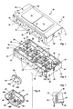
- the base of socket power strip 10 comprises, on each of two side faces 11 of its housing 12 opposite back to back to one another, at least one outlet station 13 capable of receiving a plug complementary current not shown in these figures.
- the housing 12 presents itself in the general form of a globally parallelepipedal plate, and the side faces 1 1 on which intervene the positions of socket 13 belong to his slice.
- these lateral faces 11 are the longitudinal faces of the housing 12.
- the housing 12 has a lower face 15 and a face superior 16.
- the base socket Power strip 10 is, for example, a power strip unit.
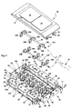
- a mobile power socket which, like schematized in broken lines in Figure 2, must be equipped with a cord 18 for its service, that is to say an electrical cable comprising the number of conductors 19 required and provided at its end with a plug current not shown.
- one of the transverse faces 14 comprises, in the usual manner, a recess 20, and this is, for example, and such than represented, a notch.
- this number is equal to three.
- the pickup stations current 13 which are all identical to each other, meet the standard next :
- they each comprise two holes 22A, 22B, for the passage of the pins of the corresponding socket plug.
- the sidewall 25 of such a well 23 a in cross-section, an elongated contour, with intermediate flats and rounded ends.
- sockets 13 can raise another standard.
- they may include a ground contact, such as pin Or other.
- the socket 13 are elongate, flat, along the side faces 11 which the carry.
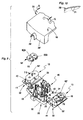
- the housing 12 of the socket outlet power strip 10 comprises, on the whole, on the one hand, a base 26, which, according to the methods described in more detail subsequently, carries the outlets 13, and between them, forms a housing 28 in which the contact elements 29A intervene, 29B corresponding, and, secondly, a lid 30, which, reported on the base 26, according to terms also described in more detail subsequently closes the housing 28 formed by it, this base 26 comprising, on the one hand, a plate 31, which receives the elements of contact 29A, 29B, and, secondly, two cheeks 32, which, intended to form each respectively at least partly the two lateral faces 11 of the housing 12, each carry at least one outlet station 13, and, in In this case, three power outlets 13.
- the two cheeks 32 of the base 26 are each respectively hinged to the plate 31 thereof by two hinges 33 parallel.
- the cheeks 32 are thus each articulated to the plate 31 of the base 26 between an initial molding position, which is the one shown in Figure 2, and for which they both extend globally to plate with this plate 31, and a final mounting position, which is the one shown in Figures 1 and 6, for which they are both erected substantially perpendicularly to this plate 31.
- the cheeks 32 are each in one piece with the base 26, the molding forming assembly one and the same room.
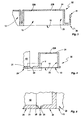
- the hinge 33 articulating a cheek 32 to the base 26, and, more specifically, to the plate 31 thereof, extends continuously throughout the corresponding hinge line, and as it is best seen in FIGS. 4 and 5, it is formed by a zone of lesser thickness.
- this hinge 33 extends level with the outer surface of the plate 31 and the outer surface of the cheeks 32, in continuity with these, and the slices corresponding to this plate 31 and these cheeks 32 are each beveled by a chamfer 35 which extends to 45 °, so that for the initial molding position of the set, these slices together form a dihedron whose angle is substantially equal to 90 °.
- each of the sockets 13 form recessed a well 23 on the outer surface of the cheek 32 which carries it, and this well 23 extends therefore protruding on the inner surface thereof.
- the cheeks 32 do not form each respectively that a part of the side faces 11 of the housing 12.
- the walls 36 forming the transverse faces 14 of the housing 12 therefore each have, at their ends, along the longitudinal edges of the plate 31, returns 37, which complement, in correspondence, the faces 11 side of this housing 12.
- the free angle of returns 37 of these walls 36 is cut by a step 38.
- each cheeks 32 and the base 26 latching means 40 adapted to ensure maintaining such a cheek 32 in the final mounting position.
- these latching means 40 comprise, on a flange 32, at least one latching lug 41, which shaped hook, is elastically deformable, and on the base 26, a latching catch 42, with which such a latching lug 41 is adapted to come into engagement.
- the latching lug 41 is substantially perpendicular to the cheek 32, and it protrudes on the inner surface thereof.
- each of the cheeks 32 there is a snap tab 41 at each end of each of the cheeks 32, along each of the transverse edges thereof.
- the corresponding latching notches 42 are formed by the slice of flanges 43 which, coming from the free edge of the returns 37 of the walls 36 forming the transverse faces 14 of the housing 12, extend towards the interior, substantially parallel to these walls 36.
- partitioning elements 46 which can be configurations very diverse, and whose realization falls within the skill of the art, will not be described in detail here.
- compartments 45A, 45B are arranged in two alignments, parallel to the cheeks 32, and they intervene alternately at within each of these alignments.
- the contact elements 29A, 298 are alveoli, and they are grouped by polarity, the elements of contact 29A jointly belonging to a single contact piece 47A, and the contact elements 29B belonging, themselves, jointly, to one and the same contact piece 47B.
- these contact pieces 47A, 47B which each result from the cutting and folding of the same metal blank, are identical to each other.
- these contact pieces 47A, 47B are arranged in facing relation, the contact elements 29A extending for example down to the contact piece 47A while the contact elements 29B extend upwardly for the contact piece 478, and they are longitudinally offset from one another, the contact elements 29A of the contact piece 47A being arranged in the compartments 45A of this housing 28 while the contact elements 29B of the room of contact 478 are arranged in the compartments 45B of this housing 28.
- the cover 30 extends, in plan, over the entire surface of the base 26.
- the latching means 50 implemented comprise, on the lid 30, at least one pin 51, which makes protruding on the lower surface of this cover 30, and, in correspondence, on the base 26, at least one barrel 52, which projects on the plate 31 of this base 26, substantially perpendicular to this plate 31, and which, presenting for this purpose a bore 53, is adapted to receive such a pin 51.
- the plate 31 comprises, in correspondence, four drums 52.
- the lid 30 is generally flat.
- Such a security cassette 58 is well known by itself, and not falling within the scope of the present invention, it will not be described here.
- the security cassette 58 present, back to back, on its edge, two notches 61.
- these guide means 62 have two flanges 63, which frame the compartments 45A, 45B corresponding, extending parallel to each other, perpendicularly to the plate 31 of the base 26 and perpendicularly to the cheeks 32.
- the guiding means 62 comprise, in addition, a pin 64, which, projecting on the plate 31 of the base 26, extends between the two compartments 45A, 45B corresponding.
- the guiding means 62 thus formed make protrusion on the plate 31 of the base 26, substantially perpendicular to this, to facilitate the molding of this base 26, as the elements of partitioning 46.
- the corresponding operations are done in this order, but if desired, it can be reversed.
- security cassettes 58 are also provided. place, if desired.
- the positioning of the contact pieces 47A, 47B and that of the security cassettes 58 are advantageously by simple stacking.
- the faces transverse 14 of the housing 12 are formed by fallen edges 36 'of the cover 30 instead of being formed by walls 36 coming from the plate 31 of the base 26.
- each of the sockets 13 projecting from the back of each of the sockets 13, that is to say projecting on the bottom 24 of the well 23 that forms such a socket station 13, a pin 62 ' adapted to receive, with a slight tightening, a security cassette 58 ', the latter presenting, then, to do this, between its holes 60A, 60B, a recess 66.
- complementary means are provided, such as for example ribs, to prevent rotation.
- each of the cheeks 32 and the cover 30, engagement means 70, 71 to reinforce the maintenance of these cheeks 32 in final mounting position after the establishment of this lid 30 and thus allow them to resist more surely to a possible urge of pushing or pulling.
- these engagement means 70, 71 comprise, at each of the positions of socket 13 of such plays 32, a tab 70, which protrudes laterally on the corresponding well 23, substantially level with the bottom 24 thereof, and, in correspondence, on the cover 30, two ribs 71, which project on the inner surface of this cover 30, and which, during the establishment of it, come to frame a such tab 70.
- the lid 30 is provided on the surface with decorative motifs different from the previous ones.
- the plug socket outlet socket according to the invention is a mobile pedestal, of the type commonly referred to as multi-socket blocks, it can just as well be a fixed base or an adapter.
Landscapes
- Connector Housings Or Holding Contact Members (AREA)
- Polishing Bodies And Polishing Tools (AREA)
- Iron Core Of Rotating Electric Machines (AREA)
- Fixed Capacitors And Capacitor Manufacturing Machines (AREA)
- Insulators (AREA)
- Insulated Conductors (AREA)
- Piezo-Electric Or Mechanical Vibrators, Or Delay Or Filter Circuits (AREA)
- External Artificial Organs (AREA)
- Fats And Perfumes (AREA)
- Centrifugal Separators (AREA)
- Forklifts And Lifting Vehicles (AREA)
- Vehicle Step Arrangements And Article Storage (AREA)
Claims (20)
- Mehrfachsteckdosensockel, welcher auf jeder von zwei Seitenflächen (11) seines Gehäuses (12), die sich Rücken an Rücken gegenüberliegen, zumindest eine Steckdose (13) aufweist, welche geeignet ist, einen komplementären Stecker aufzunehmen, wobei das Gehäuse einerseits eine Basis (26) aufweist, die die Steckdosen (13) trägt und die zwischen diesen einen Raum (28) bildet, in dem die korrespondierenden Kontaktelemente (29A, 29B) liegen und andererseits einen Deckel (30) aufweist, der, auf der Basis (26) angebracht, den von dieser gebildeten Raum (28) verschließt, wobei die Basis (26) ihrerseits einerseits eine Platte (31), welche die Kontaktelemente (29A, 29B) aufnimmt, und andererseits zwei Seitenwände (32) aufweist, die dazu bestimmt sind jeweils zumindest einen Teil der beiden Seitenflächen (11) des Gehäuses (12) zu bilden, und die jede zumindest eine Steckdose (13) tragen,
dadurch gekennzeichnet, dass jede der zwei Seitenwände (32) der Basis (26) jeweils über zwei parallele Scharniere (33) gelenkig mit deren Platte (31) verbunden ist. - Mehrfachsteckdosensockel nach Anspruch 1,
dadurch gekennzeichnet, dass jede Seitenwand (32) einstückig mit der Basis (26) ausgebildet ist. - Mehrfachsteckdosensockel nach Anspruch 2,
dadurch gekennzeichnet, dass das Scharnier (33), welches eine Seitenwand (32) gelenkig mit der Basis (26) verbindet, von einem Bereich geringerer Dicke gebildet ist. - Mehrfachsteckdosensockel nach einem der Ansprüche 2 oder 3,
dadurch gekennzeichnet, dass sich das Scharnier (33), welches eine Seitenwand (32) gelenkig mit der Basis (26) verbindet, durchgehend entlang der entsprechenden Gelenkachse erstreckt. - Mehrfachsteckdosensockel nach einem der Ansprüche 1 bis 4,
dadurch gekennzeichnet, dass die Seitenwände (32) an der Platte (31) der Basis (26) gelenkig gelagert sind zwischen einer Gieß-Anfangsposition, in der sie sich beide im Wesentlichen flach mit dieser Platte (31) ausgerichtet erstrecken, und einer Montage-Endposition, in der sie beide im Wesentlichen in einem rechten Winkel zu dieser Platte (31) aufgerichtet sind. - Mehrfachsteckdosensockel nach Anspruch 5,
dadurch gekennzeichnet, dass zwischen jeder Seitenwand (32) und der Basis (26) Verrastmittel (40) vorgesehen sind, welche dazu geeignet sind, den Halt einer solchen Seitenwand (32) in der Montage-Endposition zu gewährleisten - Mehrfachsteckdosensockel nach Anspruch 6,
dadurch gekennzeichnet, dass die Verrastmittel (40) auf einer Seitenwand (32) zumindest eine Verrastlasche (41) aufweisen, die hakenförmig ausgebildet und elastisch verformbar ist, und auf der Basis (26) eine Rastkerbe (42) vorgesehen ist, wobei die Verrastlasche (41) geeignet ist, mit dieser in Eingriff zu gelangen. - Mehrfachsteckdosensockel nach Anspruch 7,
dadurch gekennzeichnet, dass die Verrastlasche (41) im Wesentlichen senkrecht zu der Seitenwand (32) ist. - Mehrfachsteckdosensockel nach einem der Ansprüche 7, 8,
dadurch gekennzeichnet, dass an jedem Ende jeder Seitenwand (32) eine Verrastlasche (41) vorgesehen ist. - Mehrfachsteckdosensockel nach einem der Ansprüche 5 bis 9,
dadurch gekennzeichnet, dass zwischen jeder Seitenwand (32) und dem Deckel (30) Eingriffsmittel (70, 71) vorgesehen sind. - Mehrfachsteckdosensockel nach einem der Ansprüche 1 bis 10,
dadurch gekennzeichnet, dass jede der Steckdosen (13) auf der äußeren Oberfläche der sie tragenden Seitenwand (32) als Ausnehmung einen Schacht (23) bildet. - Mehrfachsteckdosensockel nach den Ansprüchen 9 und 10 zusammengenommen,
dadurch gekennzeichnet, dass die Eingriffsmittel (70, 71) an jeder Steckdose (13) einer Seitenwand (32) eine seitlich über den entsprechenden Schacht (23) vorstehende Lasche (70) und dazu korrespondierend auf dem Deckel (30) zwei Rippen (71), die beim Einsetzen desselben eine solche Lasche (70) einrahmen, aufweisen. - Mehrfachsteckdosensockel nach einem der Ansprüche 1 bis 12,
dadurch gekennzeichnet, dass jeder der Steckdosen (13) eine Sicherheitskassette (58, 58') zugeordnet ist, welche geeignet ist, den Zugang zu den dazugehörigen Kontaktelementen (29A, 29B) zu kontrollieren. - Mehrfachsteckdosensockel nach Anspruch 13,
dadurch gekennzeichnet, dass auf der Basis (26) zwischen jeder Steckdose (13) und dem Raum (28), in dem die dazugehörigen Kontaktelemente (29A, 29B) liegen, Führungsmittel (62) vorgesehen sind, welche geeignet sind, eine Sicherheitskassette (58) aufzunehmen. - Mehrfachsteckdosensockel nach Anspruch 14,
dadurch gekennzeichnet, dass die Führungsmittel (62) im Wesentlichen senkrecht zu der Platte (31) der Basis (26) über diese vorstehen. - Mehrfachsteckdosensockel nach Anspruch 13,
dadurch gekennzeichnet, dass vorspringend auf der Rückseite jeder Steckdose (13) ein Element (62') vorgesehen ist, welches dazu geeignet ist, mit einer leichten Klemmung eine Sicherheitskassette (58') aufzunehmen. - Mehrfachsteckdosensockel nach einem der Ansprüche 1 bis 16,
dadurch gekennzeichnet, dass der Raum (28), in dem die Kontaktelemente (29A, 29B) liegen, von Trennelementen (46), welche über die Platte (31) der Basis (26) vorstehen, in Abteile (45A, 45B) unterteilt ist. - Mehrfachsteckdosensockel nach Anspruch 17,
dadurch gekennzeichnet, dass die Trennelemente (46) sich im Wesentlichen senkrecht zu der Platte (31) der Basis (26) erstrecken. - Mehrfachsteckdosensockel nach einem der Ansprüche 1 bis 18,
dadurch gekennzeichnet, dass zwischen dem Deckel (30) und der Basis (26) Verrastmittel (50) vorgesehen sind. - Mehrfachsteckdosensockel nach Anspruch 19,
dadurch gekennzeichnet, dass die Verrastmittel (50) auf dem Deckel (30) wenigstens ein vorspringendes Rastelement (51) aufweisen und auf der Basis (26) einen dazu korrespondierenden Hohlzylinder (52) aufweisen, welcher geeignet ist, ein solches Rastelement (51) aufzunehmen.
Applications Claiming Priority (2)
| Application Number | Priority Date | Filing Date | Title |
|---|---|---|---|
| FR9806613 | 1998-05-26 | ||
| FR9806613A FR2779277B1 (fr) | 1998-05-26 | 1998-05-26 | Socle de prise de courant multiprise |
Publications (2)
| Publication Number | Publication Date |
|---|---|
| EP0961369A1 EP0961369A1 (de) | 1999-12-01 |
| EP0961369B1 true EP0961369B1 (de) | 2005-02-16 |
Family
ID=9526718
Family Applications (1)
| Application Number | Title | Priority Date | Filing Date |
|---|---|---|---|
| EP99401234A Expired - Lifetime EP0961369B1 (de) | 1998-05-26 | 1999-05-21 | Mehrfachsteckdose |
Country Status (8)
| Country | Link |
|---|---|
| EP (1) | EP0961369B1 (de) |
| AT (1) | ATE289454T1 (de) |
| DE (1) | DE69923728T2 (de) |
| DK (1) | DK0961369T3 (de) |
| ES (1) | ES2237055T3 (de) |
| FR (1) | FR2779277B1 (de) |
| HU (1) | HU223238B1 (de) |
| PL (1) | PL192981B1 (de) |
Families Citing this family (1)
| Publication number | Priority date | Publication date | Assignee | Title |
|---|---|---|---|---|
| GB0903446D0 (en) * | 2009-03-02 | 2009-04-08 | Power Logic South Africa Pty L | Power supply units having sockets into which plugs can be inserted |
Family Cites Families (3)
| Publication number | Priority date | Publication date | Assignee | Title |
|---|---|---|---|---|
| EP0154410B1 (de) * | 1984-02-06 | 1989-05-17 | Thomas & Betts Corporation | Modularsteckverbinder für an der Baustelle installierbares Telefon |
| DE8409509U1 (de) * | 1984-03-28 | 1984-10-18 | Eisel, Werner, 5200 Siegburg | Anordnung einer Steckdosenverteilergruppe für Europastecker |
| GB2173051B (en) * | 1985-03-27 | 1988-06-08 | On Tat Bakelite Electric Works | Connector having plural socket outlets |
-
1998
- 1998-05-26 FR FR9806613A patent/FR2779277B1/fr not_active Expired - Fee Related
-
1999
- 1999-05-21 EP EP99401234A patent/EP0961369B1/de not_active Expired - Lifetime
- 1999-05-21 DK DK99401234T patent/DK0961369T3/da active
- 1999-05-21 PL PL333297A patent/PL192981B1/pl not_active IP Right Cessation
- 1999-05-21 ES ES99401234T patent/ES2237055T3/es not_active Expired - Lifetime
- 1999-05-21 AT AT99401234T patent/ATE289454T1/de not_active IP Right Cessation
- 1999-05-21 DE DE69923728T patent/DE69923728T2/de not_active Expired - Fee Related
- 1999-05-25 HU HU9901727A patent/HU223238B1/hu not_active IP Right Cessation
Also Published As
| Publication number | Publication date |
|---|---|
| HUP9901727A3 (en) | 2000-06-28 |
| HU223238B1 (hu) | 2004-04-28 |
| FR2779277B1 (fr) | 2000-08-18 |
| FR2779277A1 (fr) | 1999-12-03 |
| DE69923728T2 (de) | 2006-01-26 |
| ES2237055T3 (es) | 2005-07-16 |
| PL192981B1 (pl) | 2006-12-29 |
| ATE289454T1 (de) | 2005-03-15 |
| DK0961369T3 (da) | 2005-06-06 |
| HU9901727D0 (en) | 1999-07-28 |
| DE69923728D1 (de) | 2005-03-24 |
| EP0961369A1 (de) | 1999-12-01 |
| HUP9901727A2 (hu) | 1999-12-28 |
| PL333297A1 (en) | 1999-12-06 |
Similar Documents
| Publication | Publication Date | Title |
|---|---|---|
| EP1133819B1 (de) | Gerätegehäuse zum auf einen kabelkanalseite insbesondere für elektrisches gerät einbringen | |
| EP0533555B2 (de) | Skelettprofil mit einer Zubehöranordnung | |
| EP0241325A1 (de) | Adapterträger für Elektrogeräte | |
| EP0734107A1 (de) | Winkelzubehörverbindungselement für Elektrokanal und Winkelzubehör dafür | |
| EP1189323B1 (de) | Vorrichtung zur Befestigung eines eingebauten elektrischen Gerätes in einen Kabelkanal mit einer kleineren Tiefe | |
| EP0921616B1 (de) | Kabelrinneverbindungszusatz für Eckverbindung oder Abzweigung | |
| EP2819257B1 (de) | Erweitertes Elektrogerät | |
| EP0961369A1 (de) | Mehrfachsteckdose | |
| EP1071182A1 (de) | Isoliergehäuse für eines Gerät anzubringen auf einen Kabelkanal über einem Träger | |
| EP1005127B1 (de) | Geräteträgereinrichtung seitlich anzubringen an einem Kabelkanal mit mehrteiliger Abdeckung | |
| EP0762586A1 (de) | Gehäuse für elektrische Geräte | |
| EP0921617B1 (de) | Geräteträgereinrichtung zum Einbringen auf einem Kabelkanal | |
| EP0589775B1 (de) | Isolierter Träger für elektrische Förder- oder Verteilungsschienen | |
| EP1164675B1 (de) | Abzweigungszubehör zur Positionierung zwischen zwei Kabelrinnen | |
| EP0684672A1 (de) | Gehäuse, insbesondere für Niederspannungsgeräte | |
| EP1094579A1 (de) | Geräthalter zur Befestigung mindestens eines elektrischen Geräts auf einem Kabelkanal | |
| FR2516352A1 (fr) | Perfectionnements apportes aux gaufriers electriques | |
| EP0267079B1 (de) | Abzweigungszubehör für Verkabelungsrohr | |
| FR2747875A1 (fr) | Habillage a rapporter sur le boitier d'un appareillage electrique, et application, notamment, aux blocs multiprises | |
| FR2689202A1 (fr) | Elément de couplage pour raccorder des goulottes de câbles, et procédé de fabrication de cet élément. | |
| BE1013053A3 (fr) | Boite d'encastrement susceptible d'etre jumelee avec un autre, notamment pour appareillage electrique. | |
| CH691015A5 (fr) | Cadre pour appareillage électrique. | |
| BE1011960A3 (fr) | Boitier multiposte pour le montage aligne d'au moins deux appareillages electriques. | |
| BE1005858A3 (fr) | Coffret pour appareils electriques, a habillage exterieur presentant au moins une plaque amovible. | |
| EP2623694B1 (de) | Einheit zur Herstellung von elektromagnetischen Bändern verschiedener Höhe |
Legal Events
| Date | Code | Title | Description |
|---|---|---|---|
| PUAI | Public reference made under article 153(3) epc to a published international application that has entered the european phase |
Free format text: ORIGINAL CODE: 0009012 |
|
| AK | Designated contracting states |
Kind code of ref document: A1 Designated state(s): AT DE DK ES IT |
|
| AX | Request for extension of the european patent |
Free format text: AL;LT;LV;MK;RO;SI |
|
| 17P | Request for examination filed |
Effective date: 20000125 |
|
| AKX | Designation fees paid |
Free format text: AT DE DK ES IT |
|
| GRAP | Despatch of communication of intention to grant a patent |
Free format text: ORIGINAL CODE: EPIDOSNIGR1 |
|
| GRAS | Grant fee paid |
Free format text: ORIGINAL CODE: EPIDOSNIGR3 |
|
| GRAA | (expected) grant |
Free format text: ORIGINAL CODE: 0009210 |
|
| AK | Designated contracting states |
Kind code of ref document: B1 Designated state(s): AT DE DK ES IT |
|
| REF | Corresponds to: |
Ref document number: 69923728 Country of ref document: DE Date of ref document: 20050324 Kind code of ref document: P |
|
| REG | Reference to a national code |
Ref country code: DK Ref legal event code: T3 |
|
| REG | Reference to a national code |
Ref country code: ES Ref legal event code: FG2A Ref document number: 2237055 Country of ref document: ES Kind code of ref document: T3 |
|
| PLBE | No opposition filed within time limit |
Free format text: ORIGINAL CODE: 0009261 |
|
| STAA | Information on the status of an ep patent application or granted ep patent |
Free format text: STATUS: NO OPPOSITION FILED WITHIN TIME LIMIT |
|
| 26N | No opposition filed |
Effective date: 20051117 |
|
| PGFP | Annual fee paid to national office [announced via postgrant information from national office to epo] |
Ref country code: DK Payment date: 20090427 Year of fee payment: 11 |
|
| PGFP | Annual fee paid to national office [announced via postgrant information from national office to epo] |
Ref country code: DE Payment date: 20090512 Year of fee payment: 11 Ref country code: AT Payment date: 20090423 Year of fee payment: 11 |
|
| PGFP | Annual fee paid to national office [announced via postgrant information from national office to epo] |
Ref country code: ES Payment date: 20100525 Year of fee payment: 12 |
|
| PGFP | Annual fee paid to national office [announced via postgrant information from national office to epo] |
Ref country code: IT Payment date: 20100519 Year of fee payment: 12 |
|
| REG | Reference to a national code |
Ref country code: DK Ref legal event code: EBP |
|
| PG25 | Lapsed in a contracting state [announced via postgrant information from national office to epo] |
Ref country code: AT Free format text: LAPSE BECAUSE OF NON-PAYMENT OF DUE FEES Effective date: 20100521 |
|
| PG25 | Lapsed in a contracting state [announced via postgrant information from national office to epo] |
Ref country code: DE Free format text: LAPSE BECAUSE OF NON-PAYMENT OF DUE FEES Effective date: 20101201 Ref country code: DK Free format text: LAPSE BECAUSE OF NON-PAYMENT OF DUE FEES Effective date: 20100531 |
|
| PG25 | Lapsed in a contracting state [announced via postgrant information from national office to epo] |
Ref country code: IT Free format text: LAPSE BECAUSE OF NON-PAYMENT OF DUE FEES Effective date: 20110521 |
|
| REG | Reference to a national code |
Ref country code: ES Ref legal event code: FD2A Effective date: 20131029 |
|
| PG25 | Lapsed in a contracting state [announced via postgrant information from national office to epo] |
Ref country code: ES Free format text: LAPSE BECAUSE OF NON-PAYMENT OF DUE FEES Effective date: 20110522 |