EP0961335A2 - Aus ultradünnen Filmen hergestellte elektrochemische Zelle und Verfahren zur Herstellung - Google Patents
Aus ultradünnen Filmen hergestellte elektrochemische Zelle und Verfahren zur Herstellung Download PDFInfo
- Publication number
- EP0961335A2 EP0961335A2 EP99116070A EP99116070A EP0961335A2 EP 0961335 A2 EP0961335 A2 EP 0961335A2 EP 99116070 A EP99116070 A EP 99116070A EP 99116070 A EP99116070 A EP 99116070A EP 0961335 A2 EP0961335 A2 EP 0961335A2
- Authority
- EP
- European Patent Office
- Prior art keywords
- plate
- separator
- cell
- plates
- negative
- Prior art date
- Legal status (The legal status is an assumption and is not a legal conclusion. Google has not performed a legal analysis and makes no representation as to the accuracy of the status listed.)
- Granted
Links
Images


Classifications
-
- H—ELECTRICITY
- H01—ELECTRIC ELEMENTS
- H01M—PROCESSES OR MEANS, e.g. BATTERIES, FOR THE DIRECT CONVERSION OF CHEMICAL ENERGY INTO ELECTRICAL ENERGY
- H01M10/00—Secondary cells; Manufacture thereof
- H01M10/04—Construction or manufacture in general
- H01M10/0431—Cells with wound or folded electrodes
-
- H—ELECTRICITY
- H01—ELECTRIC ELEMENTS
- H01M—PROCESSES OR MEANS, e.g. BATTERIES, FOR THE DIRECT CONVERSION OF CHEMICAL ENERGY INTO ELECTRICAL ENERGY
- H01M10/00—Secondary cells; Manufacture thereof
- H01M10/04—Construction or manufacture in general
- H01M10/0404—Machines for assembling batteries
- H01M10/0409—Machines for assembling batteries for cells with wound electrodes
-
- H—ELECTRICITY
- H01—ELECTRIC ELEMENTS
- H01M—PROCESSES OR MEANS, e.g. BATTERIES, FOR THE DIRECT CONVERSION OF CHEMICAL ENERGY INTO ELECTRICAL ENERGY
- H01M10/00—Secondary cells; Manufacture thereof
- H01M10/06—Lead-acid accumulators
- H01M10/12—Construction or manufacture
- H01M10/125—Cells or batteries with wound or folded electrodes
-
- H—ELECTRICITY
- H01—ELECTRIC ELEMENTS
- H01M—PROCESSES OR MEANS, e.g. BATTERIES, FOR THE DIRECT CONVERSION OF CHEMICAL ENERGY INTO ELECTRICAL ENERGY
- H01M10/00—Secondary cells; Manufacture thereof
- H01M10/24—Alkaline accumulators
- H01M10/28—Construction or manufacture
- H01M10/286—Cells or batteries with wound or folded electrodes
-
- H—ELECTRICITY
- H01—ELECTRIC ELEMENTS
- H01M—PROCESSES OR MEANS, e.g. BATTERIES, FOR THE DIRECT CONVERSION OF CHEMICAL ENERGY INTO ELECTRICAL ENERGY
- H01M50/00—Constructional details or processes of manufacture of the non-active parts of electrochemical cells other than fuel cells, e.g. hybrid cells
- H01M50/50—Current conducting connections for cells or batteries
- H01M50/531—Electrode connections inside a battery casing
- H01M50/533—Electrode connections inside a battery casing characterised by the shape of the leads or tabs
-
- H—ELECTRICITY
- H01—ELECTRIC ELEMENTS
- H01M—PROCESSES OR MEANS, e.g. BATTERIES, FOR THE DIRECT CONVERSION OF CHEMICAL ENERGY INTO ELECTRICAL ENERGY
- H01M50/00—Constructional details or processes of manufacture of the non-active parts of electrochemical cells other than fuel cells, e.g. hybrid cells
- H01M50/50—Current conducting connections for cells or batteries
- H01M50/531—Electrode connections inside a battery casing
- H01M50/536—Electrode connections inside a battery casing characterised by the method of fixing the leads to the electrodes, e.g. by welding
-
- H—ELECTRICITY
- H01—ELECTRIC ELEMENTS
- H01M—PROCESSES OR MEANS, e.g. BATTERIES, FOR THE DIRECT CONVERSION OF CHEMICAL ENERGY INTO ELECTRICAL ENERGY
- H01M50/00—Constructional details or processes of manufacture of the non-active parts of electrochemical cells other than fuel cells, e.g. hybrid cells
- H01M50/50—Current conducting connections for cells or batteries
- H01M50/531—Electrode connections inside a battery casing
- H01M50/538—Connection of several leads or tabs of wound or folded electrode stacks
-
- H—ELECTRICITY
- H01—ELECTRIC ELEMENTS
- H01M—PROCESSES OR MEANS, e.g. BATTERIES, FOR THE DIRECT CONVERSION OF CHEMICAL ENERGY INTO ELECTRICAL ENERGY
- H01M6/00—Primary cells; Manufacture thereof
- H01M6/04—Cells with aqueous electrolyte
- H01M6/06—Dry cells, i.e. cells wherein the electrolyte is rendered non-fluid
- H01M6/10—Dry cells, i.e. cells wherein the electrolyte is rendered non-fluid with wound or folded electrodes
-
- H—ELECTRICITY
- H01—ELECTRIC ELEMENTS
- H01M—PROCESSES OR MEANS, e.g. BATTERIES, FOR THE DIRECT CONVERSION OF CHEMICAL ENERGY INTO ELECTRICAL ENERGY
- H01M10/00—Secondary cells; Manufacture thereof
- H01M10/04—Construction or manufacture in general
- H01M2010/0495—Nanobatteries
-
- H—ELECTRICITY
- H01—ELECTRIC ELEMENTS
- H01M—PROCESSES OR MEANS, e.g. BATTERIES, FOR THE DIRECT CONVERSION OF CHEMICAL ENERGY INTO ELECTRICAL ENERGY
- H01M4/00—Electrodes
- H01M4/02—Electrodes composed of, or comprising, active material
- H01M4/64—Carriers or collectors
- H01M4/66—Selection of materials
- H01M4/68—Selection of materials for use in lead-acid accumulators
-
- H—ELECTRICITY
- H01—ELECTRIC ELEMENTS
- H01M—PROCESSES OR MEANS, e.g. BATTERIES, FOR THE DIRECT CONVERSION OF CHEMICAL ENERGY INTO ELECTRICAL ENERGY
- H01M50/00—Constructional details or processes of manufacture of the non-active parts of electrochemical cells other than fuel cells, e.g. hybrid cells
- H01M50/50—Current conducting connections for cells or batteries
- H01M50/543—Terminals
- H01M50/552—Terminals characterised by their shape
- H01M50/559—Terminals adapted for cells having curved cross-section, e.g. round, elliptic or button cells
-
- Y—GENERAL TAGGING OF NEW TECHNOLOGICAL DEVELOPMENTS; GENERAL TAGGING OF CROSS-SECTIONAL TECHNOLOGIES SPANNING OVER SEVERAL SECTIONS OF THE IPC; TECHNICAL SUBJECTS COVERED BY FORMER USPC CROSS-REFERENCE ART COLLECTIONS [XRACs] AND DIGESTS
- Y02—TECHNOLOGIES OR APPLICATIONS FOR MITIGATION OR ADAPTATION AGAINST CLIMATE CHANGE
- Y02E—REDUCTION OF GREENHOUSE GAS [GHG] EMISSIONS, RELATED TO ENERGY GENERATION, TRANSMISSION OR DISTRIBUTION
- Y02E60/00—Enabling technologies; Technologies with a potential or indirect contribution to GHG emissions mitigation
- Y02E60/10—Energy storage using batteries
-
- Y—GENERAL TAGGING OF NEW TECHNOLOGICAL DEVELOPMENTS; GENERAL TAGGING OF CROSS-SECTIONAL TECHNOLOGIES SPANNING OVER SEVERAL SECTIONS OF THE IPC; TECHNICAL SUBJECTS COVERED BY FORMER USPC CROSS-REFERENCE ART COLLECTIONS [XRACs] AND DIGESTS
- Y02—TECHNOLOGIES OR APPLICATIONS FOR MITIGATION OR ADAPTATION AGAINST CLIMATE CHANGE
- Y02P—CLIMATE CHANGE MITIGATION TECHNOLOGIES IN THE PRODUCTION OR PROCESSING OF GOODS
- Y02P70/00—Climate change mitigation technologies in the production process for final industrial or consumer products
- Y02P70/50—Manufacturing or production processes characterised by the final manufactured product
-
- Y—GENERAL TAGGING OF NEW TECHNOLOGICAL DEVELOPMENTS; GENERAL TAGGING OF CROSS-SECTIONAL TECHNOLOGIES SPANNING OVER SEVERAL SECTIONS OF THE IPC; TECHNICAL SUBJECTS COVERED BY FORMER USPC CROSS-REFERENCE ART COLLECTIONS [XRACs] AND DIGESTS
- Y10—TECHNICAL SUBJECTS COVERED BY FORMER USPC
- Y10T—TECHNICAL SUBJECTS COVERED BY FORMER US CLASSIFICATION
- Y10T29/00—Metal working
- Y10T29/49—Method of mechanical manufacture
- Y10T29/49002—Electrical device making
- Y10T29/49108—Electric battery cell making
- Y10T29/49114—Electric battery cell making including adhesively bonding
Definitions
- This invention relates to electrochemical cells having superior recharge and discharge capabilities and a method for manufacture of such cells,
- electrochemical cells are comprised of ultra-thin spirally wound plates contained within a hermetically sealed container.
- the breakthrough invention in lead acid cells is described in United States Patent No. 3,862,861 of McClelland et al .
- the McClelland patent discloses the incorporation of several elements that combine to alleviate each of these problems associated with the traditional lead acid cell.
- the McClelland invention recognized the potential of utilizing the electrochemical recombination reaction between the oxygen and hydrogen formed during overcharging to maintain a balanced system.
- a lead acid cell could be produced such that the electrolyte could be maintained in a "starved" condition. Rather than having an excess of electrolyte, the cell could be operated with a minimal amount of electrolyte present in the system. In order to maintain a starved condition, it is necessary to have sufficient absorbent material or pores within the cell to contain the electrolyte.
- McClelland was able to accomplish two distinct functions.
- the absorptive separator allowed the flow of gases and electrolyte between the positive and negative plates, thereby allowing the oxygen cycle to function.
- the absorptive separator also acts as a wick to hold the electrolyte within the cell without the necessity of having free electrolyte in the system.
- McClelland also discloses a configuration of the plates and separator so that the elements are held tightly together. Fluid flow of the lead is thus prohibited. It was then possible to use considerably purer lead grids that are electrochemically more efficient than the calcium containing lead plates previously used. Venting means are included in the McClelland device as a safety release device in case, through some malfunction, gases generated during recharging were not reconverted to water. However, since there is little or no non-absorbed electrolyte in the cell, there is almost no danger of acid leaking from the cell.
- Patents Nos. 3,395,043 and 3,494,800 of Shoeld disclosed the use of relatively thin lead plates in an electrochemical cell.
- the cells described in the Shoeld patents, being prior in time to the McClelland patent, did not use absorptive, gas permeable separators.
- the cells disclosed did not, therefore, utilize the oxygen cycle, were not maintained in a starved or semi-starved condition, and probably contained free electrolyte in order to function properly.
- the Shoeld patents do not indicate that the batteries produced would have superior discharge or recharge characteristics. Based on the techniques and materials available at the time of the Shoeld disclosures, it is quite unlikely that the cell disclosed therein would have had any significant advantages over existing cells.
- the Nelson patent discloses the use of both thin lead grids and thin layers of reactive paste.
- a basic shortcoming in the Nelson device is that the paste residing within the grid openings can have a greatly increased distance to the lead plate material.
- the openings in the lead plate grid are constructed so that the distance from the center of the grid to the grid strands is significantly greater than the thickness of the paste layer on the face of the plate. Since the performance characteristics of electrochemical cells is proportional to the thickness of the lead plates and the thickness of the paste layer, the use of grids greatly decreases the efficiency of the cells.
- spirally rolled electrochemical cells are designed so that tabs are periodically incorporated into the plates--the tabs of one polarity going one way, the tabs of the opposite polarity going the other--in order to make connections from the plates to the cell terminals.
- This arrangement creates a problem in high rate discharge cells. The rapid discharge of substantial amounts of power generates a significant amount of heat along the tabs and terminals due to the relatively high resistance of the arrangement.
- United States Patent No. 4,322,484 of Sugalski describes the use of an additional element within the cell to act as a heat sink.
- the electrochemical cell of the present invention is characterized by the use of ultra-thin non-perforated electrode plates along with ultra-thin active material layers and thin absorptive separator material layers.
- the electrolyte is initially produced with an excess of electrolyte, but through processing, a volume of electrolyte is achieved in the cell, and the electrolyte volume is maintained in an almost saturated condition with respect to the absorptive capacity of the separator and the electrode materials.
- electrochemical cells are produced utilizing non-perforated sheets of lead or nickel approximately .002 inches thick.
- the active material or paste maintained on the surface of both sides of the sheet are approximately .002 to .003 inches thick.
- the inter plate spacing is .005 to .007 inches.
- the cell of the present invention is further characterized by an exceptionally high plate surface area to active material ratio.
- the active material When using lead acid cells, the active material may be sulfated lead pastes or PbO and Pb304 for the positive and PbO for the negative plates.
- the specific gravity of the electrolyte is about 1.28.
- the lead plates are greater than 99% pure. If containing tin, the lead may be 99.50% pure lead and .50% tin. If tin is not used, the lead is approximately 99.99% pure.
- One suitable glass microfiber material consists of 90% of fibers of 1 to 4 microns in diameter and 10% of fibers being larger fibers existing as a woven or oriented mat.
- the surface of the electrode plates is either physically roughened or chemically etched to increase the adhesion of the thin layer of active material to the plate surface.
- the electrochemical cell of the present invention is further characterized by an improved terminal electrode attachment assembly. According to The invention, one continuous edge of the electrode plate is in contact with the cell terminal, resulting in an efficient low resistance conductive pathway that reduces the build-up of excess heat in a rapid discharge cell.
- the electrochemical cell of the present invention demonstrates dramatic improvements in recharge/discharge capabilities over cells produced as described in the various references cited above. Maximum current capability is increased and the current value remains at near its maximum throughout a longer period of its discharge profile. Recharge times are also reduced dramatically. Recharge can be accomplished at up to 10C (or ten times the amperage of the cell), as long as the cell is not overcharged.
- the electrochemical cell of the present invention is manufactured utilizing a unique combination of process elements.
- the mandrel into which the cell is spirally wound is adapted in order to allow the use of a single sheet of separator material.
- the plates of the cell are coated with the appropriate electrochemically active paste prior to insertion into the mandrel apparatus.
- the separator sheet is infiltrated with electrolyte prior to winding, thus eliminating the need to add electrolyte to the system after winding.
- Such infiltration can be accomplished by running the absorptive separator material past porous ceramic rollers that have a precisely metered amount of electrolyte flowing to the outside surface of the roller.
- the loose ends are severed, and the spirally wound unit cell is secured, placed in a polypropylene sleeve and ultimately in a metal can.
- the terminal electrode assemblies are secured to both ends of the cell prior to introduction of the cell into the environmentally secured cans.
- an electrochemical cell having both excellent charge and discharge characteristics is described. Technological breakthroughs in the fields of thin film handling have made it possible to create high rate electrochemical cells that have performance characteristics that are unprecedented in the field.
- the electrochemical cell of the present invention is composed of ultra-thin non-perforated films of an electrochemically active metal --generally lead or nickel -- that is coated on each side with an electrochemically active paste.
- the positive and negative "plates" of the electrochemical cell are maintained apart from each other by separator material.
- the separator material also acts to absorb the electrolyte that is contained with the enclosed cell system.
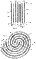
- FIG. 1 A diagrammatic view of a cell unit according to the present invention is seen in FIG. 1.
- Positive plate 10, separator 12 and negative plate 14 constitute an electrochemical unit cell 16.
- Both the positive plate 10 and the negative plate 12 consist of an ultra-thin film 18 of either lead or nickel partially coated on both major faces with a layer of a suitable electrochemically active paste 20.
- the film not only be extremely thin, but that it not be perforated.
- One of the more critical elements of the present invention is that there not be any active material paste 20 at a distance of greater than .005 inches from the film 18 on which it is coated.
- the films 18 utilized in the electrochemical cell are no greater than .005 inches thick. In the preferred embodiments, the films 18 are about .003 to .0015 inches thick. Handling such thin films and incorporating the same into functional electrochemical cells was previously thought to be impossible. In certain ways, the electrochemical cells of the present invention are constructed along the lines of standard electrolytic capacitors.
- a thin layer of the active material paste 20 is applied to a large portion of both major faces of the negative and positive films 18.
- Each layer is, at the most, .005 inches thick, and in the preferred embodiments of the invention, the layers of active material paste 20 are about .002 to .003 inches thick.
- Both positive and negative plates 10, 14 are, at the most, .01 inches thick and in the preferred embodiment have a thickness of about .005 to .008 inches, with an interplate spacing of about .005 to .007 inches.
- the positive plate 10 In each unit cell 16, the positive plate 10, the separator 12 and the negative plate 14 are held against each other in a specific physical relation as seen in FIG. 1. Both major faces of the metal films 18 are coated with active material paste 20, except along alternating horizontal edges 22, 24. On the positive plate 10, the portions of the major faces 26 adjacent to the upper horizontal edge 22 are not coated with the active material paste 20, and on negative plate 14, the portions of the major faces 28 adjacent to the lower horizontal edge 24 are not coated with the active material paste 20.
- plate 10, 14 and separator 12 The physical arrangement of plate 10, 14 and separator 12 is also shown in FIG. 1.
- the positive plate 10 is positioned so that the uncoated portion 26 extends above both the negative plate 12 and the separator 12.
- the separator 12 extends beyond the negative plate 14 but not as far as the positive plate 10 and to the bottom, the separator 12 extends beyond the positive plate 10 but not as far as the negative plate 14. It could, of course, be constructed so that the relative position of the positive and negative plates be reversed.
- the negative and positive film 18 is about 1.5 inches high.
- the uncoated ends extend about 6-8 mm beyond the coated plate, and the separator 12 extends about 2-4 mm beyond the coated plate.
- the surfaces of the film 18 that are to be coated are preferably etched or roughened prior to application of the active paste 20. This allows for a more adequate adhesion between the paste and the film.
- the electrochemical cell is constructed of a single spirally wound unit cell as is shown in FIG. 2.
- the invention could also be employed utilizing parallel stacks of any number of unit cells,
- a single continuous sheet of separator 12 may be employed to separate the negative 14 and positive 10 plates from each other as seen in FIG. 2.
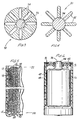
- the preferred terminal connector 32 of the present invention is seen in FIG. 3.
- the terminal connector 32 is a component of the completed electrochemical cell formed near both the top (as seen in FIGs. 1 and 5, the positive terminal) and the bottom (as seen in FIGs. 1 and 5, the negative terminal) of the spirally wound plate and separator unit.
- the preferred terminal connector 32 is a conically shaped conductive element that is about the same diameter as the spirally wound cell, and that has a plurality of oblong shaped apertures 34 radiating outwardly from the center portion of the circle,
- the connector 32 may have a connector post 33 for ease in connection.
- An alternative connector 38 is seen in FIG. 4 This daisy-shaped connector has a plurality of radiating wings 82 protruding out from the body 84 of the connector 80.
- FIG. 5 A unit cell having the physical relationships as shown in FIGs. 1 and 2 and having terminal connectors 32 in place, is seen in FIG. 5.
- the connectors 32 are applied to the top and bottom of the cell (where the uncoated portions 26 and 28 of the negative and positive plates are extending out co-planarly) in a spiral configuration. The effect of such a motion requires that the uncoated portions 26 and 28 are bent radially inwardly. Due to the respective positions of the positive and negative plates 10, 14 and the separator 12, the uncoated portions 26, 28 contact each other and are separated from the opposite polarity plate by the separator 12, as seen in FIG. 4. It can be seen, therefore, that the relative physical positions of the plates and separator is critical in obtaining a proper connection between the terminal connector 32 and the uncoated portions 26, 28 of the plates.
- the terminal arrangement of the present invention provides an improved means for maximizing contact between the respective plates 10, 14 and the terminal connector 32.
- the connectors 32 are permanently attached to the ends of the electrochemical cell by laser welding or plasma arc welding.
- the oblong apertures 34 are spaced to allow access to the interior surface of the connector 32 for welding.
- FIG. 6 An embodiment of the completed electrochemical cell terminal assembly 40 is seen in FIG. 6.
- the spirally wound unit cell 16 is held first in a polypropylene sealed container 42 and second in a stainless steel container 43 that is preferably equipped with vent means (not shown).
- the terminal connectors 32 are held in place by a torroidal brace 42, that holds such connectors 32 in contact with the exterior terminal 44.
- Insulation washer 51 insulates the exterminal terminal 44 from the stainless steel container 43.
- the lead nonperforated film 18 is preferably composed of lead that is at least 99.99% pure.
- the lead may be 99.50% pure and contain about .50% tin,
- the lead film 18 is .005 inches or less thick, and is preferably about .003 to .0015 inches thick.
- active material pastes 20 For lead acid electrochemical cells, there are a number of widely known combinations of active material pastes 20 that are typically used. Any of these commonly utilized systems would be appropriate for use with this invention. For example, sulfated PbO pastes used on both the positive and negative plates provides a satisfactory system, as does the use of PbO and Pb304 on the positive plate and PbO on the negative plate. The use of sponge lead, litharge, red lead or leady oxide is also possible. The only important factor is that the active material paste 20 be of a nature so that it can be applied to the ultra-thin lead film 18 in a consistently thin layer, as described above.
- the use of an absorbent separator 12 is critical, As described above, there are several separator materials that have been disclosed for use specifically with lead acid system electrochemical cells, For the purposes of the present invention, any of the commonly used absorbent permeable separators will work suitably.
- the separator is a glass micro-fiber wherein 90% of the fibers are 1-4 microns in diameter, and 10% of the fibers are longer (up to 1 inch in length), being 95% porous in the uncompressed state.
- the specific gravity of the sulfuric acid electrolyte solution used is between 1.20 and 1.32.
- Electrolyte concentration in the cell is established by adding an excess of electrolyte, and heating the cell in order to vent excess electrolyte.
- the type of vent used on the electrochemical cell may be similar to those described in the literature and known by those with ordinary skill in the art, and operates to vent excess gases when the internal pressure exceeds a certain level.
- the electrolyte remaining in the cell after heating and venting will be in an almost saturated state and some internal pressure (above atmospheric) will be maintained when in its normal operational state.
- the cell of the present invention In its operable state, the cell of the present invention is maintained so that the total void volume of the compressed separator and the active material is substantially filled, yet there is no free electrolyte present.
- the exact amount of electrolyte present in the cell, within these limits, is not critical to the functioning of the present invention.
- FIG. 7 shows the discharge curve for a lead acid electrochemical cell according to an embodiment of the present invention (C) in comparison with discharge curves for the cells described in United States Patent Nos. 3,862,861 of McClelland et al . (A) and 4,769,299 of Nelson (B).
- C lead acid electrochemical cell according to an embodiment of the present invention
- the electrochemical cell used to create the discharge curve seen in FIG 7 has the following characteristics:
- the non-perforated lead film was composed of 99.50% lead and .50% tin; the lead films were .002 inches thick and were coated with a layer of .002 inches thick of sulfated pastes -- the total plate thicknesses being .006 inches; the electrolyte was sulfuric acid with a specific gravity of 1.28; the glass micro-fiber separator was 95% porous in its uncompressed state and contained 90% 1-4 micron diameter fibers and 10% larger fibers up to 1 inch in length and has a surface area of about 2 m2/g.
- the lead films would be 45 inches long and 1.5 inches high, and there would be about 26.0 cm2 of surface area for each gram of active material paste.
- FIG. 8 shows the basic elements required in one embodiment of the manufacture of electrochemical cells of the present invention,
- the central element of the process is the rotatable mandrel 50.
- the mandrel 50 is characterized by a continuous cavity 52 that is capable of receiving the separator 12 during the winding process.
- Drag Rollers 54 are positioned in order to smoothly facilitate the movement of the separator 12 towards the mandrel 50.
- the drag rollers 54 also act to assure that the plates are wound tightly as the cell is being toned.
- the unique mandrel design allows the utilization of a single sheet of separator 12 to be used in each unit Cell. Porous ceramic rollers 56 through which the separator must pass are also shown.
- the ceramic rollers 56 are associated with a reservoir 57 containing electrolyte.
- Metering means 58 are associated with the reservoir 57, that allow controlled amounts of electrolyte into the interior area of the ceramic rollers 56.
- the ceramic rollers 56 are constructed such that electrolyte contained within its interior surfaces will flow to the surface of the rollers, where the electrolyte will be absorbed into The porous separator 12 That passes between the rollers. By this procedure it is possible to assure that a precise amount of electrolyte will be incorporated into the wound electrochemical cell. The amount of electrolyte added to the separator is small enough so that little if any electrolyte will be "squeezed" from the separator 12 during the winding process as the separator and plates 10, 14 are tightly wound together.
- electrolyte could be added to the cell via conventional techniques. For example, after winding the cell and placement into a canister, liquid electrolyte may be added to the cell at this time.
- the negative plate 14 is shown in FIG. 9 as it is advanced toward the mandrel 50.
- the positive plate 10 is seen advancing toward the mandrel 50 from the opposite direction, and both being perpendicular to the general plane of the separator 12.
- the plates 10, 14 are both advanced toward the mandrel 50 and held on a plate carriage 60.
- the plate carriages 60 act as conveyor belts to facilitate the advancement of the plates towards the mandrel.
- the active material paste 20 is applied to both major faces of the plates 10, 14 -- as described above, so that certain areas of the major faces of the plates will not be coated -- at a point not shown.
- the application of the paste 20 may be accomplished by the use of a high pressure brush, or a high pressure spray nozzle. After the active material paste 20 has been applied to the plates 10, 14, the plates are subjected to flash drying by infrared heat sources.
- the paste 20 as applied contains a relatively small amount of moisture, and will dry adequately in a very short period of time.
- some mechanism (not shown) is provided before the paste application zone in which the surfaces of the plates which are to be coated are scored or etched. Such scoring aids in the adhering of the active material paste to the plates, and can be accomplished via chemical or physical processes.
- the plate carriages 60 are designed so that the front edge (the edge closest the mandrel 50) can be moved horizontally towards or away from the mandrel 50. It should be remembered that the plates of the present invention are extremely thin, even when coated, and will have little or no rigidity.
- the production of the electrochemical cell proceeds through a series of steps.
- the process begins by placement of the separator around the drag rollers 54, through the opening in the mandrel 50 and between the two sets of porous ceramic rollers 56.
- the separator sheet must be long enough, both above and below the mandrel 50, to supply sufficient separator for the entire electrochemical cell.
- a single source of separator may be utilized either above or below the mandrel 50, and the initial step of the process would be the threading of the separator through the ceramic rollers 56, past the first drag roller 54, through the opening in the mandrel and past the second drag roller 54. At this stage, the entire amount of separator to be used in the cell has been infiltrated with electrolyte.
- precut sections of separator may be utilized.
- the separator may be placed in the proper position by laterally moving the separator between the various elements and having The correct amount of separator, both above and below the mandrel, for one cell unit.
- the separator would have to be run through the electrolyte containing ceramic rollers prior to being put in place relative to the mandrel.
- the mandrel is rotated about its axis one half turn (as seen by arrow A) so that the opening in the mandrel is now in a horizontal position.
- the plate carriages 60 advance toward the mandrel 50 so that the plates 10, 14 will enter into the gap of separator created between The mandrel 50 and the drag rollers as seen in FIG. 9.
- the drag rollers are then allowed to advance forward in order to engage the plates.
- FIG. 10 shows a detailed view of the mandrel 50 of the present invention, In association with the separator-receiving gap, is a clamp like device 80.
- the clamp 80 operates to facilitate the securing of the separator into the mandrel 50 after it has been put in place. Once cell formation is completed, the clamp 80 releases, and the cell may be more easily removed from the mandrel.
- the plate carriages are moved horizontally away from the mandrel 50.
- the mandrel can now be rotated (counter clockwise in the example shown in FIG. 9), in order to create a cell unit.
- the drag rollers 54 create a certain amount of pressure against the expanding diameter of the cell unit as it is being formed.
- the "tightness" of the winding will be controlled by a number of factors including: the speed of revolution of the mandrel 50; the tension exerted by the drag rollers against the growing cell, and the source tension of the separator and plates relative to the mandrel 50.
- the plates 10, 14 are cut off at the ends of the plate carriages 60 nearest the mandrel 50.
- Tail wrap is attached to the ends of the plates and, once wrapped around the cell, may be heat sealed with a sizing roll or hot drag wires.
- the mandrel and drag rollers may be retracted and the cell may be incorporated into a useful means.
- the processing of the wound and sealed cell may be accomplished by procedures commonly known and available to those skilled in the art.
- the construction and manufacture of the connectors of the present invention is also unique.
- the cell is provided with positive and negative ends that consist of the top and bottom portions of the spirally wound plates.
- the connector is put in place on the top and bottom of the cell by the application of a circular movement, forcing the flexible plate elements to press tightly against each other to form an essentially continuous plate or cover above and below the spirally wound cell.
- the connector is secured via arc welding or laser welding techniques. This construction provides a low resistance pathway for electricity during recharge or discharge.
- both the plates and the separator are being treated as they are being wound into the mandrel.
- the plate is being coated with the active material, which is then flash dried -- all before reaching the mandrel and the growing cell.
- the separator is being impregnated with electrolyte as it passes between the porous ceramic rollers.
- the present invention has applications in all electrochemical cells, and in particular, the lead acid and nickel chromium systems.
- the descriptions given and the example presented are for the purposes of illustration and are not meant to limit the claims of the application as set forth below.
Landscapes
- Chemical & Material Sciences (AREA)
- Chemical Kinetics & Catalysis (AREA)
- Electrochemistry (AREA)
- General Chemical & Material Sciences (AREA)
- Engineering & Computer Science (AREA)
- Manufacturing & Machinery (AREA)
- Secondary Cells (AREA)
- Battery Electrode And Active Subsutance (AREA)
- Manufacture Of Macromolecular Shaped Articles (AREA)
Applications Claiming Priority (5)
| Application Number | Priority Date | Filing Date | Title |
|---|---|---|---|
| US07/366,867 US5047300A (en) | 1989-06-14 | 1989-06-14 | Ultra-thin plate electrochemical cell |
| US366867 | 1989-06-14 | ||
| US413272 | 1989-09-27 | ||
| US07/413,272 US5045086A (en) | 1989-06-14 | 1989-09-27 | Method for manufacture of electrochemical cell |
| EP90911144A EP0494147B1 (de) | 1989-06-14 | 1990-06-14 | Elektrochemische zelle bestehend aus ultradünnen filmen |
Related Parent Applications (2)
| Application Number | Title | Priority Date | Filing Date |
|---|---|---|---|
| EP90911144A Division EP0494147B1 (de) | 1989-06-14 | 1990-06-14 | Elektrochemische zelle bestehend aus ultradünnen filmen |
| EP90911144.5 Division | 1991-01-02 |
Publications (3)
| Publication Number | Publication Date |
|---|---|
| EP0961335A2 true EP0961335A2 (de) | 1999-12-01 |
| EP0961335A3 EP0961335A3 (de) | 2003-10-29 |
| EP0961335B1 EP0961335B1 (de) | 2008-04-30 |
Family
ID=27003549
Family Applications (2)
| Application Number | Title | Priority Date | Filing Date |
|---|---|---|---|
| EP99116070A Expired - Lifetime EP0961335B1 (de) | 1989-06-14 | 1990-06-14 | Verfahren zur Herstellung einer elektrochemischen Zelle mit ultradünnen Platten |
| EP99116071A Expired - Lifetime EP0961336B1 (de) | 1989-06-14 | 1990-06-14 | Aus ultradünnen Filmen hergestellte elektrochemische Zelle |
Family Applications After (1)
| Application Number | Title | Priority Date | Filing Date |
|---|---|---|---|
| EP99116071A Expired - Lifetime EP0961336B1 (de) | 1989-06-14 | 1990-06-14 | Aus ultradünnen Filmen hergestellte elektrochemische Zelle |
Country Status (5)
| Country | Link |
|---|---|
| US (1) | US5045086A (de) |
| EP (2) | EP0961335B1 (de) |
| AT (3) | ATE393968T1 (de) |
| DE (3) | DE69034262D1 (de) |
| ES (1) | ES2146198T3 (de) |
Cited By (1)
| Publication number | Priority date | Publication date | Assignee | Title |
|---|---|---|---|---|
| EP1383197A4 (de) * | 2001-03-30 | 2007-06-06 | Toray Eng Co Ltd | Sekundärbatterie und verfahren zu ihrer herstellung und herstellungseinrichtung für eine sekundärbatterie |
Families Citing this family (36)
| Publication number | Priority date | Publication date | Assignee | Title |
|---|---|---|---|---|
| US5198313A (en) * | 1989-06-14 | 1993-03-30 | Bolder Battery, Inc. | Battery end connector |
| EP0556326A4 (en) * | 1990-11-09 | 1995-03-29 | Weiler Eng Inc | Method and apparatus for winding a core for an electrochemical cell and processing thereof |
| DE4241037C1 (de) * | 1992-12-05 | 1994-04-28 | Deutsche Automobilgesellsch | Elektrochemischer Speicher |
| US5370711A (en) * | 1993-07-21 | 1994-12-06 | Ev Energy Systems, Inc. | Method for making an electrical energy storage device |
| US5958621A (en) * | 1995-05-19 | 1999-09-28 | Johnson Controls Technology Company | Two-step pasting of thin electrodes |
| US6004689A (en) * | 1995-09-27 | 1999-12-21 | Bolder Technologies Corporation | Battery case |
| US5700299A (en) * | 1996-12-12 | 1997-12-23 | Eveready Battery Company, Inc. | Battery core winder and method of winding a battery core |
| US6063525A (en) * | 1997-11-20 | 2000-05-16 | Bipolar Technologies Corp. | Source of electrical power for an electric vehicle and other purposes, and related methods |
| MXPA00007032A (es) | 1998-01-19 | 2002-06-04 | Johnson Controls Tech Co | Cubierta de ventilacion para acumulador. |
| US6051336A (en) * | 1998-01-19 | 2000-04-18 | Johnson Controls Technology | Battery case for thin metal film cells |
| US6221524B1 (en) | 1998-01-19 | 2001-04-24 | Johnson Controls Technology Company | Strap for thin metal film battery |
| DE60000460T2 (de) | 1999-03-04 | 2003-06-05 | Wilson Greatbatch, Ltd. | Gewickelte Hochleistungsbatterie |
| KR100305350B1 (ko) * | 1999-07-01 | 2001-11-01 | 이계안 | Ni-MH 전지의 음극판 조립장치 및 그 공정 |
| US6292381B1 (en) * | 1999-12-16 | 2001-09-18 | S-B Power Tool Company | AC to DC power supply with supplemental energy storage |
| DE10015823A1 (de) * | 2000-03-30 | 2001-10-18 | Epcos Ag | Gehäuster Schichtstapel, Verfahren zur Herstellung des gehäusten Schichtstapels und Verwendung des Verfahrens |
| US6534212B1 (en) * | 2000-05-05 | 2003-03-18 | Hawker Energy Products, Inc. | High performance battery and current collector therefor |
| US6316148B1 (en) | 2000-08-31 | 2001-11-13 | Condord Battery Corporation | Foil-encapsulated, lightweight, high energy electrodes for lead-acid batteries |
| US6586136B1 (en) | 2000-11-16 | 2003-07-01 | Concorde Battery Corporation | Lightweight, low resistance electrode plate for lead-acid batteries |
| US6566010B1 (en) | 2000-11-16 | 2003-05-20 | Concorde Battery Corporation | High energy, lightweight, lead-acid storage battery |
| KR100828275B1 (ko) | 2003-10-21 | 2008-05-07 | 존슨 컨트롤스 테크놀러지 컴퍼니 | 배터리 페이스트 물질 및 방법 |
| US8094771B2 (en) | 2003-11-21 | 2012-01-10 | Global Technologies, Inc. | Nuclear voltaic cell |
| US7011805B2 (en) | 2004-03-19 | 2006-03-14 | Ges Technologies Ip Gmbh | Production of tetrabasic lead sulfate from solid state reactions for the preparation of active plates to be used in lead-acid batteries |
| US20060039852A1 (en) * | 2004-08-19 | 2006-02-23 | Johnson Controls Technology Company | Method for making lead oxide for lead-acid batteries |
| US20080113268A1 (en) * | 2006-10-23 | 2008-05-15 | Buiel Edward R | Recombinant Hybrid Energy Storage Device |
| KR101023865B1 (ko) * | 2009-02-25 | 2011-03-22 | 에스비리모티브 주식회사 | 이차 전지 |
| US8685557B2 (en) | 2010-04-07 | 2014-04-01 | Medtronic, Inc. | Electrode assembly including mandrel having a removable portion |
| US9054387B2 (en) | 2010-04-07 | 2015-06-09 | Medtronic, Inc. | Electrode assembly including mandrel having removable portion |
| US9299971B2 (en) | 2010-10-06 | 2016-03-29 | Medtronic, Inc. | Common carrier for the integrated mandrel battery assembly |
| US8832914B2 (en) | 2010-10-06 | 2014-09-16 | Medtronic, Inc | Coiling device for making an electrode assembly and methods of use |
| US9559339B2 (en) * | 2011-04-19 | 2017-01-31 | Samsung Sdi Co., Ltd. | Secondary battery |
| JP6038803B2 (ja) * | 2011-10-31 | 2016-12-07 | 三洋電機株式会社 | 渦巻電極体を備えた電池及びその製造方法 |
| US9005802B2 (en) | 2011-12-21 | 2015-04-14 | Medtronic, Inc. | Electrode assembly with hybrid weld |
| US9083053B2 (en) | 2011-12-21 | 2015-07-14 | Medtronic, Inc. | Through weld interconnect joint |
| KR102499324B1 (ko) * | 2015-10-30 | 2023-02-13 | 삼성에스디아이 주식회사 | 이차전지용 권취장치 |
| KR102805104B1 (ko) * | 2018-12-31 | 2025-05-08 | 현대자동차주식회사 | 코어-셸 구조를 갖는 활물질을 포함하는 음극, 그 제조방법 및 이를 포함하는 이차전지 |
| DE102022004410B4 (de) | 2022-11-25 | 2024-06-06 | Mercedes-Benz Group AG | Verfahren zum Tränken einer Elektrode mit Elektrolyt |
Family Cites Families (22)
| Publication number | Priority date | Publication date | Assignee | Title |
|---|---|---|---|---|
| US2883443A (en) * | 1956-07-13 | 1959-04-21 | Ruetschi Karl | Lead-acid storage battery |
| DE1248770B (de) * | 1964-05-16 | 1967-08-31 | VARTA AKTIENGESELL SCHAFT, Frankfurt/M | Mi+ hohen Strömen belastbarer elektrischer Akkumulator mit Wickelelektroden |
| FR1510827A (fr) * | 1966-04-01 | 1968-01-26 | Accumulateurs Fixes | Perfectionnements à des cellules électrolytiques, des accumulateurs et des piles électriques |
| US3395043A (en) * | 1967-05-09 | 1968-07-30 | Shoeld Mark | Storage battery having spiral electrodes of the pasted type |
| US3494800A (en) * | 1968-04-08 | 1970-02-10 | Mark Shoeld | Method of making lead acid storage battery |
| DE2403222A1 (de) * | 1974-01-24 | 1975-08-07 | Walter Nimmerrichter | Akkumulator |
| CH590566A5 (de) * | 1974-03-27 | 1977-08-15 | Spiracell Sa | |
| US4064725A (en) * | 1976-10-18 | 1977-12-27 | The Gates Rubber Company | Apparatus for making spirally wound electrochemical cells |
| SU674124A1 (ru) * | 1977-01-06 | 1979-07-15 | Предприятие П/Я В-2410 | Способ намотки в рулон пакета электродов с сепараторами дл химического источника тока |
| US4099401A (en) * | 1977-06-27 | 1978-07-11 | The Gates Rubber Company | Method of producing spirally wound electrochemical cells |
| US4158300A (en) * | 1977-12-16 | 1979-06-19 | The Gates Rubber Company | Apparatus for producing a spirally wound electrochemical cell |
| US4212179A (en) * | 1978-10-12 | 1980-07-15 | The Gates Rubber Company | Driven mandrel and method |
| US4295029A (en) * | 1979-05-29 | 1981-10-13 | The Gates Rubber Company | Battery strap connection welding method |
| SE8005528L (sv) * | 1980-08-01 | 1982-02-05 | Erik G Sundberg | Elektrisk blyackumulator med tunna elektroder |
| JPS58119154A (ja) * | 1982-01-09 | 1983-07-15 | Yuasa Battery Co Ltd | アルカリ蓄電池 |
| JPS59103282A (ja) * | 1982-12-03 | 1984-06-14 | Japan Storage Battery Co Ltd | 渦巻電極体の製造方法 |
| US4495259A (en) * | 1983-02-11 | 1985-01-22 | The Gates Rubber Company | Vibration resistant battery |
| JPS59219868A (ja) * | 1983-05-30 | 1984-12-11 | Shin Kobe Electric Mach Co Ltd | ニツケルカドミウム蓄電池の製造法 |
| US4606982A (en) * | 1985-05-09 | 1986-08-19 | Gates Energy Products, Inc. | Sealed lead-acid cell and method |
| JPS62147661A (ja) * | 1985-12-23 | 1987-07-01 | Sanyo Electric Co Ltd | 渦巻電極体の製造法 |
| US4780379A (en) * | 1987-10-06 | 1988-10-25 | Gates Energy Products, Inc. | Multicell recombinant lead-acid battery with vibration resistant intercell connector |
| US4963446A (en) * | 1989-04-05 | 1990-10-16 | Eveready Battery Co., Inc. | Inwardly indented edge electrode assembly |
-
1989
- 1989-09-27 US US07/413,272 patent/US5045086A/en not_active Expired - Lifetime
-
1990
- 1990-06-14 EP EP99116070A patent/EP0961335B1/de not_active Expired - Lifetime
- 1990-06-14 ES ES90911144T patent/ES2146198T3/es not_active Expired - Lifetime
- 1990-06-14 DE DE69034262T patent/DE69034262D1/de not_active Expired - Lifetime
- 1990-06-14 DE DE69034252T patent/DE69034252D1/de not_active Expired - Lifetime
- 1990-06-14 AT AT99116070T patent/ATE393968T1/de not_active IP Right Cessation
- 1990-06-14 EP EP99116071A patent/EP0961336B1/de not_active Expired - Lifetime
- 1990-06-14 AT AT90911144T patent/ATE190758T1/de not_active IP Right Cessation
- 1990-06-14 AT AT99116071T patent/ATE422717T1/de not_active IP Right Cessation
- 1990-06-14 DE DE69033485T patent/DE69033485T2/de not_active Expired - Fee Related
Cited By (1)
| Publication number | Priority date | Publication date | Assignee | Title |
|---|---|---|---|---|
| EP1383197A4 (de) * | 2001-03-30 | 2007-06-06 | Toray Eng Co Ltd | Sekundärbatterie und verfahren zu ihrer herstellung und herstellungseinrichtung für eine sekundärbatterie |
Also Published As
| Publication number | Publication date |
|---|---|
| EP0961336B1 (de) | 2009-02-11 |
| ES2146198T3 (es) | 2000-08-01 |
| US5045086A (en) | 1991-09-03 |
| ATE422717T1 (de) | 2009-02-15 |
| ATE393968T1 (de) | 2008-05-15 |
| EP0961335A3 (de) | 2003-10-29 |
| DE69033485T2 (de) | 2000-06-29 |
| EP0961336A3 (de) | 2003-10-29 |
| DE69034252D1 (de) | 2008-06-12 |
| DE69033485D1 (de) | 2000-04-20 |
| EP0961335B1 (de) | 2008-04-30 |
| EP0961336A2 (de) | 1999-12-01 |
| ATE190758T1 (de) | 2000-04-15 |
| DE69034262D1 (de) | 2009-03-26 |
Similar Documents
| Publication | Publication Date | Title |
|---|---|---|
| US5045086A (en) | Method for manufacture of electrochemical cell | |
| EP0494147B1 (de) | Elektrochemische zelle bestehend aus ultradünnen filmen | |
| US5047300A (en) | Ultra-thin plate electrochemical cell | |
| US5368961A (en) | Thin plate electrochemical cell | |
| US6949313B2 (en) | Battery with a microcorrugated, microthin sheet of highly porous corroded metal | |
| US6004691A (en) | Fibrous battery cells | |
| US7935445B2 (en) | Lithium ion secondary battery | |
| US20170155171A1 (en) | Lead-acid accumulator and method for manufacturing such an accumulator | |
| WO1997016863A9 (en) | Novel fibrous battery cell design | |
| JP4205209B2 (ja) | 非水電解質二次電池 | |
| EP0352450A1 (de) | Mehrschichtiges Laminat und Aufbau von Separatoren für elektrochemische Zellen | |
| JPH04206468A (ja) | 密閉型アルカリ亜鉛蓄電池 | |
| US3697328A (en) | Duplex electrode construction using continuous metal carrier strip coated on one side with conductive adhesive | |
| WO1994029909A1 (en) | Method and apparatus for assembling electrochemical cell | |
| JPS5933754A (ja) | 鉛蓄電池 | |
| US20240105914A1 (en) | Bipolar battery plate and fabrication thereof | |
| US20140272527A1 (en) | Separator components and system for energy storage and conversion devices | |
| CA1102409A (en) | Battery plates covered with porous thermoplastic resin | |
| JPS607069A (ja) | シ−ル鉛蓄電池の製造方法 | |
| JPS61245469A (ja) | ボタン形アルカリ電池 | |
| JPH02309567A (ja) | 密閉形鉛蓄電池 | |
| JPH09161805A (ja) | 薄型電極を用いた密閉型電池及び製造方法 | |
| JPH0810589B2 (ja) | 鉛蓄電池 | |
| JPH02262237A (ja) | 密閉形鉛蓄電池 | |
| JPH03155057A (ja) | ベント形蓄電池用極板、その製造法並にベント形蓄電池 |
Legal Events
| Date | Code | Title | Description |
|---|---|---|---|
| PUAI | Public reference made under article 153(3) epc to a published international application that has entered the european phase |
Free format text: ORIGINAL CODE: 0009012 |
|
| 17P | Request for examination filed |
Effective date: 19990816 |
|
| AC | Divisional application: reference to earlier application |
Ref document number: 494147 Country of ref document: EP |
|
| AK | Designated contracting states |
Kind code of ref document: A2 Designated state(s): AT BE CH DE DK ES FR GB GR IT LI LU NL SE |
|
| RAP1 | Party data changed (applicant data changed or rights of an application transferred) |
Owner name: GP BATTERIES INTERNATIONAL LIMITED |
|
| PUAL | Search report despatched |
Free format text: ORIGINAL CODE: 0009013 |
|
| AK | Designated contracting states |
Kind code of ref document: A3 Designated state(s): AT BE CH DE DK ES FR GB IT LI LU NL SE |
|
| RIC1 | Information provided on ipc code assigned before grant |
Ipc: 7H 01M 2/28 B Ipc: 7H 01M 2/26 B Ipc: 7H 01M 10/04 B Ipc: 7H 01M 10/12 A |
|
| AKX | Designation fees paid |
Designated state(s): AT BE CH DE DK ES FR GB IT LI LU NL SE |
|
| 17Q | First examination report despatched |
Effective date: 20040622 |
|
| GRAP | Despatch of communication of intention to grant a patent |
Free format text: ORIGINAL CODE: EPIDOSNIGR1 |
|
| RTI1 | Title (correction) |
Free format text: METHOD OF MANUFACTURE OF AN ULTRA-THIN PLATE ELECTROCHEMICAL CELL |
|
| GRAS | Grant fee paid |
Free format text: ORIGINAL CODE: EPIDOSNIGR3 |
|
| GRAA | (expected) grant |
Free format text: ORIGINAL CODE: 0009210 |
|
| AC | Divisional application: reference to earlier application |
Ref document number: 0494147 Country of ref document: EP Kind code of ref document: P |
|
| AK | Designated contracting states |
Kind code of ref document: B1 Designated state(s): AT BE CH DE DK ES FR GB IT LI LU NL SE |
|
| REG | Reference to a national code |
Ref country code: GB Ref legal event code: FG4D |
|
| REG | Reference to a national code |
Ref country code: CH Ref legal event code: EP |
|
| REF | Corresponds to: |
Ref document number: 69034252 Country of ref document: DE Date of ref document: 20080612 Kind code of ref document: P |
|
| REG | Reference to a national code |
Ref country code: SE Ref legal event code: TRGR |
|
| NLV1 | Nl: lapsed or annulled due to failure to fulfill the requirements of art. 29p and 29m of the patents act | ||
| ET | Fr: translation filed | ||
| PG25 | Lapsed in a contracting state [announced via postgrant information from national office to epo] |
Ref country code: NL Free format text: LAPSE BECAUSE OF FAILURE TO SUBMIT A TRANSLATION OF THE DESCRIPTION OR TO PAY THE FEE WITHIN THE PRESCRIBED TIME-LIMIT Effective date: 20080430 Ref country code: ES Free format text: LAPSE BECAUSE OF FAILURE TO SUBMIT A TRANSLATION OF THE DESCRIPTION OR TO PAY THE FEE WITHIN THE PRESCRIBED TIME-LIMIT Effective date: 20080810 |
|
| PG25 | Lapsed in a contracting state [announced via postgrant information from national office to epo] |
Ref country code: AT Free format text: LAPSE BECAUSE OF FAILURE TO SUBMIT A TRANSLATION OF THE DESCRIPTION OR TO PAY THE FEE WITHIN THE PRESCRIBED TIME-LIMIT Effective date: 20080430 |
|
| PG25 | Lapsed in a contracting state [announced via postgrant information from national office to epo] |
Ref country code: DK Free format text: LAPSE BECAUSE OF FAILURE TO SUBMIT A TRANSLATION OF THE DESCRIPTION OR TO PAY THE FEE WITHIN THE PRESCRIBED TIME-LIMIT Effective date: 20080430 Ref country code: DE Free format text: LAPSE BECAUSE OF FAILURE TO SUBMIT A TRANSLATION OF THE DESCRIPTION OR TO PAY THE FEE WITHIN THE PRESCRIBED TIME-LIMIT Effective date: 20080801 |
|
| REG | Reference to a national code |
Ref country code: CH Ref legal event code: PL |
|
| PG25 | Lapsed in a contracting state [announced via postgrant information from national office to epo] |
Ref country code: BE Free format text: LAPSE BECAUSE OF FAILURE TO SUBMIT A TRANSLATION OF THE DESCRIPTION OR TO PAY THE FEE WITHIN THE PRESCRIBED TIME-LIMIT Effective date: 20080430 |
|
| PLBE | No opposition filed within time limit |
Free format text: ORIGINAL CODE: 0009261 |
|
| STAA | Information on the status of an ep patent application or granted ep patent |
Free format text: STATUS: NO OPPOSITION FILED WITHIN TIME LIMIT |
|
| PGFP | Annual fee paid to national office [announced via postgrant information from national office to epo] |
Ref country code: SE Payment date: 20080618 Year of fee payment: 19 |
|
| 26N | No opposition filed |
Effective date: 20090202 |
|
| REG | Reference to a national code |
Ref country code: FR Ref legal event code: ST Effective date: 20090228 |
|
| PG25 | Lapsed in a contracting state [announced via postgrant information from national office to epo] |
Ref country code: LI Free format text: LAPSE BECAUSE OF NON-PAYMENT OF DUE FEES Effective date: 20080630 Ref country code: CH Free format text: LAPSE BECAUSE OF NON-PAYMENT OF DUE FEES Effective date: 20080630 |
|
| PG25 | Lapsed in a contracting state [announced via postgrant information from national office to epo] |
Ref country code: IT Free format text: LAPSE BECAUSE OF NON-PAYMENT OF DUE FEES Effective date: 20080614 Ref country code: FR Free format text: LAPSE BECAUSE OF NON-PAYMENT OF DUE FEES Effective date: 20080630 |
|
| PGFP | Annual fee paid to national office [announced via postgrant information from national office to epo] |
Ref country code: GB Payment date: 20090529 Year of fee payment: 20 |
|
| PG25 | Lapsed in a contracting state [announced via postgrant information from national office to epo] |
Ref country code: LU Free format text: LAPSE BECAUSE OF NON-PAYMENT OF DUE FEES Effective date: 20080614 |
|
| REG | Reference to a national code |
Ref country code: GB Ref legal event code: PE20 Expiry date: 20100613 |
|
| PG25 | Lapsed in a contracting state [announced via postgrant information from national office to epo] |
Ref country code: GB Free format text: LAPSE BECAUSE OF EXPIRATION OF PROTECTION Effective date: 20100613 |
|
| PG25 | Lapsed in a contracting state [announced via postgrant information from national office to epo] |
Ref country code: SE Free format text: LAPSE BECAUSE OF NON-PAYMENT OF DUE FEES Effective date: 20090615 |