EP0960710B1 - Extrusions- und Kalandrieverfahren und Vorrichtung zur Herstellung einer mit Ankernoppen oder anderer Formen versehenen Kunststoffplatte - Google Patents
Extrusions- und Kalandrieverfahren und Vorrichtung zur Herstellung einer mit Ankernoppen oder anderer Formen versehenen Kunststoffplatte Download PDFInfo
- Publication number
- EP0960710B1 EP0960710B1 EP99108263A EP99108263A EP0960710B1 EP 0960710 B1 EP0960710 B1 EP 0960710B1 EP 99108263 A EP99108263 A EP 99108263A EP 99108263 A EP99108263 A EP 99108263A EP 0960710 B1 EP0960710 B1 EP 0960710B1
- Authority
- EP
- European Patent Office
- Prior art keywords
- strips
- synthetic material
- release
- profiling
- profile
- Prior art date
- Legal status (The legal status is an assumption and is not a legal conclusion. Google has not performed a legal analysis and makes no representation as to the accuracy of the status listed.)
- Expired - Lifetime
Links
Images


Classifications
-
- B—PERFORMING OPERATIONS; TRANSPORTING
- B29—WORKING OF PLASTICS; WORKING OF SUBSTANCES IN A PLASTIC STATE IN GENERAL
- B29C—SHAPING OR JOINING OF PLASTICS; SHAPING OF MATERIAL IN A PLASTIC STATE, NOT OTHERWISE PROVIDED FOR; AFTER-TREATMENT OF THE SHAPED PRODUCTS, e.g. REPAIRING
- B29C43/00—Compression moulding, i.e. applying external pressure to flow the moulding material; Apparatus therefor
- B29C43/22—Compression moulding, i.e. applying external pressure to flow the moulding material; Apparatus therefor of articles of indefinite length
- B29C43/222—Compression moulding, i.e. applying external pressure to flow the moulding material; Apparatus therefor of articles of indefinite length characterised by the shape of the surface
-
- B—PERFORMING OPERATIONS; TRANSPORTING
- B29—WORKING OF PLASTICS; WORKING OF SUBSTANCES IN A PLASTIC STATE IN GENERAL
- B29C—SHAPING OR JOINING OF PLASTICS; SHAPING OF MATERIAL IN A PLASTIC STATE, NOT OTHERWISE PROVIDED FOR; AFTER-TREATMENT OF THE SHAPED PRODUCTS, e.g. REPAIRING
- B29C43/00—Compression moulding, i.e. applying external pressure to flow the moulding material; Apparatus therefor
- B29C43/32—Component parts, details or accessories; Auxiliary operations
- B29C43/50—Removing moulded articles
-
- B—PERFORMING OPERATIONS; TRANSPORTING
- B29—WORKING OF PLASTICS; WORKING OF SUBSTANCES IN A PLASTIC STATE IN GENERAL
- B29C—SHAPING OR JOINING OF PLASTICS; SHAPING OF MATERIAL IN A PLASTIC STATE, NOT OTHERWISE PROVIDED FOR; AFTER-TREATMENT OF THE SHAPED PRODUCTS, e.g. REPAIRING
- B29C59/00—Surface shaping of articles, e.g. embossing; Apparatus therefor
- B29C59/02—Surface shaping of articles, e.g. embossing; Apparatus therefor by mechanical means, e.g. pressing
- B29C59/022—Surface shaping of articles, e.g. embossing; Apparatus therefor by mechanical means, e.g. pressing characterised by the disposition or the configuration, e.g. dimensions, of the embossments or the shaping tools therefor
Definitions
- the invention relates to a device for the continuous production of a Anchor studs or other forms provided plastic plate.
- This invention Device is, for example, as part of an extrusion line for thermoplastic Plastics used to extrude anchor plates that are considered to be chemically resistant Lining or lining for components such as pipes, pipelines, channels, basins, Containers, pillars, etc. used from usually cementitious materials such as concrete become.
- a non-positive connection is achieved.
- the invention relates to a method for producing such Plastic sheets.
- the anchor plate is usually made of thermoplastic materials with high temperature and chemical resistance such as polyethylene, polypropylene, PVC, PVDF, ETFE or E-CTFE produced in a continuous extrusion and calendering process.
- the plastic plate can be single-layered or co-extruded multi-layered be extruded or as a single or multi-layer plastic plate with aluminum or other Substrates, woven or nonwoven fabrics of polyester or glass fibers laminated and coated be.
- DE 296 15 818 U introduces a device which trapezoidal elevations on a Plastic plate in a second operation mechanically squeezes in the way that a undercut shape is generated.
- EP 0436 058 B1 protects a mold obtained by pouring plastic melt into the wing-shaped mold nests of a roller is formed.
- the mold nests are over the Circumference of the roller attached and firmly connected to the roller.
- the melt fills one undercut, wing-shaped, is cooled and cooled in the state of Ripped roll.
- the wing-shaped form is when tearing out of the roll on a Side deformed.
- the procedural mass accumulations at the foot of the wing-shaped Shape cause strong during cooling on the smooth side of the plastic plate visible sink marks due to the disappearance of the thermoplastic material.
- DE 3108972 A1 describes a method in which by injection molding be connected to a smooth plate to an anchor plate. This method requires several operations: making the injection molds, making the plate, Welding the injection molds with the plate. This procedure causes high Manufacturing costs compared to continuous extrusion.
- Document DE 19647232 describes a method according to the respective preambles of claims 1 and 3 and a Device according to the genus of the preamble of claims 4 and 9.
- the object of the invention is to provide a method which allows a continuous production of plastic plates of the type mentioned in one operation, which allows the production of particularly frictional anchor shapes such that this example: in the form of upside down cones or Pyramids or are made in the form of extruded transverse to the direction of production web profiles and does not weaken the anchor or the connection between the armature and plate during manufacture, not deformed or damaged.
- Another object of the invention is to provide an apparatus for producing such plastic sheets.
- the device according to the invention has various advantages. Due to the movable mold / mold strips becomes the continuous production of anchor shapes Non-destructively possible on a plastic plate. This allows particularly non-positive Anchor shapes are produced economically, which so far only in several Operations on a smooth plate could be welded. By simple Replacing the movable mold / demoulding strips can be done without time-consuming changes of complete rolls on the same device and the same chill roll different anchor shapes are extruded. This allows different market segments and their different requirements without major investment for multiple rolls to be served. The previous limitation of the width of web plates in the extrusion direction is overcome. This eliminates the expensive prefabrication by welding.
- An economical application of the device according to the invention is the continuous Extrusion of anchor plates made of thermoplastic materials for corrosion protection and the insulation of concrete buildings and structures.
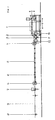
- Fig. I shows a known extrusion plant consisting of the extruder 1, the Flat nozzle 2, the 3-roll calender 3, the trigger 4, the cooling section 5, the Rand4.000eiricardi 6, the cross-section device 7, the winder 8 and a support table 9.
- the processed plastic is melted, homogenized and for Flat nozzle promoted.
- the flat die forms the melt into a liquid band.
- the formed melt is from the flat die 2 in the first nip of the calender. 3 cast.
- the calender 3 consists of the rollers 10, 11 and 12, preferably are arranged horizontally.
- the roller 11 is in the sense of the device according to the invention executed.
- the individual rollers are individually driven and individual tempered.
- the job of the calender is to melt the melt into a sheet or foil Mooring knobs or other forms to shape and cool.
- the deduction 4 immediately after the calender 3 is designed as a rubberized pair of rollers and serves the tension-free Pull off the anchor plate. On the following cooling section 5, the plastic plate cools continue and it is the edge section 6. After a second print 4 the plate is cut to the desired lengths 7.
- the winder 8 winds thin Plates on, the support table 9 receives the rigid plates.
- Fig. 2 shows the inventive device in the application as a shaping Cooling roller 11 and a counter-roll 10 with a smooth surface in a horizontal 3-roll calender 3.
- the device according to the invention consists of the roller 11 and a stable roll shell 17, the peripheral circumferential cooling holes 15 on the having entire bale length of the roller.
- the cooling holes 15 lead the roller 11th heat supplied by the plastic melt again.
- the temperature at the Roll surface and in the forming areas of the roll is kept constant.
- the outer surface of the roll shell 17 is designed as a polygon, for example with a Division of 32 flat spots.
- the flat areas are arranged on the circumference, that alternate the flat areas with the peripheral cooling holes 15. Therefore, the flat locations on the roll shell transversely to the outer shell 17 are pierced.
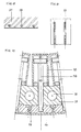
- Fig. 3 shows in plan view the device according to the invention consisting of the Form / Entform strips 13 and holes 20 on the longitudinal side of the Form- / Entform strips for the shaping of the anchors.
- Fig. 4 illustrates in section the structure of the device according to the invention consisting of the roll shell 17 with flat spots on the outer surface and the Cooling holes 15, the Form- / Entform strips 13 which from the piston rod 18 in Cylinder 16 to be moved.
- the opening and closing of the mold / demoulding strips 13 is preferably carried out hydraulically or pneumatically.
- the time of opening or Closing the piston rods can mechanically via control discs or electrically over Solenoid valves are controlled.
- Fig. 5 shows in section the installation of an anchor plate 20 in the concrete 21. Die Anchor plate is used as a formwork and the concrete is in liquid form behind the Cast anchor plate. Fig. 5 makes the excellent frictional connection between the anchor plate and the concrete clearly. It also becomes clear that the Anchor plate 20 continuously in an extrusion process only with the help of the invention Device can be produced.
- the shape of the anchors or other shapes will vary from the shape chosen Form / release strips 13 determined.
- the forms are inventively on the Long side of the mold / demolding strips 13 incorporated. This allows together with the movable arrangement of the mold / mold strips 13, the non-destructive demolding.
- the forming roll can be made with differently shaped mold / mold strips 13 are used. The forming roller is thus flexible and can quickly be converted to new forms by swapping the mold / mold strips become.
- 6 shows in plan view the anchor plate 22 with round shapes such, that the anchor is like an upside down cone.
- Fig. 7 shows the Anchor 23 as a pyramid turned upside down.
- the molds incorporated in the mold / mold strips may be positive or negative be executed the moldings or on the roll shell.
- the forms can Cylindrical, with a positive or negative cone, undercut, in longitudinal or Transversely grooved, pyramidal or executed in combinations thereof.
- the Shapes can be round, square, rectangular, oval or polygonal, T-shaped grooved or in combinations thereof.
- the surface of the shapes can be smoothly honed, Polished, roughened, eroded, spirally milled, drilled, grooved or in combinations thereof be executed.
- the dimensions of the shapes depend on the height and width of the shapes Mold and Entformancen and the stroke of the hydraulic or pneumatic cylinder.
- the Distance between the molds depends on the width and length of the mold and Entformancen. Radial or axial vents in the roll shell or in the mold and Mold release strips improve the continuous shaping of the mold.
Landscapes
- Engineering & Computer Science (AREA)
- Mechanical Engineering (AREA)
- Extrusion Moulding Of Plastics Or The Like (AREA)
- Moulds For Moulding Plastics Or The Like (AREA)
- Shaping Of Tube Ends By Bending Or Straightening (AREA)
Description
in der Form von quer zur Produktionsrichtung extrudierten Stegprofilen ausgeführt sind und die die Anker oder die Verbindung zwischen Anker und Platte bei der Herstellung nicht schwächt, nicht verformt oder beschädigt. Eine weitere Aufgabe der Erfindung liegt darin, eine Vorrichtung zum Herstellen von derartigen Kunststoffplatten zu schaffen.
Claims (9)
- Verfahren zum Herstellen von Kunststoffplatten (20), vorzugsweise aus thermoplastischem Kunststoff, wobei der Kunststoff durch Extrudieren aufgeschmolzen und in einer Flachdüse (2) zu einem flachen Band geformt und anschließend durch mindestens einen Walzenspalt geführt wird, dessen mindestens eine oder beide Walzen (10, 11, 12) mit negativen oder positiven Formen versehen sind, dadurch gekennzeichnet, daß Form-/Entform-Leisten (13) über den Umfang einer temperierten Kalanderwalze (10, 11, 12) angeordnet werden, die zur zerstörungsfreien Freigabe der kontinuierlich ausgebildeten Formen beweglich gelagert werden.
- Verfahren nach Anspruch 1, dadurch gekennzeichnet, daß die Form-/Entform-Leisten (13) radial nach außen bewegt werden.
- Verfahren zum Herstellen von Kunststoffplatten (20), vorzugsweise aus thermoplastischem Kunststoff, wobei der Kunststoff durch Extrudieren aufgeschmolzen und in einer Flachdüse (2) zu einem flachen Band geformt und anschließend durch mindestens einen Spalt geführt wird dadurch gekennzeichnet, dass der Spalt von einer temperierten Platte begrenzt wird, die mit negativen oder positiven Formen versehen ist, und, dass zur zerstörungsfreien Freigabe der kontinuierlich ausgebildeten Formen Form-/Entform-Leisten auf einer Fläche der temperierten Platte beweglich vorgesehen werden.
- Vorrichtung zum Herstellen von Kunststoffplatten (20), vorzugsweise aus thermoplastischem Kunststoff, mit einem Extruder (1) und einer Flachdüse (2) durch die der aufgeschmolzene Kunststoff durch mindestens aus zwei Walzen (10, 11, 12) gebildeten Walzenspalt führbar ist, wobei mindestens eine der Walzen (11) mit negativen oder positiven Formen versehen ist, dadurch gekennzeichnet, daß zur zerstörungsfreien Freigabe der kontinuierlich ausgebildeten Formen Form-/Entform-Leisten (13) über den Umfang einer temperierten Kalanderwalze (10, 11, 12) beweglich ausgebildet sind.
- Vorrichtung nach Anspruch 4, dadurch gekennzeichnet, daß die Form-/Entform-Leisten (13) radial nach außen beweglich gelagert sind.
- Vorrichtung nach mindestens einem der Ansprüche 4 oder 5,dadurch gekennzeichnet, daß die Form-/Entform-Leisten (13) mittels in den Walzen (10, 11, 12) angeordneten Kolben-/Zylinder-Anordnungen (16) hydraulisch oder pneumatisch radial bewegbar sind.
- Vorrichtung nach mindestens einem der Ansprüche 8 bis 12,dadurch gekennzeichnet, daß die in die Form-/Entform-Leisten (13) eingearbeiteten Formen als auf den Kopf gestellte Kegel oder Pyramiden ausgeführt sind.
- Vorrichtung nach den Ansprüchen 4 bis 7,dadurch gekennzeichnet, daß die in die Form-/Entform-Leisten (13) eingearbeiteten Formen als Stegprofile quer zur Produktionsrichtung ausgeführt sind.
- Vorrichtung zum Herstellen von Kunststoffplatten (20), vorzugsweise aus thermoplastischem Kunststoff, mit einem Extruder (1) und einer Flachdüse (2), durch die der aufgeschmolzene Kunststoff durch einen Spalt führbar ist, dadurch gekennzeichnet, dass der Spalt von einer temperierten Platte begrenzt wird, die mit negativen oder positiven Formen versehen ist und, dass zur zerstörungsfreien Freigabe der kontinuierlich ausgebildeten Formen Form-/Entform-Leisten auf der Fläche der temperierten Platte beweglich vorgesehen sind.
Priority Applications (1)
| Application Number | Priority Date | Filing Date | Title |
|---|---|---|---|
| AT99108263T ATE247550T1 (de) | 1998-04-28 | 1999-04-27 | Extrusions- und kalandrieverfahren und vorrichtung zur herstellung einer mit ankernoppen oder anderer formen versehenen kunststoffplatte |
Applications Claiming Priority (2)
| Application Number | Priority Date | Filing Date | Title |
|---|---|---|---|
| AT71198 | 1998-04-28 | ||
| AT0071198A AT410193B (de) | 1998-04-28 | 1998-04-28 | Verfahren und vorrichtung zum herstellen von kunststoffplatten mit hinterschnittenen, einstückigen ansätzen sowie eine derartige kunststoffplatte |
Publications (3)
| Publication Number | Publication Date |
|---|---|
| EP0960710A2 EP0960710A2 (de) | 1999-12-01 |
| EP0960710A3 EP0960710A3 (de) | 2000-05-24 |
| EP0960710B1 true EP0960710B1 (de) | 2003-08-20 |
Family
ID=3497797
Family Applications (1)
| Application Number | Title | Priority Date | Filing Date |
|---|---|---|---|
| EP99108263A Expired - Lifetime EP0960710B1 (de) | 1998-04-28 | 1999-04-27 | Extrusions- und Kalandrieverfahren und Vorrichtung zur Herstellung einer mit Ankernoppen oder anderer Formen versehenen Kunststoffplatte |
Country Status (6)
| Country | Link |
|---|---|
| EP (1) | EP0960710B1 (de) |
| AT (2) | AT410193B (de) |
| DE (1) | DE59906636D1 (de) |
| DK (1) | DK0960710T3 (de) |
| ES (1) | ES2209271T3 (de) |
| PT (1) | PT960710E (de) |
Cited By (1)
| Publication number | Priority date | Publication date | Assignee | Title |
|---|---|---|---|---|
| EP2806083A1 (de) | 2013-05-24 | 2014-11-26 | Agru Kunststofftechnik Gmbh | Vorrichtung zur Befestigung von Kunststoffplatten an Bauwerken oder Bauteilen und Verfahren zum Auskleiden von Bauteilen oder Bauwerken mit Kunststoffplatten |
Families Citing this family (2)
| Publication number | Priority date | Publication date | Assignee | Title |
|---|---|---|---|---|
| JP4409141B2 (ja) | 1999-10-19 | 2010-02-03 | アロイス・グルーバー・ゲーエムベーハー | アンダーカット部を備えるプラスチックパネルと、これと一体の付設物の製造方法と製造装置 |
| DE10229883B4 (de) * | 2002-07-03 | 2005-06-02 | Körner, Ulrich | Extrusionsanlage zur Herstellung einer Kunststoffplatte mit Ankernoppen |
Family Cites Families (8)
| Publication number | Priority date | Publication date | Assignee | Title |
|---|---|---|---|---|
| US2816323A (en) * | 1953-04-22 | 1957-12-17 | Charles G Munger | Method of making plastic lined concrete pipe and joints therein |
| US4323533A (en) * | 1979-08-17 | 1982-04-06 | Monsanto Company | Rotary forming of articles |
| DE2934799A1 (de) * | 1979-08-29 | 1981-03-12 | Friedrichsfeld Gmbh, Steinzeug- Und Kunststoffwerke, 6800 Mannheim | Betonschutz-plattierung |
| DE3108972A1 (de) * | 1981-03-10 | 1982-09-23 | Steuler Industriewerke GmbH, 5410 Höhr-Grenzhausen | Verfahren zur herstellung von grossflaechigen, als verlorene schalung einsetzbaren auskleidungsplatten |
| US4957425A (en) * | 1989-05-15 | 1990-09-18 | Fay Rudolph J | Apparatus for producing shaped products |
| ATE96077T1 (de) * | 1990-01-05 | 1993-11-15 | Gruber Alois Agru Gmbh | Verfahren zur herstellung von noppenplatten aus kunststoff und noppenplatte. |
| DE19647232A1 (de) * | 1996-08-06 | 1998-02-12 | Gse Lining Technology Gmbh | Betonschutzplatte |
| DE29615818U1 (de) * | 1996-09-12 | 1996-10-31 | GFA Industrie-Abdichtungssysteme GmbH, 21218 Seevetal | Vorrichtung zur Herstellung einer mit Befestigungsnoppen versehenen Schutzplatte |
-
1998
- 1998-04-28 AT AT0071198A patent/AT410193B/de not_active IP Right Cessation
-
1999
- 1999-04-27 AT AT99108263T patent/ATE247550T1/de active
- 1999-04-27 ES ES99108263T patent/ES2209271T3/es not_active Expired - Lifetime
- 1999-04-27 DE DE59906636T patent/DE59906636D1/de not_active Expired - Lifetime
- 1999-04-27 EP EP99108263A patent/EP0960710B1/de not_active Expired - Lifetime
- 1999-04-27 DK DK99108263T patent/DK0960710T3/da active
- 1999-04-27 PT PT99108263T patent/PT960710E/pt unknown
Cited By (1)
| Publication number | Priority date | Publication date | Assignee | Title |
|---|---|---|---|---|
| EP2806083A1 (de) | 2013-05-24 | 2014-11-26 | Agru Kunststofftechnik Gmbh | Vorrichtung zur Befestigung von Kunststoffplatten an Bauwerken oder Bauteilen und Verfahren zum Auskleiden von Bauteilen oder Bauwerken mit Kunststoffplatten |
Also Published As
| Publication number | Publication date |
|---|---|
| PT960710E (pt) | 2004-01-30 |
| ES2209271T3 (es) | 2004-06-16 |
| AT410193B (de) | 2003-02-25 |
| EP0960710A3 (de) | 2000-05-24 |
| DE59906636D1 (de) | 2003-09-25 |
| ATA71198A (de) | 2002-07-15 |
| EP0960710A2 (de) | 1999-12-01 |
| DK0960710T3 (da) | 2003-11-17 |
| ATE247550T1 (de) | 2003-09-15 |
Similar Documents
| Publication | Publication Date | Title |
|---|---|---|
| EP0693008B1 (de) | Beulversteifung | |
| DE2147876C3 (de) | Verfahren und Vorrichtung zum Herstellen von Hohlplattenprodukten aus thermoplastischem Kunstharz | |
| DE3035271C2 (de) | Verfahren zum Prägen von Mustern, insbesondere von maßhaltigen mikroprismatischen reflektierenden Strukturen, in bandförmige thermoplastische Kunststoffbahnen und Vorrichtung zur Durchführung dieses Verfahrens | |
| EP0409021B1 (de) | Vorrichtung und Verfahren zur Herstellung von Rohrkörpern | |
| DE3018194C2 (de) | Verfahren zum Herstellen von Rohren oder Behältern aus Kunststoff | |
| DE69515447T2 (de) | Verfahren und Vorrichtung zur Herstellung eines Flächenhaftverschluss | |
| EP2688737B1 (de) | Vorrichtung zum herstellen von tubenkörpern | |
| DE2948235A1 (de) | Verfahren zur herstellung einer mit glasfasern verstaerkten harzplatte | |
| DE3622559C2 (de) | ||
| EP2177702A1 (de) | Hohlprofil, insbesondere Abstandhalterrohr für eine Isolierverglasung, sowie Vorrichtung und Verfahren zur Herstellung des Hohlprofils | |
| EP2382075A1 (de) | Verfahren zur herstellung eines wärmeisolierten leitungsrohres | |
| EP2969478B1 (de) | Schlauchbeutel, verfahren und vorrichtung zur herstellung von schlauchbeuteln | |
| DE2158141B2 (de) | Verfahren und Vorrichtung zum Herstellen einer verstreckten Folienbahn aus thermoplastischem Kunststoff | |
| DE2617140A1 (de) | Vorrichtung zur herstellung von rohren aus schraubenlinienfoermig gewickelten bahnen | |
| WO2001028754A1 (de) | Verfahren und vorrichtung zum herstellen von kunststoffplatten mit hinterschnittenen, einstückigen ansätzen sowie eine derartige kunststoffplatte | |
| DE69917473T2 (de) | Laminiervorrichtung | |
| DE69707763T2 (de) | Verfahren und Vorrichtung zum Herstellen von Rohren aus wiederverwendetem thermoplastischem Kunststoff | |
| DE1988760U (de) | Bauplatte. | |
| EP0960710B1 (de) | Extrusions- und Kalandrieverfahren und Vorrichtung zur Herstellung einer mit Ankernoppen oder anderer Formen versehenen Kunststoffplatte | |
| DE10112736A1 (de) | Heizwalze für eine Heizeinrichtung zum Erwärmen einer Folienbahn aus thermoplastischem Kunststoff | |
| EP2460642A1 (de) | Vorrichtungen und Verfahren zur Herstellung eines duroplastischen halbwabenförmigen Streifens sowie einer duroplastischen Wabenstruktur | |
| EP0515952A2 (de) | Verfahren zum Herstellen von Pfeilerverschalungen | |
| DE2124094A1 (de) | Wellrohr aus thermoplastischem kunststoff und verfahren zu seiner herstellung | |
| DE10229883B4 (de) | Extrusionsanlage zur Herstellung einer Kunststoffplatte mit Ankernoppen | |
| EP0294507A1 (de) | Verfahren und Vorrichtung zur Herstellung von Noppenplatten, nach diesem Verfahren hergestellte Noppenplatte und deren Verwendung |
Legal Events
| Date | Code | Title | Description |
|---|---|---|---|
| PUAI | Public reference made under article 153(3) epc to a published international application that has entered the european phase |
Free format text: ORIGINAL CODE: 0009012 |
|
| AK | Designated contracting states |
Kind code of ref document: A2 Designated state(s): AT BE CH CY DE DK ES FI FR GB GR IE IT LI LU MC NL PT SE |
|
| AX | Request for extension of the european patent |
Free format text: AL;LT;LV;MK;RO;SI |
|
| PUAL | Search report despatched |
Free format text: ORIGINAL CODE: 0009013 |
|
| AK | Designated contracting states |
Kind code of ref document: A3 Designated state(s): AT BE CH CY DE DK ES FI FR GB GR IE IT LI LU MC NL PT SE |
|
| AX | Request for extension of the european patent |
Free format text: AL;LT;LV;MK;RO;SI |
|
| RIC1 | Information provided on ipc code assigned before grant |
Free format text: 7B 29C 43/24 A, 7B 29C 43/50 B, 7B 29C 43/46 B, 7B 29C 43/22 B |
|
| 17P | Request for examination filed |
Effective date: 20001028 |
|
| AKX | Designation fees paid |
Free format text: AT BE CH CY DE DK ES FI FR GB GR IE IT LI LU MC NL PT SE |
|
| 17Q | First examination report despatched |
Effective date: 20010531 |
|
| GRAH | Despatch of communication of intention to grant a patent |
Free format text: ORIGINAL CODE: EPIDOS IGRA |
|
| RTI1 | Title (correction) |
Free format text: METHOD ET APPARATUS FOR EXTRUDING AND CALENDERING A PLASTIC SHEET PROVIDED WITH ANCHORING PROJECTIONS OR SIMILAR FORMS |
|
| RTI1 | Title (correction) |
Free format text: METHOD ET APPARATUS FOR EXTRUDING AND CALENDERING A PLASTIC SHEET PROVIDED WITH ANCHORING PROJECTIONS OR SIMILAR FORMS |
|
| GRAH | Despatch of communication of intention to grant a patent |
Free format text: ORIGINAL CODE: EPIDOS IGRA |
|
| GRAA | (expected) grant |
Free format text: ORIGINAL CODE: 0009210 |
|
| AK | Designated contracting states |
Designated state(s): AT BE CH CY DE DK ES FI FR GB GR IE IT LI LU MC NL PT SE |
|
| REG | Reference to a national code |
Ref country code: GB Ref legal event code: FG4D Free format text: NOT ENGLISH |
|
| REG | Reference to a national code |
Ref country code: CH Ref legal event code: EP |
|
| REG | Reference to a national code |
Ref country code: IE Ref legal event code: FG4D Free format text: GERMAN |
|
| REF | Corresponds to: |
Ref document number: 59906636 Country of ref document: DE Date of ref document: 20030925 Kind code of ref document: P |
|
| REG | Reference to a national code |
Ref country code: SE Ref legal event code: TRGR |
|
| REG | Reference to a national code |
Ref country code: GR Ref legal event code: EP Ref document number: 20030403762 Country of ref document: GR |
|
| GBT | Gb: translation of ep patent filed (gb section 77(6)(a)/1977) |
Effective date: 20031010 |
|
| REG | Reference to a national code |
Ref country code: DK Ref legal event code: T3 |
|
| ET | Fr: translation filed | ||
| REG | Reference to a national code |
Ref country code: ES Ref legal event code: FG2A Ref document number: 2209271 Country of ref document: ES Kind code of ref document: T3 |
|
| PLBE | No opposition filed within time limit |
Free format text: ORIGINAL CODE: 0009261 |
|
| STAA | Information on the status of an ep patent application or granted ep patent |
Free format text: STATUS: NO OPPOSITION FILED WITHIN TIME LIMIT |
|
| 26N | No opposition filed |
Effective date: 20040524 |
|
| PGFP | Annual fee paid to national office [announced via postgrant information from national office to epo] |
Ref country code: MC Payment date: 20100421 Year of fee payment: 12 |
|
| PG25 | Lapsed in a contracting state [announced via postgrant information from national office to epo] |
Ref country code: MC Free format text: LAPSE BECAUSE OF NON-PAYMENT OF DUE FEES Effective date: 20110430 |
|
| REG | Reference to a national code |
Ref country code: DE Ref legal event code: R082 Ref document number: 59906636 Country of ref document: DE Representative=s name: ABP ANWAELTE BURGER & PARTNER RECHTSANWALT GMB, AT Ref country code: DE Ref legal event code: R082 Ref document number: 59906636 Country of ref document: DE Representative=s name: ANWAELTE BURGER UND PARTNER RECHTSANWALTSKANZL, AT Ref country code: DE Ref legal event code: R082 Ref document number: 59906636 Country of ref document: DE Representative=s name: ANWAELTE BURGER UND PARTNER RECHTSANWALT GMBH, AT Ref country code: DE Ref legal event code: R082 Ref document number: 59906636 Country of ref document: DE Representative=s name: FRANK OPPERMANN, DE |
|
| REG | Reference to a national code |
Ref country code: DE Ref legal event code: R082 Ref document number: 59906636 Country of ref document: DE Representative=s name: ABP ANWAELTE BURGER & PARTNER RECHTSANWALT GMB, AT Ref country code: DE Ref legal event code: R082 Ref document number: 59906636 Country of ref document: DE Representative=s name: ANWAELTE BURGER UND PARTNER RECHTSANWALTSKANZL, AT Ref country code: DE Ref legal event code: R082 Ref document number: 59906636 Country of ref document: DE Representative=s name: ANWAELTE BURGER UND PARTNER RECHTSANWALT GMBH, AT |
|
| REG | Reference to a national code |
Ref country code: CH Ref legal event code: NV Representative=s name: ABP PATENT NETWORK AG, CH |
|
| REG | Reference to a national code |
Ref country code: FR Ref legal event code: PLFP Year of fee payment: 18 |
|
| REG | Reference to a national code |
Ref country code: CH Ref legal event code: PCAR Free format text: NEW ADDRESS: OTHMARSTRASSE 8, 8008 ZUERICH (CH) |
|
| REG | Reference to a national code |
Ref country code: FR Ref legal event code: PLFP Year of fee payment: 19 |
|
| REG | Reference to a national code |
Ref country code: DE Ref legal event code: R082 Ref document number: 59906636 Country of ref document: DE Representative=s name: ABP BURGER RECHTSANWALTSGESELLSCHAFT MBH, DE Ref country code: DE Ref legal event code: R082 Ref document number: 59906636 Country of ref document: DE Representative=s name: ABP ANWAELTE BURGER & PARTNER RECHTSANWALT GMB, AT |
|
| PGFP | Annual fee paid to national office [announced via postgrant information from national office to epo] |
Ref country code: FI Payment date: 20170424 Year of fee payment: 19 |
|
| REG | Reference to a national code |
Ref country code: FR Ref legal event code: PLFP Year of fee payment: 20 |
|
| PGFP | Annual fee paid to national office [announced via postgrant information from national office to epo] |
Ref country code: NL Payment date: 20180326 Year of fee payment: 20 Ref country code: LU Payment date: 20180323 Year of fee payment: 20 Ref country code: GB Payment date: 20180321 Year of fee payment: 20 Ref country code: DK Payment date: 20180326 Year of fee payment: 20 |
|
| PGFP | Annual fee paid to national office [announced via postgrant information from national office to epo] |
Ref country code: BE Payment date: 20180323 Year of fee payment: 20 Ref country code: PT Payment date: 20180321 Year of fee payment: 20 Ref country code: IT Payment date: 20180309 Year of fee payment: 20 Ref country code: IE Payment date: 20180320 Year of fee payment: 20 Ref country code: GR Payment date: 20180319 Year of fee payment: 20 Ref country code: SE Payment date: 20180321 Year of fee payment: 20 |
|
| PGFP | Annual fee paid to national office [announced via postgrant information from national office to epo] |
Ref country code: CH Payment date: 20180416 Year of fee payment: 20 Ref country code: ES Payment date: 20180503 Year of fee payment: 20 Ref country code: DE Payment date: 20180322 Year of fee payment: 20 |
|
| PGFP | Annual fee paid to national office [announced via postgrant information from national office to epo] |
Ref country code: AT Payment date: 20180323 Year of fee payment: 20 Ref country code: FR Payment date: 20180403 Year of fee payment: 20 |
|
| PGFP | Annual fee paid to national office [announced via postgrant information from national office to epo] |
Ref country code: CY Payment date: 20180426 Year of fee payment: 20 |
|
| PG25 | Lapsed in a contracting state [announced via postgrant information from national office to epo] |
Ref country code: FI Free format text: LAPSE BECAUSE OF NON-PAYMENT OF DUE FEES Effective date: 20180427 |
|
| REG | Reference to a national code |
Ref country code: DE Ref legal event code: R082 Ref document number: 59906636 Country of ref document: DE Representative=s name: ABP BURGER RECHTSANWALTSGESELLSCHAFT MBH, DE |
|
| REG | Reference to a national code |
Ref country code: DE Ref legal event code: R071 Ref document number: 59906636 Country of ref document: DE |
|
| REG | Reference to a national code |
Ref country code: DK Ref legal event code: EUP Effective date: 20190427 |
|
| REG | Reference to a national code |
Ref country code: CH Ref legal event code: PL |
|
| REG | Reference to a national code |
Ref country code: NL Ref legal event code: MK Effective date: 20190426 |
|
| REG | Reference to a national code |
Ref country code: GB Ref legal event code: PE20 Expiry date: 20190426 |
|
| REG | Reference to a national code |
Ref country code: SE Ref legal event code: EUG |
|
| REG | Reference to a national code |
Ref country code: IE Ref legal event code: MK9A |
|
| REG | Reference to a national code |
Ref country code: BE Ref legal event code: MK Effective date: 20190427 |
|
| REG | Reference to a national code |
Ref country code: AT Ref legal event code: MK07 Ref document number: 247550 Country of ref document: AT Kind code of ref document: T Effective date: 20190427 |
|
| PG25 | Lapsed in a contracting state [announced via postgrant information from national office to epo] |
Ref country code: IE Free format text: LAPSE BECAUSE OF EXPIRATION OF PROTECTION Effective date: 20190427 Ref country code: PT Free format text: LAPSE BECAUSE OF EXPIRATION OF PROTECTION Effective date: 20190506 |
|
| PG25 | Lapsed in a contracting state [announced via postgrant information from national office to epo] |
Ref country code: GB Free format text: LAPSE BECAUSE OF EXPIRATION OF PROTECTION Effective date: 20190426 |
|
| REG | Reference to a national code |
Ref country code: ES Ref legal event code: FD2A Effective date: 20200904 |
|
| PG25 | Lapsed in a contracting state [announced via postgrant information from national office to epo] |
Ref country code: ES Free format text: LAPSE BECAUSE OF EXPIRATION OF PROTECTION Effective date: 20190428 |