EP0959609A2 - Illuminant head assembly for a photographic film image scanner - Google Patents
Illuminant head assembly for a photographic film image scanner Download PDFInfo
- Publication number
- EP0959609A2 EP0959609A2 EP99201488A EP99201488A EP0959609A2 EP 0959609 A2 EP0959609 A2 EP 0959609A2 EP 99201488 A EP99201488 A EP 99201488A EP 99201488 A EP99201488 A EP 99201488A EP 0959609 A2 EP0959609 A2 EP 0959609A2
- Authority
- EP
- European Patent Office
- Prior art keywords
- head assembly
- film
- light
- illuminant
- main body
- Prior art date
- Legal status (The legal status is an assumption and is not a legal conclusion. Google has not performed a legal analysis and makes no representation as to the accuracy of the status listed.)
- Withdrawn
Links
Images


Classifications
-
- H—ELECTRICITY
- H04—ELECTRIC COMMUNICATION TECHNIQUE
- H04N—PICTORIAL COMMUNICATION, e.g. TELEVISION
- H04N1/00—Scanning, transmission or reproduction of documents or the like, e.g. facsimile transmission; Details thereof
- H04N1/024—Details of scanning heads ; Means for illuminating the original
- H04N1/028—Details of scanning heads ; Means for illuminating the original for picture information pick-up
- H04N1/02815—Means for illuminating the original, not specific to a particular type of pick-up head
- H04N1/02845—Means for illuminating the original, not specific to a particular type of pick-up head using an elongated light source, e.g. tubular lamp, LED array
- H04N1/02855—Means for illuminating the original, not specific to a particular type of pick-up head using an elongated light source, e.g. tubular lamp, LED array in combination with a light guide, e.g. optical fibre, glass plate
-
- H—ELECTRICITY
- H04—ELECTRIC COMMUNICATION TECHNIQUE
- H04N—PICTORIAL COMMUNICATION, e.g. TELEVISION
- H04N1/00—Scanning, transmission or reproduction of documents or the like, e.g. facsimile transmission; Details thereof
- H04N1/024—Details of scanning heads ; Means for illuminating the original
- H04N1/028—Details of scanning heads ; Means for illuminating the original for picture information pick-up
- H04N1/02815—Means for illuminating the original, not specific to a particular type of pick-up head
- H04N1/02845—Means for illuminating the original, not specific to a particular type of pick-up head using an elongated light source, e.g. tubular lamp, LED array
- H04N1/02865—Means for illuminating the original, not specific to a particular type of pick-up head using an elongated light source, e.g. tubular lamp, LED array using an array of light sources or a combination of such arrays, e.g. an LED bar
Definitions
- the present invention relates generally to the field of photographic media image scanners. More specifically, the invention relates to small, low cost scanners adapted for use with personal computers by consumers who wish to generate digital images from processed film stored in a film cartridge as in the case of the Advanced Photo System (APS) film.
- APS Advanced Photo System
- an illuminant head assembly for a photographic media image scanner which comprises a linear light source and a main body having a first elongate planar light conducting channel aligned with the linear light source, wherein the light conducting channel includes a planar light pipe therein, the light pipe having a light diffusion material dispersed throughout the light pipe.
- an illuminant head assembly for a film scanner of the type having a scan gate and a pair of support arms on opposite sides of the scan gate, at least one of the support arms having a notch formed therein.
- the head assembly comprises a linear light source and a main body having a first elongate planar light conducting channel aligned with the linear light source, the light conducting channel including a planar light pipe therein, the light pipe having a light diffusion material dispersed throughout the light pipe.
- the main body has opposite side portions adapted to mate with the support arms of the film scanner. At least one of the side portions has a spring finger positioned to mate and lock into the notch in the support arms when the illuminant assembly is mounted into position on the support arms.
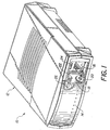
- FIG. 1 there is shown a compact film scanner 10 adapted for use with APS film cartridges to convert film images to digital images.
- the illustrated scanner comprises an outer casing 12 and a front bezel 14 which enclose an internal film drive chassis to be described in more detail below.
- the chassis is provided with an APS film cartridge chamber 16 for receiving a manually inserted APS film cartridge.
- a hinged, spring-loaded door 18 includes a locating device 20 which acts to engage the end of the inserted film cartridge (not shown) as the door is closed to aid in properly positioning the film cartridge in the chamber 16.
- a latch hook 22 on the door engages an internal latching mechanism 24 to lock the door in the closed position.
- a door release button 26 is actuated to unlock the latch mechanism allowing the door to spring open.
- An internal spring loaded mechanism (not shown) within the cartridge chamber forces the cartridge partially outward, allowing the user to grasp and remove the cartridge.
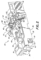
- the illustrated chassis comprises a lower frame 32 and an upper plate 34 which, when assembled as shown, define the film cartridge chamber 16, a film takeup chamber 36 and a film path 38 longitudinally extending between the two chambers.
- a film drive roller mechanism 40 including nip roller sets 52 and 53, is located near the film cartridge chamber 16.
- a pair of elongated apertures 41a, 41b are provided in upper plate 34 to allow access by magnetic read/write heads (not shown) to magnetic data tracks on the magnetic recording layer formed on the APS film as the film is driven along the film path, thereby enabling data transfer to and from the film magnetic layer, in known manner, as part of the film scanning process.
- Lower frame 32 is provided with depending skirt walls 39 that form a cavity in which is mounted imaging apparatus 50.
- One end of the imaging apparatus 50 comprises a film scanner end which is snap mounted into a film scanner opening 51 formed in the chassis 30.
- the film scanner end is straddled by film drive nip roller sets 52 and 53.
- the nip rollers are driven by a film drive stepper motor (not shown) which is directly coupled via drive gear 54 to main drive rollers beneath idler rollers 60 and, via main drive pulley 56, elastic drive belt 57 and slave drive pulley 58 to slave rollers beneath idler rollers 60'.
- Idler rollers 60 and 60' are held in place against their respect drive rollers by means of retention clamps 61 held under pressure by tension springs 62.
- the film scanner end of imaging apparatus 50 includes a pair of upstanding support arms 120 integrally formed on the imaging apparatus 50.
- the arms 120 comprise support mounts for an illuminant head assembly 200 (FIG. 3) constructed in accordance with the present invention as will be described more fully later.
- the other end of the imaging apparatus 50 comprises a sub-housing 64 which encloses a linear CCD photosensor device 66 (FIG. 3).
- the CCD is electrically mounted on a printed circuit board 63 but is physically supported directly from the sub-housing 64.
- the elongated housing of imaging apparatus 50 comprises the sole means of support of the CCD from the chassis frame 32.
- Spaced apart film guide pins 65a and 65b are located along one edge of the film path 38 to aid in accurately aligning magnet recording tracks on the APS film with the magnetic read/write heads positioned in the apertures 41a, 41b.
- the lower frame 32, upper plate 34 and housing body 72 are molded in the desired configurations out of a suitable, preferably blackened, 30% glass filled polycarbonate material held together by suitable fastening means (not shown), such as screws, snaps, adhesives and the like.
- suitable fastening means not shown
- Imaging apparatus 50 comprises a hollow, two-piece molded housing 70 having an upper, main body portion 72 and a separable, lower body portion 74.
- One end 80 of the housing 70 comprises a film scanning portion and the other end 82 comprises a light sensor portion.
- the film scanning end 80 includes an elongated light entry slot 83.
- a pair of film rails 84 are integrally molded onto the end of the imaging apparatus so as to bridge the slot 83 longitudinally in the direction of film path 38 to thereby define a film plane 86.
- the film rails 84 are spaced apart only slightly more than the lateral dimension of the negative image on the film strip so as to define a first scanning aperture 83a coincident with images on the film.
- the portions 83b and 83c extending beyond the rails 84 define secondary scan apertures, each of which is coincident with a respective edge region of the film.
- the other end 82 of the housing 70 includes sub-housing 64 which encloses linear CCD 66 mounted on printed wiring board 63.
- CCD 66 is supported from sub-housing 64 by means of radiation, preferably UV, curable adhesive "rivets" (not shown). Notch 89, and a similar notch on the far side of sub-housing 64, allow access by the UV radiation to the adhesive material inside the sub-housing 64 during the curing step.
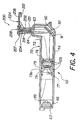
- the upper body portion 72 of the housing 70 is formed at right angles between the scanning end 80 and the photosensor end 82 to provide a compact structure enabling mounting of the film scanner 10 in a drive bay of a personal computer.
- a mirror 90 is mounted internally against ridges 91 formed inside the upper housing body 72 at a 45° angle to serve as reference datum surfaces for mounting of the mirror 90.
- the mirror is held in place against the ridges 91 by means of compressive spring fingers 92 formed on the housing lower body portion 74.
- a focusing lens assembly 76 is mounted in axial alignment with the light path from the scanning end 80 via the mirror 90 to the photosensor end 82.
- the focusing lens assembly 76 includes a focusing lens set 77 positioned within a cylindrical lens mount 78.
- the lens mount 78 is provided with a circumferential groove 79 for use in setting the focus position of the lens 76 during assembly and alignment of the imaging apparatus.
- the housing upper body portion 72 is provided with an adjustment slot 79a extending longitudinally of the housing 70. During the assembly process, a probe can be inserted through the slot 79a into engagement with groove 79 to move the lens mount 78 axially to focus the film plane 86 onto the CCD sensor 66.
- Flexible spring fingers with pressure pads 105 are molded into the lower body portion 74 to temporarily hold the lens mount 78 in place after the upper and lower body portions are assembled together until focusing alignment is completed, at which time the lens is permanently retained by adhesive injected through either one or both of the space bridging the spring fingers with the lens mount 78 and the lens adjustment slot 79a in the upper body portion 72, preferably the latter.
- Upper and lower body portions 72 and 74 when assembled together as shown, are held together by U-shaped spring clamp arms 106 on lower body portion 74 snapped over retention tabs 107 formed on upper body portion 72.
- a pair of support arms 120 that serve the dual functions of supporting the housing 70 on the chassis lower frame 32 and rigidly supporting a illuminant head assembly 200 in precise position over the light entry slot 83.
- the support arms are preferably integrally molded on the upper body 72 and are mirror images of each other.
- the lower portion of the support arm 120 includes a recessed portion 121 at the bottom of which there is provided a ramp 122 leading to the lower retention edge 124.
- the upper portions of each of the support arms 120 are provided with a channel 132 and notches 134, the purpose of which is explained below.
- the chassis lower frame 32 includes a pair of integrally molded, downwardly extending retention hook arms that are springlike and flex outwardly to permit insertion of the scanning end 80 of the illumination housing 70 onto the chassis lower frame 32.
- the chassis frame 32 is turned upside-down and the scanning end 80 is inserted into the opening 51.
- the hooks at the end of the retention arms initially fall into the recessed portions 121 and eventually engage the ramps 122 at which point the retention arms are flexed outwardly until the retention hooks grab and hold the housing assembly by engagement with the retention edges 124.
- the scanning end of the housing is now rigidly and securely captured between the retention arms.
- the lower frame 32 can be turned right side up for addition of the drive roller sets 52 and 53 and the upper chassis plate 34.
- the upper portions of the support arms extend above the chassis 30. As will be seen, this allows insertion of an illuminant head assembly 200 into the channels 132 of the support arms.
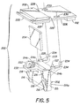
- the illuminant head assembly 200 comprises a main body 202, a planar light pipe 204, a printed circuit board 206 on which are mounted a linear array of red, green and blue LEDs 206a and additional LEDs 206b and 206c positioned at opposite ends of the linear array 206a.
- the linear array provides spectral red, green and blue illuminant for scanning of image areas on the film.
- the additional LEDs serve as respective sources of light for reading of bar code data (LED 206b) and for sensing of reference perforations in the film (LED 206c).
- LED 206b emits in the red spectrum.
- LED 206c is selected to emit in another color spectrum such as green or blue.
- a heat sink panel 208 is mounted on the opposite side of the circuit board from the LEDs 206a-206c.
- An apertured panel 207 is mounted over the LEDs on the circuit board and is provided with an elongated aperture 207a aligned with the linear LED array 206a and two smaller apertures 207b and 207c aligned with LEDs 206b and 206c, respectively.
- Panel 207 serves as a dam to retain a clear silicone sealant disposed in each of the apertures 207a-207c.
- the circuit board 206 also carries a connector 212 providing power connections to the LEDs from a microcontroller (not shown).
- the main body 202 made of a suitable highly reflective, white polycarbonate material, is provided with an elongated, planar light channel 214a into which light pipe 204 is inserted.
- Light pipe 204 is preferably made from a clear polymethylmethacrylate material loaded with a diffusion material such as barium sulfate at loadings of 0.1% to 1.0% by weight and preferably 0.25% by weight.
- the particle size of the barium sulfate ranges between 5-20 microns.
- the barium sulfate loaded light pipe 204 serves as the sole light diffusing agent for exposure of the LED light sources to the film being scanned.
- Smaller side channels 214b and 214c which do not have light pipes therein, serve to convey the illumination from LEDs 206b and 206c, respectively, to the bar coded data and reference perforations along the longitudinal edges of the film.
- the sides 215 of the main body 202 are shaped to fit into the channels 132 of the previously described support arms 120.
- Pointed crush ribs 216 which engage the edges 132a of the channels 132, ensure a tight fit of the body sides 215 in the channels as well as align edge surfaces 215a to edge surfaces 132c of the channels 132.
- Sides 215 of the main body are also provided with locking tabs 218 which engage notches 134 in the support arms to rigidly lock the head assembly into the support arm structure.
- the locking tabs 218 are integrally molded as part of the main body. The length width and depth of the locking tabs are such that, during assembly, the tabs deflect to allow insertion then spring back into position and contact the notches 134 preventing any movement up and out of the channels 134. This action maintains alignment of surfaces 217a and 217b (FIG. 6) to surfaces 132b at the bottom of the channels 132.
- Aperture panel 207 is provided with a semicircular shaped notch 235 which mates with the semicircular shaped support pad 232.
- Support pad 232 and notch 235 serve to initial locating means for assembly of the light sources to the main body.
- Support pad 233 is provided with a diamond shaped locating pin 226 and support pad 234 is provided with a circular locating pin 227. Each of the pins mate with corresponding locating holes 228 on the circuit board.
- both pins serve to set the alignment of the LEDs 206a, 206b and 206c to the elongate light channels 214a, 214b and 214c during assembly.
- snap locking hooks 224 on the main body gage mating locking holes 230 in the printed wiring board to securely hold the board in place on the main body.
- the arrangement described is a simple, practical self-aligning mounting arrangement for attaching the head assembly 200 in a secure and rigid manner to the imaging apparatus 50.
Abstract
Description
- The present invention relates generally to the field of photographic media image scanners. More specifically, the invention relates to small, low cost scanners adapted for use with personal computers by consumers who wish to generate digital images from processed film stored in a film cartridge as in the case of the Advanced Photo System (APS) film.
- Users of personal home computers are increasingly loading digital image files into their computer for viewing, communicating images through the Internet and printing hardcopies on personal color printers. With the introduction of the Advanced Photo System, which stores processed film in the film cartridge, there is a growing interest in being able to scan and digitize images from the stored film for use on the personal computer. Such a scanner should not only be low cost, to obtain broad acceptance as a consumer product, but also needs to be compact in size to be able to fit into a standard disk drive bay on a personal computer.
- In designing a film scanner for this type of application, it is important to have a design that uses a minimum of parts, is simple to manufacture and yet creates and maintains critical, micro-precision alignment of the photosensor with the film plane in the scan gate. The design of the present invention fully meets these objectives.
- In accordance with one aspect of the invention therefore, there is provided an illuminant head assembly for a photographic media image scanner which comprises a linear light source and a main body having a first elongate planar light conducting channel aligned with the linear light source, wherein the light conducting channel includes a planar light pipe therein, the light pipe having a light diffusion material dispersed throughout the light pipe.
- In accordance with another aspect of the invention, an illuminant head assembly is provided for a film scanner of the type having a scan gate and a pair of support arms on opposite sides of the scan gate, at least one of the support arms having a notch formed therein. In this aspect of the invention, the head assembly comprises a linear light source and a main body having a first elongate planar light conducting channel aligned with the linear light source, the light conducting channel including a planar light pipe therein, the light pipe having a light diffusion material dispersed throughout the light pipe. The main body has opposite side portions adapted to mate with the support arms of the film scanner. At least one of the side portions has a spring finger positioned to mate and lock into the notch in the support arms when the illuminant assembly is mounted into position on the support arms.
- These and other aspects, objects, features and advantages of the present invention will be more clearly understood and appreciated from a review of the following detailed description of the preferred embodiments and appended claims, and by reference to the accompanying drawings. In the drawings:
- FIG. 1 is an isometric view showing a film scanner embodying the present invention;
- FIG. 2 is a perspective view of a film scanner chassis embodying the present invention;
- FIG. 3 is a partially exploded perspective view of an imaging apparatus and illumination head embodying principles of the present invention;
- FIG. 4 is a cross section side elevation view of the imaging apparatus and illumination head of FIG. 3;
- FIG. 5 is an exploded perspective view from above of the illumination head shown in FIGS. 3 and 4; and
- FIG. 6 is an exploded perspective view from below of the illumination head shown in FIGS. 3 and 4.
-
- In FIG. 1, there is shown a
compact film scanner 10 adapted for use with APS film cartridges to convert film images to digital images. The illustrated scanner comprises anouter casing 12 and afront bezel 14 which enclose an internal film drive chassis to be described in more detail below. The chassis is provided with an APSfilm cartridge chamber 16 for receiving a manually inserted APS film cartridge. A hinged, spring-loadeddoor 18 includes a locatingdevice 20 which acts to engage the end of the inserted film cartridge (not shown) as the door is closed to aid in properly positioning the film cartridge in thechamber 16. Alatch hook 22 on the door engages aninternal latching mechanism 24 to lock the door in the closed position. When it is desired to remove the film cartridge, adoor release button 26 is actuated to unlock the latch mechanism allowing the door to spring open. An internal spring loaded mechanism (not shown) within the cartridge chamber forces the cartridge partially outward, allowing the user to grasp and remove the cartridge. - Referring to FIG 2, a general description of the internal
film drive chassis 30 of thescanner 10 is presented here. The illustrated chassis comprises alower frame 32 and anupper plate 34 which, when assembled as shown, define thefilm cartridge chamber 16, afilm takeup chamber 36 and afilm path 38 longitudinally extending between the two chambers. A filmdrive roller mechanism 40, includingnip roller sets film cartridge chamber 16. A pair ofelongated apertures 41a, 41b are provided inupper plate 34 to allow access by magnetic read/write heads (not shown) to magnetic data tracks on the magnetic recording layer formed on the APS film as the film is driven along the film path, thereby enabling data transfer to and from the film magnetic layer, in known manner, as part of the film scanning process.Lower frame 32 is provided with dependingskirt walls 39 that form a cavity in which is mountedimaging apparatus 50. - One end of the
imaging apparatus 50, as will be seen in reference to FIG. 3, comprises a film scanner end which is snap mounted into afilm scanner opening 51 formed in thechassis 30. The film scanner end is straddled by film drivenip roller sets drive gear 54 to main drive rollers beneathidler rollers 60 and, viamain drive pulley 56,elastic drive belt 57 andslave drive pulley 58 to slave rollers beneath idler rollers 60'. Idlerrollers 60 and 60' are held in place against their respect drive rollers by means ofretention clamps 61 held under pressure bytension springs 62. The film scanner end ofimaging apparatus 50 includes a pair ofupstanding support arms 120 integrally formed on theimaging apparatus 50. Thearms 120 comprise support mounts for an illuminant head assembly 200 (FIG. 3) constructed in accordance with the present invention as will be described more fully later. The other end of theimaging apparatus 50 comprises asub-housing 64 which encloses a linear CCD photosensor device 66 (FIG. 3). The CCD is electrically mounted on a printedcircuit board 63 but is physically supported directly from thesub-housing 64. The elongated housing ofimaging apparatus 50 comprises the sole means of support of the CCD from thechassis frame 32. Spaced apartfilm guide pins film path 38 to aid in accurately aligning magnet recording tracks on the APS film with the magnetic read/write heads positioned in theapertures 41a, 41b. Thelower frame 32,upper plate 34 andhousing body 72 are molded in the desired configurations out of a suitable, preferably blackened, 30% glass filled polycarbonate material held together by suitable fastening means (not shown), such as screws, snaps, adhesives and the like. The use of this material is highly beneficial in this application because of its stability in the presence of humidity and temperature changes which is particularly important in this configuration wherein the photosensor relies on the housing as the sole means of support from the scanning film plane. - Referring jointly to FIGS. 3, 3a and 4, details of the
imaging apparatus 50 will be described.Imaging apparatus 50 comprises a hollow, two-piece moldedhousing 70 having an upper,main body portion 72 and a separable,lower body portion 74. Oneend 80 of thehousing 70 comprises a film scanning portion and theother end 82 comprises a light sensor portion. Thefilm scanning end 80 includes an elongatedlight entry slot 83. As best seen in FIG. 3a, a pair offilm rails 84 are integrally molded onto the end of the imaging apparatus so as to bridge theslot 83 longitudinally in the direction offilm path 38 to thereby define afilm plane 86. For this purpose, thefilm rails 84 are spaced apart only slightly more than the lateral dimension of the negative image on the film strip so as to define a first scanning aperture 83a coincident with images on the film. Theportions rails 84 define secondary scan apertures, each of which is coincident with a respective edge region of the film. Theother end 82 of thehousing 70 includessub-housing 64 which encloseslinear CCD 66 mounted on printedwiring board 63.CCD 66 is supported fromsub-housing 64 by means of radiation, preferably UV, curable adhesive "rivets" (not shown).Notch 89, and a similar notch on the far side ofsub-housing 64, allow access by the UV radiation to the adhesive material inside thesub-housing 64 during the curing step. - The
upper body portion 72 of thehousing 70 is formed at right angles between the scanningend 80 and thephotosensor end 82 to provide a compact structure enabling mounting of thefilm scanner 10 in a drive bay of a personal computer. To this end, amirror 90 is mounted internally againstridges 91 formed inside theupper housing body 72 at a 45° angle to serve as reference datum surfaces for mounting of themirror 90. The mirror is held in place against theridges 91 by means ofcompressive spring fingers 92 formed on the housinglower body portion 74. Internally ofhousing body portions mirror 90 andCCD 66, a focusinglens assembly 76 is mounted in axial alignment with the light path from thescanning end 80 via themirror 90 to thephotosensor end 82. The focusinglens assembly 76 includes a focusinglens set 77 positioned within acylindrical lens mount 78. Thelens mount 78 is provided with acircumferential groove 79 for use in setting the focus position of thelens 76 during assembly and alignment of the imaging apparatus. To this end, the housingupper body portion 72 is provided with anadjustment slot 79a extending longitudinally of thehousing 70. During the assembly process, a probe can be inserted through theslot 79a into engagement withgroove 79 to move thelens mount 78 axially to focus thefilm plane 86 onto theCCD sensor 66. Flexible spring fingers withpressure pads 105 are molded into thelower body portion 74 to temporarily hold thelens mount 78 in place after the upper and lower body portions are assembled together until focusing alignment is completed, at which time the lens is permanently retained by adhesive injected through either one or both of the space bridging the spring fingers with thelens mount 78 and thelens adjustment slot 79a in theupper body portion 72, preferably the latter. Upper andlower body portions spring clamp arms 106 onlower body portion 74 snapped overretention tabs 107 formed onupper body portion 72. - Integrally formed on the outer lateral sides of the
scanning end 80 of thehousing 70 are a pair ofsupport arms 120 that serve the dual functions of supporting thehousing 70 on the chassislower frame 32 and rigidly supporting ailluminant head assembly 200 in precise position over thelight entry slot 83. The support arms are preferably integrally molded on theupper body 72 and are mirror images of each other. The lower portion of thesupport arm 120 includes a recessedportion 121 at the bottom of which there is provided aramp 122 leading to thelower retention edge 124. The upper portions of each of thesupport arms 120 are provided with achannel 132 andnotches 134, the purpose of which is explained below. The chassislower frame 32 includes a pair of integrally molded, downwardly extending retention hook arms that are springlike and flex outwardly to permit insertion of thescanning end 80 of theillumination housing 70 onto the chassislower frame 32. During assembly of theimaging apparatus 50 to thelower chassis frame 32, thechassis frame 32 is turned upside-down and thescanning end 80 is inserted into theopening 51. During this snap-in step, the hooks at the end of the retention arms initially fall into the recessedportions 121 and eventually engage theramps 122 at which point the retention arms are flexed outwardly until the retention hooks grab and hold the housing assembly by engagement with the retention edges 124. The scanning end of the housing is now rigidly and securely captured between the retention arms. Once this is completed, thelower frame 32 can be turned right side up for addition of the drive roller sets 52 and 53 and theupper chassis plate 34. As can best be seen in FIG. 2, the upper portions of the support arms extend above thechassis 30. As will be seen, this allows insertion of anilluminant head assembly 200 into thechannels 132 of the support arms. - Referring jointly to FIGS. 3-6, the
illuminant head assembly 200 of the present invention will now be described. Theilluminant head assembly 200 comprises amain body 202, a planarlight pipe 204, a printedcircuit board 206 on which are mounted a linear array of red, green andblue LEDs 206a andadditional LEDs linear array 206a. The linear array provides spectral red, green and blue illuminant for scanning of image areas on the film. The additional LEDs serve as respective sources of light for reading of bar code data (LED 206b) and for sensing of reference perforations in the film (LED 206c). Preferably,LED 206b emits in the red spectrum. However, since Dmin density of the film is almost transparent in the red spectrum,LED 206c is selected to emit in another color spectrum such as green or blue. Aheat sink panel 208 is mounted on the opposite side of the circuit board from theLEDs 206a-206c. Anapertured panel 207 is mounted over the LEDs on the circuit board and is provided with anelongated aperture 207a aligned with thelinear LED array 206a and twosmaller apertures LEDs Panel 207 serves as a dam to retain a clear silicone sealant disposed in each of theapertures 207a-207c. Thecircuit board 206 also carries aconnector 212 providing power connections to the LEDs from a microcontroller (not shown). - The
main body 202, made of a suitable highly reflective, white polycarbonate material, is provided with an elongated, planar light channel 214a into whichlight pipe 204 is inserted.Light pipe 204 is preferably made from a clear polymethylmethacrylate material loaded with a diffusion material such as barium sulfate at loadings of 0.1% to 1.0% by weight and preferably 0.25% by weight. The particle size of the barium sulfate ranges between 5-20 microns. The balancing of the interaction of the length of the light pipe, the loading of barium sulfate and the particle size of the barium sulfate allow for a diffuse light output at the bottom outlet of the elongated light channel 214a without the need for any special surface finish on the light pipe or the addition of a separate diffusion component. Thus the barium sulfate loadedlight pipe 204 serves as the sole light diffusing agent for exposure of the LED light sources to the film being scanned.Smaller side channels LEDs sides 215 of themain body 202 are shaped to fit into thechannels 132 of the previously describedsupport arms 120.Pointed crush ribs 216, which engage theedges 132a of thechannels 132, ensure a tight fit of the body sides 215 in the channels as well as alignedge surfaces 215a to edgesurfaces 132c of thechannels 132. By dimensioning and controlling, during manufacture, the position ofsurface 215a to the elongate light channel 214a, the alignment of the elongate light channel 214a to the elongatelight entry slot 83 is maintained without subsequent adjustment. -
Sides 215 of the main body are also provided with lockingtabs 218 which engagenotches 134 in the support arms to rigidly lock the head assembly into the support arm structure. The lockingtabs 218 are integrally molded as part of the main body. The length width and depth of the locking tabs are such that, during assembly, the tabs deflect to allow insertion then spring back into position and contact thenotches 134 preventing any movement up and out of thechannels 134. This action maintains alignment ofsurfaces 217a and 217b (FIG. 6) tosurfaces 132b at the bottom of thechannels 132. The parts of the head assembly are easily snapped together by slippingend 220 of the printed wiring board under acapture hook 222 formed on themain body 202 and rotating the printed wiring board down until the under surface of the printed wiring board rests on the upper surfaces ofsupport pads Aperture panel 207 is provided with a semicircular shapednotch 235 which mates with the semicircular shapedsupport pad 232.Support pad 232 and notch 235 serve to initial locating means for assembly of the light sources to the main body.Support pad 233 is provided with a diamond shaped locatingpin 226 andsupport pad 234 is provided with acircular locating pin 227. Each of the pins mate with corresponding locatingholes 228 on the circuit board. As such, both pins serve to set the alignment of theLEDs light channels mating locking holes 230 in the printed wiring board to securely hold the board in place on the main body. The arrangement described is a simple, practical self-aligning mounting arrangement for attaching thehead assembly 200 in a secure and rigid manner to theimaging apparatus 50. - It will be appreciated from the foregoing description that what has been described is an illuminant head assembly of simple and compact design that is provided with snap lock features that facilitate rapid assembly and that precisely and rigidly positions the LED light elements in place over the scanning
aperture 83 of the imaging aperture without the requirement for additional fasteners. The use of an elongated light pipe with diffusion material in the light pipe simplifies the cost and complexity of the head design by eliminating the need for a separate diffusion element at the outlet of elongated channel 214. Additionally, the incorporation of spectrally discrete, for example, red, green and blue, separate illumination elements enables independent adjustment of the spectral components of the film scanning illumination.
Claims (10)
- An illuminant head assembly 200 for a photographic media image scanner 10 characterized by:a linear light source 206a; anda main body 202 having a first elongate planar light conducting channel 214a aligned with the linear light source, the light conducting channel including a planar light pipe 204 therein, the light pipe having a light diffusion material dispersed throughout the light pipe as a sole light diffusing agent.
- The illuminant head assembly of claim 1 wherein the scanner comprises a film drive chassis 30 with a film path 38 having an elongate first scanning aperture 83a coincident with image frames on the film and a second scan aperture 83b/83c coincident with an edge region of the film, the illuminant head assembly further comprising the planar light conducting channel 214a having a length substantially coincident with the length of the first scanning aperture, and having a second light conducting channel 214b/214c adapted to be in alignment with the second scan aperture.
- The illuminant head assembly of claim 1, wherein the scanner comprises a film drive chassis 30 with a film path 38 having an elongate first scanning aperture 83a coincident with image frames on the film and first and second scan apertures 83b, 83c coincident with opposite edge regions of the film, the illuminant head assembly further comprising the main body having a length substantially coincident with the length of the first scanning aperture 83a, and having first and second light conducting channels 214b, 214c adapted to be in alignment with the first and second scan apertures 83b, 83c, respectively.
- The illuminant head assembly of claim 1, wherein the diffusion material consists of barium sulfate.
- The illuminant head assembly of claim 4 wherein the light pipe has a barium sulfate loading of within a range of 0.1%-1.0% by weight and the barium sulfate has a particle size in the range of 5-20 microns.
- The illuminant head assembly of claim 5 wherein the barium sulfate loading is 0.25% by weight.
- The illuminant head assembly of claim 1 wherein the linear light source includes a linear array of spectrally distinct LED light sources extending at least across the elongate light conducting channel.
- The illuminant head assembly of claim 1, the scanner having a scan gate and a pair of support arms 120 on opposite sides of the scan gate, at least one of the support arms having a notch 134 formed therein; the head assembly further characterized by:the main body having opposite side portions 215 adapted to mate with the support arms and at least one of the side portions having a spring finger 218 positioned to mate and lock into the notch when the illuminant assembly is mounted into position on the support arms.
- The illuminant head assembly of claim 8 wherein the film scanner support arms have elongated channels 132 formed therein and the main body side portions 215 are shaped to mate with the channels, the side portions including a plurality of crush ribs 216 positioned to engage edges 132a of the channels to hold the main body rigidly within and aligned to the channels when the head assembly is mounted on the support arms.
- The illuminant head assembly of claim 8 wherein the linear light source comprises a substrate 206 and a line of spectrally distinct light sources 206a, 206b, 206c mounted on the substrate, the substrate having a plurality of apertures therein;the main body includes a plurality of support pads 232-234 providing reference datum support surfaces for the light source substrate, a substrate retention hook 222 adjacent one of the support pads 232, a further pair of the support pads 233, 234 having reference datum locating posts 226, 227 extending from the reference datum support surfaces thereof in alignment with a corresponding pair of the apertures in the substrate, and at least one further locking hook 224 adapted to engage the substrate when mounted on the reference datum support surface thereby to hold the substrate rigidly in position on the main body with the linear light source in alignment with the elongated light channel.
Applications Claiming Priority (2)
| Application Number | Priority Date | Filing Date | Title |
|---|---|---|---|
| US09/084,062 US6271941B1 (en) | 1998-05-22 | 1998-05-22 | Illuminant head assembly for a photographic film image scanner |
| US84062 | 1998-05-22 |
Publications (2)
| Publication Number | Publication Date |
|---|---|
| EP0959609A2 true EP0959609A2 (en) | 1999-11-24 |
| EP0959609A3 EP0959609A3 (en) | 2001-09-12 |
Family
ID=22182653
Family Applications (1)
| Application Number | Title | Priority Date | Filing Date |
|---|---|---|---|
| EP99201488A Withdrawn EP0959609A3 (en) | 1998-05-22 | 1999-05-12 | Illuminant head assembly for a photographic film image scanner |
Country Status (3)
| Country | Link |
|---|---|
| US (1) | US6271941B1 (en) |
| EP (1) | EP0959609A3 (en) |
| JP (1) | JP2000013677A (en) |
Cited By (2)
| Publication number | Priority date | Publication date | Assignee | Title |
|---|---|---|---|---|
| EP1158760A1 (en) * | 2000-05-26 | 2001-11-28 | GRETAG IMAGING Trading AG | Photographic image acquisition device using leds |
| DE102008025194A1 (en) | 2008-05-27 | 2009-12-03 | Wimmer, Michaela | Method for homogeneous and linear transillumination of transparent, analog information media, involves coupling light emitted from light source in plate shaped light conductor |
Families Citing this family (1)
| Publication number | Priority date | Publication date | Assignee | Title |
|---|---|---|---|---|
| TW446257U (en) * | 1999-12-18 | 2001-07-11 | Umax Data Systems Inc | Improved device of the light source of scanner for the usable range in the axial direction |
Citations (2)
| Publication number | Priority date | Publication date | Assignee | Title |
|---|---|---|---|---|
| US4485302A (en) * | 1978-12-26 | 1984-11-27 | Fuji Photo Film Co., Ltd. | Radiation image read out device |
| EP0481515A2 (en) * | 1990-10-19 | 1992-04-22 | National Computer Systems, Inc. | Illumination system for scanner |
Family Cites Families (29)
| Publication number | Priority date | Publication date | Assignee | Title |
|---|---|---|---|---|
| US5515136A (en) | 1949-09-21 | 1996-05-07 | Fuji Photo Film Co., Ltd. | Image recording apparatus |
| US3217594A (en) | 1963-02-27 | 1965-11-16 | Simmon Brothers Inc | Photographic printer and enlarger and light mixing device therefor |
| US3532873A (en) | 1967-10-27 | 1970-10-06 | Ford Motor Co | Apparatus for monitoring light source operation |
| US3825336A (en) | 1973-01-04 | 1974-07-23 | Polaroid Corp | Variable color photographic lighting source |
| US3825335A (en) | 1973-01-04 | 1974-07-23 | Polaroid Corp | Variable color photographic lighting system |
| GB1494424A (en) | 1975-03-24 | 1977-12-07 | Xerox Corp | Copying machine |
| US4125315A (en) | 1976-07-28 | 1978-11-14 | Vivitar Corporation | Light mixing device |
| US4129372A (en) | 1976-08-17 | 1978-12-12 | Vivitar Corporation | Light mixing apparatus and photographic enlarger embodying same |
| US4255042A (en) | 1979-03-26 | 1981-03-10 | International Business Machines Corporation | Light pipe for accurate erasure of photoconductor charge |
| US4240738A (en) | 1979-06-14 | 1980-12-23 | Vivitar Corporation | Light mixing system for a photographic enlarger |
| US4342511A (en) | 1980-08-20 | 1982-08-03 | International Business Machines Corporation | Illumination system having an efficient light guide |
| US4783700A (en) * | 1986-06-10 | 1988-11-08 | Canon Kabushiki Kaisha | Image sensor unit and image reading apparatus having the unit |
| JPH073891B2 (en) | 1987-06-09 | 1995-01-18 | 株式会社東芝 | Light emitting element array |
| US4954931A (en) | 1988-07-08 | 1990-09-04 | Parker Hannifin Corporation | Linear diffuse light source |
| US4899040A (en) | 1988-09-08 | 1990-02-06 | Eastman Kodak Company | Light-conditioning apparatus for an image scanner illumination system |
| US5031078A (en) | 1989-08-28 | 1991-07-09 | Vari-Lite, Inc. | Additive color mixing system with variable hue and saturation light sources |
| JPH03132705A (en) | 1989-10-19 | 1991-06-06 | Brother Ind Ltd | Optical waveguide array and production thereof |
| US5323300A (en) | 1992-07-06 | 1994-06-21 | Mccrary Charles F | Jewelry lighting device |
| DE69418499T2 (en) | 1993-02-01 | 2000-02-10 | Tosoh Corp | Backlight device |
| US5327328A (en) | 1993-05-28 | 1994-07-05 | Dialight Corporation | Lightpipe and lightpipe array for redirecting light from a surface mount led |
| US5504317A (en) | 1994-01-05 | 1996-04-02 | Opticon, Inc. | Optical reader |
| US5535021A (en) * | 1994-06-06 | 1996-07-09 | Microtek International, Inc. | Scanner light diffuser |
| US5414489A (en) | 1994-06-22 | 1995-05-09 | Eastman Kodak Company | Light pipe spectral filter |
| US5575549A (en) * | 1994-08-12 | 1996-11-19 | Enplas Corporation | Surface light source device |
| US5764493A (en) * | 1995-12-11 | 1998-06-09 | Liao; Chun-Chi | Palm top image scanner back lighting device |
| JPH09294188A (en) * | 1996-04-26 | 1997-11-11 | Konica Corp | Film scanner |
| US5726790A (en) * | 1996-07-19 | 1998-03-10 | Mustek Systems, Inc. | Converter for converting a reflection type scanner to a transparence type scanner |
| US5798849A (en) * | 1996-11-05 | 1998-08-25 | Mustek Systems Inc. | Multilevel light source device |
| US5923411A (en) * | 1997-06-27 | 1999-07-13 | Eastman Kodak Company | Photographic printer with mechanism for placing contact print slide at paper print gate |
-
1998
- 1998-05-22 US US09/084,062 patent/US6271941B1/en not_active Expired - Fee Related
-
1999
- 1999-04-21 JP JP11114075A patent/JP2000013677A/en active Pending
- 1999-05-12 EP EP99201488A patent/EP0959609A3/en not_active Withdrawn
Patent Citations (2)
| Publication number | Priority date | Publication date | Assignee | Title |
|---|---|---|---|---|
| US4485302A (en) * | 1978-12-26 | 1984-11-27 | Fuji Photo Film Co., Ltd. | Radiation image read out device |
| EP0481515A2 (en) * | 1990-10-19 | 1992-04-22 | National Computer Systems, Inc. | Illumination system for scanner |
Cited By (2)
| Publication number | Priority date | Publication date | Assignee | Title |
|---|---|---|---|---|
| EP1158760A1 (en) * | 2000-05-26 | 2001-11-28 | GRETAG IMAGING Trading AG | Photographic image acquisition device using leds |
| DE102008025194A1 (en) | 2008-05-27 | 2009-12-03 | Wimmer, Michaela | Method for homogeneous and linear transillumination of transparent, analog information media, involves coupling light emitted from light source in plate shaped light conductor |
Also Published As
| Publication number | Publication date |
|---|---|
| EP0959609A3 (en) | 2001-09-12 |
| US6271941B1 (en) | 2001-08-07 |
| JP2000013677A (en) | 2000-01-14 |
Similar Documents
| Publication | Publication Date | Title |
|---|---|---|
| US5946031A (en) | Electronic still camera with printing capability | |
| US6178016B1 (en) | Imaging apparatus for a photographic film image scanner | |
| US5546144A (en) | Transparency holder | |
| EP0959609A2 (en) | Illuminant head assembly for a photographic film image scanner | |
| KR100279900B1 (en) | Image input device | |
| US5164763A (en) | Instant photocopying apparatus | |
| JPH08172512A (en) | Lighting image-forming composite module and original reader using it | |
| US20030202093A1 (en) | Film scanner | |
| US20080043216A1 (en) | Film holder and film scan module using the same and multi-functional peripheral using the same | |
| US6126335A (en) | Film holder and image reading device | |
| JP2004271580A (en) | Image scanner | |
| JP3824399B2 (en) | Data imprinting device | |
| JPH01284067A (en) | Reader | |
| JPH10327279A (en) | Film holding member | |
| JPH0452742Y2 (en) | ||
| JP3642856B2 (en) | Image reading device | |
| JP2929404B2 (en) | Image forming device | |
| JPH07123216A (en) | Picture input device | |
| JP2003043596A (en) | Picture reader | |
| JPH01105230A (en) | Film image reader | |
| JP2004271581A (en) | Image scanner | |
| JPH0611763A (en) | Data recording and reproducing device | |
| JPH1028193A (en) | Picture input device | |
| JPH09160137A (en) | Slide holding device | |
| JPH07123210A (en) | Picture reader |
Legal Events
| Date | Code | Title | Description |
|---|---|---|---|
| PUAI | Public reference made under article 153(3) epc to a published international application that has entered the european phase |
Free format text: ORIGINAL CODE: 0009012 |
|
| AK | Designated contracting states |
Kind code of ref document: A2 Designated state(s): AT BE CH CY DE DK ES FI FR GB GR IE IT LI LU MC NL PT SE Kind code of ref document: A2 Designated state(s): DE FR GB |
|
| AX | Request for extension of the european patent |
Free format text: AL;LT;LV;MK;RO;SI |
|
| PUAL | Search report despatched |
Free format text: ORIGINAL CODE: 0009013 |
|
| AK | Designated contracting states |
Kind code of ref document: A3 Designated state(s): AT BE CH CY DE DK ES FI FR GB GR IE IT LI LU MC NL PT SE |
|
| AX | Request for extension of the european patent |
Free format text: AL;LT;LV;MK;RO;SI |
|
| 17P | Request for examination filed |
Effective date: 20020202 |
|
| AKX | Designation fees paid |
Free format text: DE FR GB |
|
| STAA | Information on the status of an ep patent application or granted ep patent |
Free format text: STATUS: THE APPLICATION HAS BEEN WITHDRAWN |
|
| 18W | Application withdrawn |
Effective date: 20041021 |