EP0959556B1 - Feldorientiertes Regelungssystem für Asynchronmotoren mit minimaler Energie - Google Patents
Feldorientiertes Regelungssystem für Asynchronmotoren mit minimaler Energie Download PDFInfo
- Publication number
- EP0959556B1 EP0959556B1 EP99410069A EP99410069A EP0959556B1 EP 0959556 B1 EP0959556 B1 EP 0959556B1 EP 99410069 A EP99410069 A EP 99410069A EP 99410069 A EP99410069 A EP 99410069A EP 0959556 B1 EP0959556 B1 EP 0959556B1
- Authority
- EP
- European Patent Office
- Prior art keywords
- torque
- motor
- nominal
- flux
- flow
- Prior art date
- Legal status (The legal status is an assumption and is not a legal conclusion. Google has not performed a legal analysis and makes no representation as to the accuracy of the status listed.)
- Expired - Lifetime
Links
- 230000004907 flux Effects 0.000 title claims description 20
- 238000001914 filtration Methods 0.000 claims description 11
- 230000033228 biological regulation Effects 0.000 claims description 8
- 238000012546 transfer Methods 0.000 claims description 5
- 230000007423 decrease Effects 0.000 claims description 2
- 238000012545 processing Methods 0.000 description 6
- 238000005265 energy consumption Methods 0.000 description 5
- 230000003247 decreasing effect Effects 0.000 description 2
- 238000013459 approach Methods 0.000 description 1
- 238000013461 design Methods 0.000 description 1
- 238000010586 diagram Methods 0.000 description 1
- 230000006698 induction Effects 0.000 description 1
- 238000012360 testing method Methods 0.000 description 1
- 230000003313 weakening effect Effects 0.000 description 1
Images

Classifications
-
- H—ELECTRICITY
- H02—GENERATION; CONVERSION OR DISTRIBUTION OF ELECTRIC POWER
- H02P—CONTROL OR REGULATION OF ELECTRIC MOTORS, ELECTRIC GENERATORS OR DYNAMO-ELECTRIC CONVERTERS; CONTROLLING TRANSFORMERS, REACTORS OR CHOKE COILS
- H02P21/00—Arrangements or methods for the control of electric machines by vector control, e.g. by control of field orientation
- H02P21/14—Estimation or adaptation of machine parameters, e.g. flux, current or voltage
- H02P21/141—Flux estimation
-
- H—ELECTRICITY
- H02—GENERATION; CONVERSION OR DISTRIBUTION OF ELECTRIC POWER
- H02P—CONTROL OR REGULATION OF ELECTRIC MOTORS, ELECTRIC GENERATORS OR DYNAMO-ELECTRIC CONVERTERS; CONTROLLING TRANSFORMERS, REACTORS OR CHOKE COILS
- H02P21/00—Arrangements or methods for the control of electric machines by vector control, e.g. by control of field orientation
- H02P21/06—Rotor flux based control involving the use of rotor position or rotor speed sensors
- H02P21/08—Indirect field-oriented control; Rotor flux feed-forward control
Definitions
- the present invention relates to an asynchronous motor control system, and more specifically to a controlled flow control system or FOC (Field Oriented Control).
- FOC Field Oriented Control
- the figure 1 schematically represents a conventional directed flow control system for an asynchronous motor 10.
- An oriented flow control device 12 drives the motor 10 via a pulse width modulator 14.
- the control device 12 uses the current I and the speed rotation of the motor, which are supplied by sensors 16.
- the control device 12 receives two setpoints, namely the desired torque T and the desired flow ⁇ .
- said constant flux, the flow ⁇ is chosen at its nominal value and it acts on the setpoint torque T to obtain the desired operation.
- a control loop determines the torque setpoint T as a function of the difference between the setpoint speed and the measured speed ⁇ .
- a flow setpoint equal to the nominal flow is inadequate because it causes a saturation of the pulse width modulator 14 leading to a non-linear reaction thereof to the control device 12.
- the figure 2 illustrates, on an arbitrary scale, an evolution of the maximum setpoint flow as a function of the speed of rotation ⁇ to avoid saturation phenomena.
- the reference flow is equal to the nominal flow ⁇ n .
- the setpoint flow follows a decreasing curve which corresponds to the saturation input limit of the pulse width modulator.
- a constant flow control system of the type of the figure 1 possibly used with a flux attenuation circuit according to the figure 2 , provides optimum performance of the engine 10 under nominal operating conditions.
- the motors often operate in conditions that are far from the nominal conditions, in particular under-revs. The efficiency of the engine becomes particularly bad.
- the figure 3 represents a solution to optimize the performance at any engine speed, as described in the article entitled " Robust Torque Control Design for Induction Motors: the Minimal Energy Approach ", by C. Canudas of Wit and I. Seleme, published in Automatica, Volume 33, No. 1, pp. 63-79, 1997 .
- This solution is based on the control system with flow-oriented control of the figure 1 .
- the oriented flow control device 12 is here provided to receive the derivative ⁇ 'as a function of time of the reference flow ⁇ .
- Such a system provides excellent results irrespective of the speed of the engine 10, provided that this regime is quasi-stationary. If the torque setpoint T varies too rapidly, the system performance degrades and even becomes worse than that of a constant flow system.
- An object of the present invention is to provide a particularly simple control system for an asynchronous motor, which allows operation in optimal conditions, regardless of engine speed and the rate of change of the setpoint.
- the present invention provides an asynchronous motor control system by flow-oriented control, responsive to a torque setpoint and a flow setpoint.
- the flow setpoint is supplied from the torque setpoint by an operator performing low-pass filtering of the first order and calculating the square root of the result of the filtering.
- the operator also performs, before filtering, a limitation of excursion of the torque setpoint between a minimum threshold and a maximum threshold.
- the operator also performs a limitation of the result of the square root at a maximum value which is constant up to a nominal value of the motor rotation speed, then decreasing as a function of the rotational speed, and then a second first-order low-pass filtering.
- s is the Laplace operator
- R r is the motor rotor resistance
- T n is the motor nominal torque
- n is the number of motor poles
- ⁇ n is the nominal motor flux
- the system also reacts to the derivative with respect to the time of the flow setpoint.
- said maximum threshold is the nominal torque of the motor and said minimum threshold is of the order of 4% of the nominal torque.
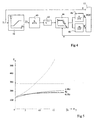
- a processing line provides, from a torque setpoint T, a flow setpoint ⁇ to an oriented flow control device 12 incorporated into a system of the type of the figure 1 .
- the essential function of this processing chain is to carry out low-pass filtering of the first order on the setpoint torque T and to take, as a reference flow, the square root of the result of the filtering.
- These transactions are materialized at the figure 4 by a filter 40 followed by a square root calculation circuit 42.
- Other elements, not yet described, of the processing chain may be omitted under certain operating conditions of the system.
- the transfer function of the filter 40 is expressed by b / (a + s), where a and b are constants and s is the Laplace operator.
- the figure 5 is intended to illustrate the performance gain obtained with a system according to the invention. It represents energy consumption curves as a function of the speed of variation of the torque reference T.
- the tests were carried out with a sinusoidal torque setpoint varying between -10% and + 10% of the nominal torque of the motor and whose the frequency ⁇ T is reported in radians per second.
- a 7.5 kW motor with a 0.22 kg ⁇ m 2 inertia load was used.
- the energy consumed E is expressed in Joules over 4 s.
- a dashed curve represents the energy consumed using a conventional constant-flow system of the figure 1 .
- the dashed line represents the energy consumed using a conventional optimized system of the type of figure 3 .
- a family of curves in solid line represents the energy consumed using a control system according to the invention.
- the constant flow system produces a substantially constant energy consumption (dashed) of relatively high value.
- the energy consumption (solid line) produced using a control system according to the invention slowly increases from the optimal value of the stationary regime and flattens at high frequencies of the target torque, so as to remain significantly lower the energy consumed with both conventional control systems.
- the optimum values of the constants a and b, provided above, depend on the resistance R r of the motor rotor. However, this resistance varies in particular according to the engine temperature. It is common to observe variations of ⁇ 50% around the nominal value.
- the family of curves in solid lines of the figure 5 illustrates the range of variation of the energy consumption according to the variation of the resistance of the rotor.
- the processing chain of the figure 4 is preferably completed by the elements described below.
- a conventional flux loss circuit 44 described in connection with the figure 2 , is disposed after the circuit 42 of square root calculation. This circuit 44 requires a speed information ⁇ supplied by the sensors 16 of the conventional control system of the figure 1 .
- the flux attenuation circuit 44 decreases the output signal of the circuit 42 progressively as a function of the speed beyond the saturation limit speed of the pulse width modulator.
- the flux setpoint ⁇ supplied to the oriented flow control device 12 arrives by a first-order low-pass filter 46 which receives the output of the flux-weakening circuit 44.
- the directed-flow control device 12 may be provided, as at the figure 3 to take into account the derivative ⁇ 'of the flux setpoint ⁇ . This derivative is provided by a filter 48 also receiving the output of the circuit 44. If the transfer function of the filter 46 is expressed by c / (c + s), where c is a constant and is the Laplace operator, the Transfer function of filter 48 is expressed by cs / (c + s).
- the filters 46 and 48 are used to ensure that the flux setpoints ⁇ and ⁇ 'can be derived at least once, which is required by the flow-oriented control device 12.
- the bandwidth of the filters 46 and 48 is chosen greater than that of the filter 40, and its choice does not affect the characteristics of the control system.
- the filter 40 is preceded by an excursion limiting circuit 50 which provides the absolute value of the torque set point T when it moves between a maximum threshold and a minimum threshold.
- the circuit 50 provides this minimum threshold, whereas if the absolute value of the setpoint torque is greater than the maximum threshold, the circuit 50 provides this maximum threshold.
- the maximum threshold is the nominal torque and the minimum threshold is of the order of 4% of the nominal torque.
Landscapes
- Engineering & Computer Science (AREA)
- Power Engineering (AREA)
- Control Of Ac Motors In General (AREA)
Claims (6)
- System zum Regulieren eines asynchronen Motors durch Steuerung mit gerichtetem Fluss, die auf einen Drehmomentsollwert (T) und auf einen Flusssollwert (φ) reagiert, dadurch gekennzeichnet, dass der Flusssollwert anhand des Drehmomentsollwerts durch einen Operator geliefert wird, der eine Tiefpassfilterung erster Ordnung (40) ausführt und die Quadratwurzel (42) des Filterungsergebnisses berechnet.
- Regulierungssystem nach Anspruch 1, dadurch gekennzeichnet, dass der Operator außerdem vor der Filterung eine Auswanderungsbegrenzung (50) des Drehmomentsollwerts (T) zwischen einem minimalen Schwellenwert und einem maximalen Schwellenwert vornimmt.
- Regulierungssystem nach Anspruch 1 oder 2, dadurch gekennzeichnet, dass der Operator außerdem eine Begrenzung (44) des Ergebnisses der Quadratwurzel (42) auf einen Maximalwert, der bis zu einem Nennwert (ωn) der Drehzahl des Motors konstant ist und dann als Funktion der Drehzahl abnimmt, und anschließend eine zweite Tiefpassfilterung erster Ordnung (46) vornimmt.
- Regulierungssystem nach Anspruch 1, dadurch gekennzeichnet, dass die Übertragungsfunktion der Tiefpassfilterung gegeben ist durch:

- Regulierungssystem nach einem der Ansprüche 1 bis 4, dadurch gekennzeichnet, dass es außerdem auf die zeitliche Ableitung des Flusssollwerts reagiert.
- Regulierungssystem nach Anspruch 2, dadurch gekennzeichnet, dass der maximale Schwellenwert das Nenndrehmoment des Motors ist und der minimale Schwellenwert in der Größenordnung von 4 % des Nenndrehmoments liegt.
Applications Claiming Priority (3)
| Application Number | Priority Date | Filing Date | Title |
|---|---|---|---|
| FR9806554 | 1998-05-20 | ||
| FR9806554A FR2779017B1 (fr) | 1998-05-20 | 1998-05-20 | Systeme de regulation de moteur asynchrone a energie minimale par commande a flux oriente |
| US09/442,753 US6239574B1 (en) | 1998-05-20 | 1999-11-18 | Minimum energy regulation system for an asynchronous motor by field oriented control |
Publications (2)
| Publication Number | Publication Date |
|---|---|
| EP0959556A1 EP0959556A1 (de) | 1999-11-24 |
| EP0959556B1 true EP0959556B1 (de) | 2011-01-12 |
Family
ID=26234340
Family Applications (1)
| Application Number | Title | Priority Date | Filing Date |
|---|---|---|---|
| EP99410069A Expired - Lifetime EP0959556B1 (de) | 1998-05-20 | 1999-05-19 | Feldorientiertes Regelungssystem für Asynchronmotoren mit minimaler Energie |
Country Status (3)
| Country | Link |
|---|---|
| US (1) | US6239574B1 (de) |
| EP (1) | EP0959556B1 (de) |
| FR (1) | FR2779017B1 (de) |
Families Citing this family (4)
| Publication number | Priority date | Publication date | Assignee | Title |
|---|---|---|---|---|
| DE102006045044B3 (de) * | 2006-09-25 | 2008-06-12 | Vdo Automotive Ag | Verfahren und Regler zur Regelung eines stufenlosen elektrischen Getriebes |
| CN103326659B (zh) * | 2013-07-05 | 2015-10-28 | 合肥工业大学 | 一种异步电机转子磁场定向校正的控制方法 |
| FR3025672B1 (fr) * | 2014-09-08 | 2016-11-04 | Renault Sa | Systeme et procede de commande d'une machine electrique asynchrone |
| FR3034927B1 (fr) | 2015-04-13 | 2017-04-07 | Renault Sas | Procede et systeme de commande d'une machine electrique asynchrone d'un groupe motopropulseur d'un vehicule automobile a traction electrique ou hybride. |
Family Cites Families (4)
| Publication number | Priority date | Publication date | Assignee | Title |
|---|---|---|---|---|
| US5444351A (en) * | 1993-07-06 | 1995-08-22 | Nissan Motor Co., Ltd. | System and method for controlling induction motor applicable to electric motor-driven vehicle |
| JP3331784B2 (ja) * | 1994-11-14 | 2002-10-07 | 日産自動車株式会社 | 誘導機の磁束制御装置 |
| DE19615095C1 (de) * | 1996-04-17 | 1997-08-21 | Univ Dresden Tech | Verfahren zur Flußsollwertführung von Drehstrom-Asynchronmotoren |
| US6008618A (en) * | 1997-11-26 | 1999-12-28 | General Motors Corporation | Zero speed start-up for a speed sensorless induction motor drive |
-
1998
- 1998-05-20 FR FR9806554A patent/FR2779017B1/fr not_active Expired - Fee Related
-
1999
- 1999-05-19 EP EP99410069A patent/EP0959556B1/de not_active Expired - Lifetime
- 1999-11-18 US US09/442,753 patent/US6239574B1/en not_active Expired - Lifetime
Also Published As
| Publication number | Publication date |
|---|---|
| EP0959556A1 (de) | 1999-11-24 |
| US6239574B1 (en) | 2001-05-29 |
| FR2779017A1 (fr) | 1999-11-26 |
| FR2779017B1 (fr) | 2000-06-23 |
Similar Documents
| Publication | Publication Date | Title |
|---|---|---|
| EP2719070B1 (de) | Verfahren zur steuerung des widerständigen drehmoments eines kraftfahrzeuggenerators und system zur durchführung dieses verfahrens | |
| EP1362184A1 (de) | Regelungssystem für eine windkraftanlage | |
| EP0579948A1 (de) | Steuersystem für einen Asynchronmotor | |
| EP2559894A1 (de) | Verfahren zum Anpassen des Spitzenwinkels von Schaufeln einer Windturbinenschaufel | |
| EP1974455B1 (de) | Vorrichtung zur steuerung einer polyphasen-rotationsmaschine | |
| FR2894735A1 (fr) | Generateur-moteur synchrone a enroulement de champ | |
| EP1876698A1 (de) | Verfahren und Vorrichtung zum Schätzen der Geschwindigkeit eines elektrischen Motors | |
| EP2926451B1 (de) | Verfahren zur regelung eines generatorsatzes | |
| EP0959556B1 (de) | Feldorientiertes Regelungssystem für Asynchronmotoren mit minimaler Energie | |
| EP3166220B1 (de) | Vorrichtung zur dynamischen begrenzung, und verfahren zur dynamischen begrenzung durch eine solche vorrichtung | |
| EP1680862B1 (de) | Schrittmotor-anhalt- und -stillstanddetektionsverfahren und mit einem anhalt-detektor ausgestatteter schrittmotor | |
| EP1233506B1 (de) | Regelverfahren und Vorrichtung für eine rotierende elektrische Wechselstrommaschine, insbesondere Synchronmaschine | |
| FR3131992A1 (fr) | Procédé et système de commande d’une machine électrique pilotée par un onduleur pourvu de plusieurs bras de commutation avec deux méthodes d’asservissement | |
| EP3172830B1 (de) | Architektur aus miteinander verbundenen elektronischen leistungsmodulen für eine sechsphasige elektrische drehendemaschine und sechsphasige elektrische drehmaschine mit solch einer architektur | |
| WO2019012010A1 (fr) | Procede de pilotage d'une machine electrique tournante polyphasee et machine electrique tournante mettant en oeuvre ce procede | |
| EP3095171B1 (de) | Verfahren zur steuerung eines als synchron gleichrichter einsetzbaren leistungselektronikmoduls, entsprechende steuerungsvorrichtung sowie diese vorrichtung enthaltende rotierende elektrische maschine in einem elektrischen fahrzeug | |
| EP2638632B1 (de) | Stromversorgungsschaltung für ein flugzeug mit einer asynchronmaschine | |
| EP0702451A1 (de) | Steuervorrichtung eines Synchronmotors | |
| CH687308A5 (fr) | Ensemble moteur d'un véhicule du type électrique. | |
| EP3861630B1 (de) | Umrichtersteuerung vorrichtung | |
| EP3243271B1 (de) | Vorrichtung zur steuerung eines wechselstromgenerators eines kraftfahrzeugs und entsprechender wechselstromgenerator | |
| EP3646426B1 (de) | Verfahren zum schutz der komponenten eines leistungselektronikmoduls eines starter-generator-systems und system mit implementierung dieses verfahrens | |
| EP0788220A1 (de) | Umrechter zur Speisung eines Elektromotors zum Antrieb eines Fahrzeugs | |
| FR3155390A1 (fr) | Contrôle des machines électriques asynchrones | |
| FR3116961A1 (fr) | Machine électrique tournante |
Legal Events
| Date | Code | Title | Description |
|---|---|---|---|
| PUAI | Public reference made under article 153(3) epc to a published international application that has entered the european phase |
Free format text: ORIGINAL CODE: 0009012 |
|
| AK | Designated contracting states |
Kind code of ref document: A1 Designated state(s): CH DE GB IT LI SE |
|
| AX | Request for extension of the european patent |
Free format text: AL;LT;LV;MK;RO;SI |
|
| RAP1 | Party data changed (applicant data changed or rights of an application transferred) |
Owner name: SCHNEIDER ELECTRIC INDUSTRIES SA |
|
| 17P | Request for examination filed |
Effective date: 19991224 |
|
| RAP1 | Party data changed (applicant data changed or rights of an application transferred) |
Owner name: SCHNEIDER ELECTRIC INDUSTRIES SA |
|
| AKX | Designation fees paid |
Free format text: DE FR GB IT SE |
|
| RBV | Designated contracting states (corrected) |
Designated state(s): CH DE GB IT LI SE |
|
| RAP1 | Party data changed (applicant data changed or rights of an application transferred) |
Owner name: SCHNEIDER ELECTRONIC INDUSTRIES SAS |
|
| RAP1 | Party data changed (applicant data changed or rights of an application transferred) |
Owner name: SCHNEIDER ELECTRIC INDUSTRIES SAS |
|
| 17Q | First examination report despatched |
Effective date: 20071218 |
|
| RAP1 | Party data changed (applicant data changed or rights of an application transferred) |
Owner name: SCHNEIDER ELECTRIC INDUSTRIES SAS |
|
| GRAP | Despatch of communication of intention to grant a patent |
Free format text: ORIGINAL CODE: EPIDOSNIGR1 |
|
| GRAS | Grant fee paid |
Free format text: ORIGINAL CODE: EPIDOSNIGR3 |
|
| GRAA | (expected) grant |
Free format text: ORIGINAL CODE: 0009210 |
|
| RIN1 | Information on inventor provided before grant (corrected) |
Inventor name: GEORGES, DIDIER Inventor name: RAMIREZ, JOSE MIGUEL Inventor name: CANUDAS DE WIT, CARLOS |
|
| AK | Designated contracting states |
Kind code of ref document: B1 Designated state(s): CH DE GB IT LI SE |
|
| REG | Reference to a national code |
Ref country code: GB Ref legal event code: FG4D Free format text: NOT ENGLISH |
|
| REG | Reference to a national code |
Ref country code: CH Ref legal event code: EP |
|
| REF | Corresponds to: |
Ref document number: 69943118 Country of ref document: DE Date of ref document: 20110224 Kind code of ref document: P |
|
| REG | Reference to a national code |
Ref country code: DE Ref legal event code: R096 Ref document number: 69943118 Country of ref document: DE Effective date: 20110224 |
|
| REG | Reference to a national code |
Ref country code: SE Ref legal event code: TRGR |
|
| PLBE | No opposition filed within time limit |
Free format text: ORIGINAL CODE: 0009261 |
|
| STAA | Information on the status of an ep patent application or granted ep patent |
Free format text: STATUS: NO OPPOSITION FILED WITHIN TIME LIMIT |
|
| 26N | No opposition filed |
Effective date: 20111013 |
|
| REG | Reference to a national code |
Ref country code: DE Ref legal event code: R097 Ref document number: 69943118 Country of ref document: DE Effective date: 20111013 |
|
| PGFP | Annual fee paid to national office [announced via postgrant information from national office to epo] |
Ref country code: GB Payment date: 20150518 Year of fee payment: 17 Ref country code: SE Payment date: 20150515 Year of fee payment: 17 Ref country code: CH Payment date: 20150506 Year of fee payment: 17 Ref country code: DE Payment date: 20150421 Year of fee payment: 17 |
|
| PGFP | Annual fee paid to national office [announced via postgrant information from national office to epo] |
Ref country code: IT Payment date: 20150512 Year of fee payment: 17 |
|
| REG | Reference to a national code |
Ref country code: DE Ref legal event code: R119 Ref document number: 69943118 Country of ref document: DE |
|
| REG | Reference to a national code |
Ref country code: CH Ref legal event code: PL |
|
| GBPC | Gb: european patent ceased through non-payment of renewal fee |
Effective date: 20160519 |
|
| PG25 | Lapsed in a contracting state [announced via postgrant information from national office to epo] |
Ref country code: LI Free format text: LAPSE BECAUSE OF NON-PAYMENT OF DUE FEES Effective date: 20160531 Ref country code: CH Free format text: LAPSE BECAUSE OF NON-PAYMENT OF DUE FEES Effective date: 20160531 |
|
| PG25 | Lapsed in a contracting state [announced via postgrant information from national office to epo] |
Ref country code: SE Free format text: LAPSE BECAUSE OF NON-PAYMENT OF DUE FEES Effective date: 20160520 Ref country code: IT Free format text: LAPSE BECAUSE OF NON-PAYMENT OF DUE FEES Effective date: 20160519 |
|
| PG25 | Lapsed in a contracting state [announced via postgrant information from national office to epo] |
Ref country code: DE Free format text: LAPSE BECAUSE OF NON-PAYMENT OF DUE FEES Effective date: 20161201 |
|
| PG25 | Lapsed in a contracting state [announced via postgrant information from national office to epo] |
Ref country code: GB Free format text: LAPSE BECAUSE OF NON-PAYMENT OF DUE FEES Effective date: 20160519 |