BACKGROUND OF THE INVENTION
1. Field of the Invention
The present invention relates to an organic electrolyte
cell such as a lithium secondary cell, or the like.
2. Description of the Related Art
In recent years, electronic equipments such as portable
wireless telephones, portable personal computers, portable
video cameras, etc. have been developed, so that various kinds
of electronic equipments have been miniaturized to be portable.
With the reduction in size of electronic equipments, a cell
having high energy density and light weight has been employed
as a cell contained therein. A typical cell satisfying such
requirements is a lithium secondary cell having, as a negative
electrode active material, a lithium system such as a lithium
metal, a lithium alloy, and lithium ions held by carbon, or the
like, having, as an electrolytic solution, a nonprotic organic
solvent containing lithium salt such as LiClO4, LiPF6, etc.
dissolved therein, and having, as a positive electrode mainly
containing graphite.
The lithium secondary cell is constituted by a negative
electrode plate, a positive and a separator. The negative
electrode plate holds the aforementioned negative electrode
active material in a negative electrode collector which is a
support thereof. The positive electrode plate holds a positive
electrode active material reversibly electrochemically reacting
to lithium ions such as lithium-cobalt complex oxide in a
positive electrode collector which is a support thereof. The
separator holds the electrolytic solution and is interposed
between the negative and positive electrode plates to prevent
short-circuiting between the two electrodes.
Incidentally, there has been proposed a technique of
specifying the mean particle size of the positive electrode
active material in order to increase the charge/discharge
voltage and energy density of the lithium secondary cell
(Japanese Patent Unexamined Publication Nos. Hei-1-304664 and
Hei-4-162357). However, it has been found that large
difference in performance between cells occurs in accordance
with the particle size distribution even if the same mean
particle size.
Further, since the lithium secondary cell uses a
flammable organic solvent in an electrolytic solution, there is
a problem in the safety thereof. When, for example, a nailing
test (examining how influence is exerted on a storage cell when
a nail is hammered in the cell) is made in a fully-charged
state, there arises a problem in that the cell fires/fumes
because the electrolytic solution catches fire by heating
caused by short-circuit current.
To avoid such firing/heating, there has been
conventionally taken a measure to thicken electrodes to thereby
reduce their active areas or thicken a separator, or a measure
to reduce the conductivity of the electrolytic solution to
thereby increase resistance between electrodes to reduce short-circuit
current. Because such measures reduce the efficient
discharge performance and low-temperature performance of the
cell on the other hand, it is very difficult to make safety and
cell characteristic compatible with each other.
SUMMARY OF THE INVENTION
It is an object of the present invention to provide an
organic electrolyte secondary cell excellent in cell
performance, i.e., lifetime, safety, discharge performance and
the like.
An organic electrolyte secondary cell is comprised of
a negative electrode; a positive electrode containing an
electrically conductive agent, a binding agent, and a positive
electrode active material comprising LiMXCo1-XO2 where M
represents at least one member selected from the group of
transition metals except Co, and x represents a value in a
range 0 ≤ x ≤ 1.0; a separator disposed between the positive
and negative electrodes; and an organic electrolyte held by the
separator; wherein an specific surface area of the positive
electrode active material of the positive electrode is in a
range of 0.35 to 2.0m2/g.
A lithium secondary cell of the present invention is
comprised of a positive electrode including a material which
occlude and exude lithium; a negative material including
graphite; and a separator disposed between the positive and
negative electrodes; wherein the quantity of lithium occluded
in the negative material in a fully-charged state is less than
55% of the theoretical lithium occlusion capacity of the
negative electrode.
Accordingly, the present invention can provide an
organic electrolyte secondary cell which is long in life and
safety.
BRIEF DESCRIPTION OF THE DRAWINGS
In the accompanying drawings;
DETAILED DESCRIPTION OF THE INVENTION
The detailed description of the present invention will
be described as follows.
An organic electrolyte secondary cell according to the
present invention is a secondary cell including a positive
electrode, a negative electrode, a separator disposed between
the positive and negative electrodes and an organic electrolyte
held by the separator. The positive electrode contains an
electrically conductive agent, a binding agent and LiMXCo1-XO2 in
which M represents at least one member selected from the group
of transition metals except Co, and x represents a value in a
range 0 ≤ x ≤ 1.0 as an active material. In the secondary cell
of the present invention, the specific surface area of the
positive electrode active material is in a range of from 0.35
to 2.0m2/g. Specific examples of LiMXCo1-XO2 include LiCoO2,
LiMn0.15Co0.85O2, LiNi0.10Co0.90O2, LiNi0.37Co0.63O2, etc.
In the organic electrolyte secondary cell, both the
half-value width of the (003) plane peak and that of the (104)
plane peak in the X-ray diffraction graph of the positive
electrode active material are preferably not larger than 0.50,
particularly preferably in a range of from 0.10 to 0.20.
Each electrode plate contains an electrically
conductive agent for electrically connecting active materials,
and a binding agent for holding the active materials in a
collector. Accordingly, the active material content is reduced
relatively by the electrically conductive agent/binding agent
content, so that the cell capacity becomes small compared with
a theoretical cell of the same volume containing no
electrically conductive agent and no binding agent.
In the present invention, since it is sufficient that
the surface of the active material is covered with the
electrically conductive agent and the binding agent, the
specific surface area of the positive electrode active material
is set to be not larger than 2.0m2/g to thereby reduce the
content of the electrically conductive agent/binding agent
contacting with the surface of the positive electrode active
material to the value of minimum requirement. Particularly, in
this case, the content of the electrically conductive agent is
reduced to a value not larger than 8wt% so that the active
material content can be kept relatively large.
On the contrary, if the specific surface area of the
positive electrode active material is too small, the reaction
area between the active material and the electrolyte becomes
small and the current density becomes excessive, so that
voltage dropping or capacity lowering occurs when a large
current is discharged. Therefore, in the present invention,
the specific surface area of the positive electrode active
material is selected to be not smaller than 0.35m2/g.
That is, in the present invention, the specific surface
area of the positive electrode active material is limited to a
range of from 0.35 to 2.0m2/g to thereby increase the active
material content with the necessary reaction area maintained to
thereby improve cell capacity and lifetime.
In addition, the half-value widths of X-ray diffraction
peaks are limited as described above to thereby further improve
cell capacity and lifetime. That is, the half-value width
expresses crystallinity index, as well as it is known that the
crystallinity index increases as the half-value width decreases
and that the crystallinity decreases as the half-value width
increases. Therefore, the crystallinity index of the active
material is optimized by limiting the half-value width to the
optimum range as described above so that Li ions are made to
move easily while the packing density of active material
particles is kept high. Consequently, large capacity and large
current discharge can be made. If the half-value width is
larger than 0.5, the crystallinity index becomes so low that
the specific gravity of active material particles is light as
well as the packing density becomes low and the capacity
becomes small. If the half-value width contrariwise becomes
near 0 extremely, the crystallinity index becomes too high to
provide clearances so that Li ions hardly move and a large
current cannot be discharged or a voltage drop increases
remarkably when a current is discharged.
The present invention will be described as follows on
the basis of examples in which the present invention is applied
to a rectangular lithium ion secondary cell.
Example 1
An aluminum foil having a thickness of 20µm was
prepared as a supporting member for supporting a positive
electrode plate. 87wt% of lithium-cobalt complex oxide LiCoO
2
as an active material, 5wt% of acetylene black powder as an
electrically conductive agent and 8wt% of polyvinylidene
fluoride PVDF as a binding agent were mixed with 44wt% of n-methylpyrolidone
to prepare paste. The specific surface area
of the active material used and the half-value widths of X-ray
diffraction peaks were as shown in Table 1.
| No. | Specific surface area (m2/g) | Half-value width of X-ray diffraction peak |
| | | (003) Plane | (104) Plane |
| 1 | 0.45 | 0.118 | 0.141 |
| 2 | 0.35 | 0.165 | 0.188 |
| 3 | 0.33 | 0.150 | 0.225 |
Then, the paste was applied onto opposite surfaces of
the supporting member to form a coating thickness of about
250µm, and was dried. Continuously, while two hot rolls
arranged to be parallel with each other at a distance of 150µm
were rotated to obtain a feed speed of 1m/min, the supporting
member coated with the paste was put between the hot rolls so
as to be rolled. Core rods of the hot rolls contained heaters,
and the condition for the heaters was set in advance so that
the surfaces of the rolls operating were heated to 150°C.
After rolling, the laminate of the paste and the supporting
member was cut into a width of 30mm to thus produce three kinds
of positive electrode plates of the same shape and the same
material except difference in specific surface area and
crystallinity index between active materials.
A copper toil having a thickness of 20µm was prepared
separately as a supporting member for a negative electrode
plate. 90wt% of graphite as an active material and 10wt% of
PVDF as a binding agent were mixed with 56wt% of n-methylpyrolidone
to prepare paste. The paste was applied to
opposite surfaces of the support, dried, rolled and cut into a
width of 31mm in the same manner as the positive electrode
plate producing method to thus produce negative electrode
plates.
As an electrolyte, used was a mixture solution of
ethylene carbonate : diethyl carbonate : dimethyl carbonate =
2 : 1 : 2 (volume proportion) containing 1 mol/l of LiPF6. As
a separator used was a polyethylene microporous film having a
thickness of 25µm and a width of 32.5mm.
Then, the positive electrode plate, the separator and
the negative electrode plate were piled up successively and
wound ellipsoidally spirally on a polyethylene core. Then,
they were electrically connected to positive and negative
electrode leads and packed in a cell case. Then, the
electrolyte was injected into the cell case and then the cell
case was sealed by welding necessary portions to thus produce
a secondary cell.
A cycle in which the thus obtained cell was charged
with a constant current of 200mA and a constant voltage of 4.1V
at 25°C for 3 hours, and then discharged down to 2.75V with a
constant current of 400mA at 25°C, was repeated so that the
capacity of the cell was measured whenever 50 cycles passed.
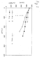
Fig. 1 shows a graph on which the relation of cell
capacity with the number of charge-discharge cycles is plotted.
In the graph, symbols ▵, and ○ show data using No. 1, No. 2
and No. 3 positive electrode active materials, respectively.
It is apparent from the graph that the cell using No.
3 active material smaller in specific surface area and larger
in half-value width than the range of the present invention
exhibits remarkable lowering of capacity with the increase of
the number of cycles whereas the cell using No. 2 active
material according to the present invention exhibits slow
reduction of capacity and, furthermore, the cell using No. 1
active material large in specific surface area and small in
half-value width exhibits a tendency to keep the capacity high.
Example 2
A positive electrode active material used in this
example was lithium-nickel-cobalt complex oxide LiNi0.10Co0.90O2
having a specific surface area of 1.4m2/g, a half-value width
of the (003) plane of 0.20 and a half-value width of the (104)
plane of 0.20. A cell was produced in the same condition as in
Example 1 except the aforementioned condition, and then the
charge-discharge cycle was repeated.
As a result, the 300th-cycle discharge capacity was
400mAh, so that a performance nearly equal to that of the cell
using No. 1 active material LiCoO2 in Example 1 was obtained.
Example 3
A positive electrode active material used in this
example was lithium-cobalt complex oxide LiCoO2 having a
specific surface area of 1.8m2/g, a halt-value width of the
(003) plane of 0.105 and a half-value width of the (104) plane
of 0.120. Further, the proportion of a positive electrode
mixture was set to be 85wt% of LiCoO2, 7wt% of acetylene black
powder and 8wt% of PVDF. A cell was produced in the same
condition as in Example 1 except the aforementioned condition
and then the charge-discharge cycle was repeated.
As a result, the 300th-cycle discharge capacity was
390mAh, so that a performance nearly equal to that of the cell
using No. 1 active material LiCoO2 in Example 1 was obtained.
Comparative Example 1
A positive electrode active material used in this
comparative example was lithium-nickel-cobalt complex oxide
LiNi0.37Co0.63O2 having a specific surface area of 2.2m2/g, a half-value
width of the (003) plane of 0.220 and a half-value width
of the (104) plane of 0.215. A cell was produced in the same
condition as in Example 1 except the aforementioned condition,
and then the charge-discharge cycle was repeated.
As a result, the first-cycle discharge capacity was
410mAh, so that the cell was inferior in performance to any
cell using LiCoO2 in Example 1.
Comparative Example 2
A positive electrode active material used in this
comparative example was lithium-nickel-cobalt complex oxide
LiNi0.37Co0.63O2 having a specific surface area of 0.28m2/g, a
half-value width of the (003) plane of 0.097 and a half-value
width of the (104) plane of 0.100. A cell was produced in the
same condition as in Example 1 except the aforementioned
condition, and then the charge-discharge cycle was repeated.
As a result, from the first-cycle discharge time, the
voltage increased to no more than 2.20V.
Comparative Example 3
A positive electrode active material used in this
comparative example was lithium-nickel-cobalt complex oxide
LiNi0.37Co0.63O2 having a specific-surface area of 2.3m2/g, a half-value
width of the (003) plane of 0.51 and a half-value width
of the (104) plane of 0.52. Though a trial to produce a cell
in the same condition as in Example 1 except the aforementioned
condition was made, not only the positive electrode active
material scattered at the time of preparing paste but also the
positive electrode active material in the paste was aggregated.
As a result, the paste could not be applied to the support
uniformly.
Further, a lithium secondary cell according to the
present invention includes a material capable of
occluding/exuding lithium in a positive electrode and a
material mainly containing graphite in a negative electrode.
In the lithium secondary cell, the quantity of lithium occluded
in the negative electrode in a fully-charged state is smaller
than 55% of the theoretical lithium occlusion capacity of the
negative electrode.
The inventors of the present invention produced samples
by way of trial so that the quantity of lithium occluded in the
negative electrode plate mainly containing graphite was changed
variously, enclosed the samples in small-sized closed packages
of stainless steel, and researched the correlation between the
quantity of lithium occluded and the thermal stability of the
negative electrode plate by using a differential calorimeter
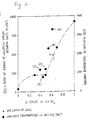
(DSC). As a result, it was found that the calorific value
between 200°C and 350°C increases remarkably when the quantity
of lithium occluded is not smaller than 55% of the theoretical
occlusion capacity as shown in Fig. 2 which will be described
later, that is, when the composition of graphite in the
negative electrode in a fully-charged state exceeds Li0.55C6.
Preferably, according to Fig. 2, the quantity of lithium
occluded is in a range of 30% to 50%.
Then, as will be shown in the following examples, the
inventors produced lithium cells different in the quantity of
lithium occluded in the graphite negative electrode plate in a
fully-charged state variously by way of trial and applied a
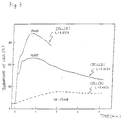
nailing test to the cells. As a result, it was found as shown
in Fig. 3 that the maximum value of the surface temperature of
the cell decreases as the quantity of lithium occluded in the
graphite negative electrode plate decreases. In this occasion,
firing and fuming were observed in the cases of Li0.62C6 and
Li0.55C6 whereas these phenomena did not occur in the case of
Li0.45C6. Furthermore, even the operation of a safety valve
opened with the increase of the internal pressure of the
storage cell did not observed, so that the cell was found to be
very safe. It was found from the previous result of the
differential calorimetry and the result of the nailing test
that the calorific value of the cell decreases remarkably when
the quantity of lithium intercalation to the negative electrode
mainly containing graphite in a fully-charged state is smaller
than 55%, that is, when the composition of the graphite
negative electrode is smaller than Li0.55C6 as shown in Fig. 2.
The inventors of the present invention consider that
the aforementioned phenomenon is caused by the fact that there
is not induced any interaction with large heat such as direct
interaction between graphite and occluded lithium when the
quantity of lithium occluded in the graphite negative electrode
is smaller than 55%, because graphite is thermally stable even
if the large short-circuit current by the nailing test raises
the internal temperature of the cell.
Example 4
Fig. 4A is a plan view showing the lithium secondary
battery according to the present invention; and Fig. 4B is a
partly cutaway sectional view of the cell according to the
present invention. The cell of this example is a rectangular
lithium secondary cell in which rivet type terminals 1 are
caulked to be fixed to a cell case 3 through gaskets 2. The
cell case 3 is designed so that a sealing plate and a case body
are molded by a material obtained by laminating a resin film on
a steel plate and are then airtightly sealed by a double-rolled
sealing method. The reference numeral 4 designates an
explosion valve type safety valve using a metal film. The
reference numeral 5 designates a cell generator element formed
by winding belt-shaped positive and negative electrode plates
ellipsoidally spirally through a separator. The positive and
negative electrode plates of the cell generator element 5 are
electrically connected to the rivet terminals 1, respectively,
in the cell.
The positive electrode plate was produced by: mixing
LiCoO2 as an active material, carbon powder as a conduction
assisting agent and polyvinylidene fluoride as a binding agent;
dissolving the mixture in N-methylpyrolidone as a solvent to
form paste; applying the paste onto an aluminum foil; and
heating, pressing and molding the aluminum foil to which the
paste is applied.
The negative electrode plate was produced by: mixing
artificial graphite with polyvinylidene fluoride as a binding
agent; dissolving the mixture in N-methylpyrolidone as a
solvent to form paste; applying the paste onto a copper foil;
and heating, pressing and molding the copper foil.
As an electrolyte, 1M LiPF6/ethylene carbonate +
dimethyl carbonate + diethyl carbonate DEC (2:2:1) was injected
into the aforementioned cell.
A cell in which the quantity of lithium occluded into
graphite of the negative electrode is set to be smaller than
55% (Li0.55C6) of the theoretical capacity thereof by adjusting
the quantities of active materials in the positive and negative
electrode plates when the cell is fully charged up to 4.1V is
made the cell of the present invention. In this occasion,
three kinds of cells (A), (B) and (C) of the same structure
except that the quantities of lithium occluded into the
respective negative electrodes were set to be in values shown
in Table 2, were produced by way of trial.
For the sake of comparison, cells (D) and (E) which
were the same structure as above except that the quality of
lithium occluded in the negative electrode in a fully-charged
state exceeded 55% of the theoretical occlusion capacity.
| Cell No. | Quantity of Lithium Occluded into Negative Electrode While Fully Discharged | Discharge Capacity (mAh) |
| (A) | Li0.52C6 | 870 |
| (B) | Li0.45C6 | 820 |
| (C) | Li0.40C6 | 760 |
| (D) | Li0.55C6 | 980 |
| (E) | Li0.62C6 | 1040 |
The aforementioned nailing test was applied to these
cells, and the results of Fig. 2 were obtained. That is, it
became clear from the nailing test that, when the quantity of
lithium occluded into graphite contained in the negative
electrode in a fully-charged state is set to be smaller than
55% of the theoretical occlusion capacity, a lithium secondary
cell which is very high in safety so that firing/fuming can be
prevented is obtained.