EP0959360B1 - Méthode de régulation de trame - Google Patents
Méthode de régulation de trame Download PDFInfo
- Publication number
- EP0959360B1 EP0959360B1 EP99300916A EP99300916A EP0959360B1 EP 0959360 B1 EP0959360 B1 EP 0959360B1 EP 99300916 A EP99300916 A EP 99300916A EP 99300916 A EP99300916 A EP 99300916A EP 0959360 B1 EP0959360 B1 EP 0959360B1
- Authority
- EP
- European Patent Office
- Prior art keywords
- rasterization
- data
- address pairs
- controlling
- activity according
- Prior art date
- Legal status (The legal status is an assumption and is not a legal conclusion. Google has not performed a legal analysis and makes no representation as to the accuracy of the status listed.)
- Expired - Lifetime
Links
- 238000000034 method Methods 0.000 title claims description 18
- 230000000694 effects Effects 0.000 claims description 11
- 230000015654 memory Effects 0.000 claims description 8
- 230000006399 behavior Effects 0.000 description 6
- 230000002688 persistence Effects 0.000 description 6
- 239000000872 buffer Substances 0.000 description 2
- 238000013481 data capture Methods 0.000 description 2
- 230000007423 decrease Effects 0.000 description 2
- 238000010586 diagram Methods 0.000 description 2
- 238000012986 modification Methods 0.000 description 2
- 230000004048 modification Effects 0.000 description 2
- 230000003252 repetitive effect Effects 0.000 description 2
- 238000012360 testing method Methods 0.000 description 2
- 238000013459 approach Methods 0.000 description 1
- 238000005282 brightening Methods 0.000 description 1
- 239000002131 composite material Substances 0.000 description 1
- 230000003247 decreasing effect Effects 0.000 description 1
- 230000001934 delay Effects 0.000 description 1
- 238000013461 design Methods 0.000 description 1
- 230000006870 function Effects 0.000 description 1
- 239000011159 matrix material Substances 0.000 description 1
- 238000012545 processing Methods 0.000 description 1
- 238000009738 saturating Methods 0.000 description 1
- 238000001228 spectrum Methods 0.000 description 1
- 230000003068 static effect Effects 0.000 description 1
Images
Classifications
-
- G—PHYSICS
- G01—MEASURING; TESTING
- G01R—MEASURING ELECTRIC VARIABLES; MEASURING MAGNETIC VARIABLES
- G01R13/00—Arrangements for displaying electric variables or waveforms
- G01R13/20—Cathode-ray oscilloscopes
- G01R13/22—Circuits therefor
-
- G—PHYSICS
- G01—MEASURING; TESTING
- G01R—MEASURING ELECTRIC VARIABLES; MEASURING MAGNETIC VARIABLES
- G01R13/00—Arrangements for displaying electric variables or waveforms
- G01R13/20—Cathode-ray oscilloscopes
- G01R13/22—Circuits therefor
- G01R13/34—Circuits for representing a single waveform by sampling, e.g. for very high frequencies
-
- G—PHYSICS
- G09—EDUCATION; CRYPTOGRAPHY; DISPLAY; ADVERTISING; SEALS
- G09G—ARRANGEMENTS OR CIRCUITS FOR CONTROL OF INDICATING DEVICES USING STATIC MEANS TO PRESENT VARIABLE INFORMATION
- G09G1/00—Control arrangements or circuits, of interest only in connection with cathode-ray tube indicators; General aspects or details, e.g. selection emphasis on particular characters, dashed line or dotted line generation; Preprocessing of data
- G09G1/06—Control arrangements or circuits, of interest only in connection with cathode-ray tube indicators; General aspects or details, e.g. selection emphasis on particular characters, dashed line or dotted line generation; Preprocessing of data using single beam tubes, e.g. three-dimensional or perspective representation, rotation or translation of display pattern, hidden lines, shadows
- G09G1/14—Control arrangements or circuits, of interest only in connection with cathode-ray tube indicators; General aspects or details, e.g. selection emphasis on particular characters, dashed line or dotted line generation; Preprocessing of data using single beam tubes, e.g. three-dimensional or perspective representation, rotation or translation of display pattern, hidden lines, shadows the beam tracing a pattern independent of the information to be displayed, this latter determining the parts of the pattern rendered respectively visible and invisible
Definitions
- This invention relates to the rasterization of acquired data-address pairs so as to prepare the data they contain for the raster scan display of a digital oscilloscope, and more particularly to how such oscilloscopes operate in the presence of a low or non-existent trigger rate and the resulting shortage of waveforms for rasterization.
- Modern digital oscilloscopes typically acquire and digitize input data representative of the behavior over time of an electrical signal.
- the resulting data-address pairs are typically "rasterized" to convert them into a two-dimensional bit-map for display by a raster scan display.
- Raster scan displays like those in computer monitors, utilize a two-dimensional matrix of pixels arranged in rows and columns.
- Grey-scale raster scan displays can also provide "variable persistence", a way for the user to control how quickly or slowly the intensity of each illuminated pixel is decreased over time if no new intensity information is directed to that pixel.
- the intensity values stored for the individual pixels at the locations associated with these waveforms are made brighter by some increment value. All illuminated pixels are also decremented on each display cycle. Pixels that are part of the waveform display of a repetitive waveform eventually attain a maximum intensity value and are displayed brightly, while pixels that are part of an intermittent feature of the waveform appear dimmer, depending on how infrequently that intermittent part of the waveform occurs and therefor how often they receive an additional increment of intensity value.
- Infinite persistence refers to the oscilloscope display's behavior when illuminated pixel's intensity is not decremented at all.
- intensity data is only added to pixel values, never subtracted. In this mode, all of the pixels affected by repetitive waveforms eventually reach their maximum intensity values and stay there until the display settings are modified.
- a trigger signal indicates to the oscilloscope that some external event has met preestablished criteria defining when another data acquisition would be appropriate. In its simplest form, a trigger can be generated every time that the signal under test crosses a particular voltage level going in a particular direction.
- the "raw" trigger signal, a.k.a. main event trigger (MET) becomes active every time external events meet the preestablished criteria.
- MET main event trigger
- the oscilloscope may not be ready to make another acquisition yet. Raw triggers are ignored until the oscilloscope itself is again in a state of readiness to do another acquisition.
- a signal indicative of this readiness is typically ANDed with the MET to produce a MAT, or main accepted trigger.
- This is the trigger signal that controls data acquisition, since it means that both the external event and the rest of the oscilloscope are now at a suitable time for referencing the acquisition of another data record.
- the oscilloscope When the MAT occurs, the oscilloscope performs a sequence of activities to capture, or retain, data that is representative of the behavior of the signal under test.
- the trigger event may initiate data capture, or terminate it, or provide a reference point somewhere in the middle of the acquired data record.
- Use of a circular data acquisition memory makes the time relationship between the trigger event and the time of the actual data capture highly adjustable.
- the data acquisition interval and the waveform rasterization period may vary widely with respect to each other, it is generally desirable to try to keep them happening in parallel with each other to maximize throughput. Under some circumstances, however, the rate of the MET, or external trigger, is highly variable. This can cause a variation in signal intensity that is irritating or frustrating to the user.
- the waveform display will tend to go to maximum intensity in every illuminated pixel, thereby "saturating" the display.
- the user may become quite frustrated by the need to constantly adjust the brightness control in an effort to produce a display with satisfactory intensity.
- What is desired is some way to continue to provide a useful display in the presence of a fluctuating trigger rate.
- this problem has been discussed in the context of multi-bit raster scan displays with persistence, an ideal solution should also work for single bit rasterizations too.
- one or more recently acquired waveform data sets are maintained in memory after they are initially rasterized.
- the trigger and waveform acquisition rates become so low that rasterizer time is being wasted, one or more of the most recent previously acquired waveforms are automatically re-rasterized and displayed again to maintain the display until another newly acquired waveform becomes available.
- the rasterizer's readiness to re-rasterize a previously rasterized waveform data set can be qualified with a pre-determined or programmable time delay, thereby providing more flexibility for external circuitry and controllers to optimize utilization of the rasterizer's behavior.
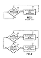
- FIG. 1 is a logic diagram illustrating how rasterization was controlled according to the prior art.
- FIG. 2 is a logic diagram illustrating how rasterization is controlled according to the present invention.
- rasterizer behavior simply waited for new waveforms to become available 10 , and only continued rasterizing 12 after new waveform data became available.
- decision block 10 if a new waveform or the trigger associated with a new waveform is not available after a previous rasterization, decision block 10 produces a "no". This "no" starts the delay interval referred to in decision block 11. So long as the delay interval lasts, the "no" output of decision block 11 keeps sending the logical inquiry back to decision block 10, which is waiting for the arrival of the information that a new trigger signal has been received and a new waveform will soon be available. If no such information is received within the predetermined delay interval 11 , decision block 11 produces a "yes" outcome and the rasterizer then performs a re-rasterization 13 of a previously rasterized waveform data set.
- the delay interval of block 11 is provided by a counter/timer.
- the counter/timer is reset, or initialized to zero, continuously whenever the rasterizer referred to in blocks 12 and 13 is running, or when a trigger associated with the next waveform has been received, i.e., "yes" from decision block 10 .
- the reset or initialization signal is withdrawn and the counter/timer is allowed to count for the time of the delay interval, unless it is interrupted and reset by the availability of another trigger signal and the availability of a new waveform that such a trigger signal implies.
- the "wait time” value can be set to zero, effectively eliminating decision block 11 from the method of the invention. With decision block 11 gone, or its wait time set to zero, rasterization of an old waveform begins immediately upon completion of the previous rasterization if no trigger signal indicates that new waveform data is available.
- the ability to set the wait time is a general purpose control input that allows this re-rasterization technique to be optimized for a variety of operational environments. Since waveform data acquisition time can have various relationships with the time taken by the rasterization process, it may be desirable to lengthen, or shorten, or make equal to zero, the wait time before undertaking a re-rasterization. If new waveforms are being acquired very quickly compared with the time it is taking to rasterize them, the wait time should be set to be long enough to ensure that the rasterizer waits for the arrival of the next new waveform rather than starting with any re-rasterizations.
- the slow display of this design only provided a single bit of intensity data per pixel and therefore had no analog-like gray scaling capability. Nonetheless, the two single bit per pixel raster memories were used in a way that gave the operator some indication of the presence of intermittent signals. This was accomplished by using a randomizing process to qualify the compositing of the most recent waveform into the previously accumulated waveforms. With this approach, waveforms that were sufficiently intermittent only showed up as dotted lines, while waveforms that occurred most of the time would generally appear as completely filled in. Because of the single bit per pixel limitation of this implementation, extremely rare and not-so rare waveforms would tend to be misidentified, respectively, as not discernable or as always present.
- rasterization schemes that include some form of randomization in their output are ideally suited for re-rasterization according to this invention. Rasterization processes that do not include any randomizing function at all will produce static displays when a single waveform is repeatedly re-rasterized. This might be a case where the re-rasterization of more that one waveform would lead to a more natural and active looking display.
Landscapes
- Physics & Mathematics (AREA)
- General Physics & Mathematics (AREA)
- Controls And Circuits For Display Device (AREA)
- Image Generation (AREA)
Claims (9)
- Procédé de régulation de l'activité de rastérisation pour générer des affichages de formes d'ondes dans un instrument d'acquisition de données électroniques, le procédé comprenant les étapes consistant à :(a) acquérir à plusieurs reprises de nouvelles séquences de données représentatives de formes d'ondes de signaux électroniques et à stocker les séquences de données dans une mémoire en tant que séquences de paires d'adresses de données ;(b) rastériser une séquence de paires d'adresses de données provenant de la mémoire pour générer une image d'écran à balayage de trame pour un stockage dans une mémoire de trame ;(c) déterminer si une nouvelle séquence de paires d'adresses de données est disponible ou non, c'est-à-dire prête pour la rastérisation ;(d) si une nouvelle séquence de paires d'adresses de données est prête pour la rastérisation selon la détermination de l'étape (c), la réalisation de l'étape (b) sur la nouvelle séquence de paires d'adresses de données ; et(e) si une nouvelle séquence de paires d'adresses de données n'est pas disponible pour la rastérisation selon la détermination de l'étape (c), la réalisation de l'étape (b) de nouveau sur une séquence de paires d'adresses de données préalablement rastérisées ;
- Procédé de régulation de l'activité de rastérisation selon la revendication 1, dans lequel l'étape (c), l'étape de détermination comprend les étapes consistant à :(c.1) attendre pendant un intervalle de latence pour voir si une nouvelle séquence de paires d'adresses de données devient prête pour la rastérisation ;(c.2) cesser d'attendre et à passer à l'étape (d) si une nouvelle séquence de paires d'adresses de données est ou devient prête pour la rastérisation ; et(c.3) à la fin de l'intervalle de latence d'attente, passer à l'étape (e).
- Procédé de régulation de l'activité de rastérisation selon la revendication 2, dans lequel l'intervalle de latence est présent et constant.
- Procédé de régulation de l'activité de rastérisation selon la revendication 2, dans lequel l'intervalle de latence est variable.
- Procédé de régulation de l'activité de rastérisation selon la revendication 2, dans lequel l'intervalle de latence est variable et sous le contrôle d'autres éléments de l'instrument d'acquisition des données électroniques au cours de l'opération.
- Procédé de régulation de l'activité de rastérisation selon la revendication 1, dans lequel l'étape (e) comprend la réalisation de l'étape (b) plus d'une fois.
- Procédé de régulation de l'activité de rastérisation selon la revendication 1, dans lequel l'étape (b) comprend la réalisation de l'étape (b) sur deux ou plusieurs séquences de paires d'adresses de données préalablement rastérisées.
- Procédé de régulation de l'activité de rastérisation selon la revendication 2, dans lequel l'étape (e) comprend la réalisation de l'étape (b) plus d'une fois.
- Procédé de régulation de l'activité de rastérisation selon la revendication 2, dans lequel l'étape (e) comprend la réalisation de l'étape (b) sur deux ou plusieurs séquences de paires d'adresses de données préalablement rastérisées.
Applications Claiming Priority (2)
| Application Number | Priority Date | Filing Date | Title |
|---|---|---|---|
| US09/026,186 US5995117A (en) | 1998-02-19 | 1998-02-19 | Rasterization control method |
| US26186 | 1998-02-19 |
Publications (3)
| Publication Number | Publication Date |
|---|---|
| EP0959360A2 EP0959360A2 (fr) | 1999-11-24 |
| EP0959360A3 EP0959360A3 (fr) | 2000-02-23 |
| EP0959360B1 true EP0959360B1 (fr) | 2003-08-20 |
Family
ID=21830369
Family Applications (1)
| Application Number | Title | Priority Date | Filing Date |
|---|---|---|---|
| EP99300916A Expired - Lifetime EP0959360B1 (fr) | 1998-02-19 | 1999-02-09 | Méthode de régulation de trame |
Country Status (7)
| Country | Link |
|---|---|
| US (1) | US5995117A (fr) |
| EP (1) | EP0959360B1 (fr) |
| JP (1) | JP3263783B2 (fr) |
| KR (1) | KR100552409B1 (fr) |
| CN (1) | CN1145032C (fr) |
| DE (1) | DE69910489T2 (fr) |
| TW (1) | TW417018B (fr) |
Families Citing this family (9)
| Publication number | Priority date | Publication date | Assignee | Title |
|---|---|---|---|---|
| US6104374A (en) * | 1998-02-19 | 2000-08-15 | Tektronix, Inc. | Sparse vector rasterization |
| US6195080B1 (en) * | 1998-04-03 | 2001-02-27 | Tektronix, Inc. | High probability capture of slow trigger rate acquisitions in a digital oscilloscope with variable intensity rasterization |
| US6188384B1 (en) * | 1998-06-05 | 2001-02-13 | Tektronix, Inc. | Reacting to unusual waveforms |
| US6473701B1 (en) * | 1999-11-22 | 2002-10-29 | Tektronix, Inc. | Alternate triggering in digital oscilloscopes |
| US8102396B2 (en) * | 2006-07-17 | 2012-01-24 | Tektronix, Inc. | Apparatus and method for improved measurement speed in test and measurement instruments |
| US8046183B2 (en) * | 2008-03-04 | 2011-10-25 | Tektronix, Inc. | Pre-trigger and post-trigger acquisition for no dead time acquisition system |
| US8330758B2 (en) * | 2008-05-08 | 2012-12-11 | Teledyne Lecroy, Inc. | Statistically-based display processing |
| CN102109540B (zh) * | 2009-12-25 | 2015-05-20 | 北京普源精电科技有限公司 | 一种可以在光栅显示器中显示等效采样波形的数字示波器及其等效采样点的设置方法 |
| CN112578490A (zh) * | 2019-09-30 | 2021-03-30 | 南开大学 | 一种3d打印的低折射率大角度偏折稀疏光栅 |
Family Cites Families (9)
| Publication number | Priority date | Publication date | Assignee | Title |
|---|---|---|---|---|
| US4816813A (en) * | 1986-09-19 | 1989-03-28 | Nicolet Instrument Corporation | Raster scan emulation of conventional analog CRT displays |
| US5602564A (en) * | 1991-11-14 | 1997-02-11 | Hitachi, Ltd. | Graphic data processing system |
| US5412579A (en) * | 1993-04-05 | 1995-05-02 | Tektronix, Inc. | Slow display method for digital oscilloscope with fast acquisition system |
| KR950012931A (ko) * | 1993-10-27 | 1995-05-17 | 김광호 | 레이저 다이오드 및 그의 제조방법 |
| TW276317B (fr) * | 1993-12-17 | 1996-05-21 | Hitachi Seisakusyo Kk | |
| US5530454A (en) * | 1994-04-13 | 1996-06-25 | Tektronix, Inc. | Digital oscilloscope architecture for signal monitoring with enhanced duty cycle |
| JP3139671B2 (ja) * | 1995-04-04 | 2001-03-05 | 横河電機株式会社 | 波形観測装置 |
| JP3753263B2 (ja) * | 1995-08-23 | 2006-03-08 | ヒューレット・パッカード・カンパニー | 画像を処理する方法 |
| US5838973A (en) * | 1996-05-03 | 1998-11-17 | Andersen Consulting Llp | System and method for interactively transforming a system or process into a visual representation |
-
1998
- 1998-02-19 US US09/026,186 patent/US5995117A/en not_active Expired - Lifetime
-
1999
- 1999-02-09 DE DE69910489T patent/DE69910489T2/de not_active Expired - Lifetime
- 1999-02-09 EP EP99300916A patent/EP0959360B1/fr not_active Expired - Lifetime
- 1999-02-10 JP JP03324699A patent/JP3263783B2/ja not_active Expired - Fee Related
- 1999-02-12 TW TW088102349A patent/TW417018B/zh not_active IP Right Cessation
- 1999-02-15 CN CNB991023439A patent/CN1145032C/zh not_active Expired - Fee Related
- 1999-02-19 KR KR1019990005523A patent/KR100552409B1/ko not_active Expired - Fee Related
Also Published As
| Publication number | Publication date |
|---|---|
| DE69910489T2 (de) | 2004-06-24 |
| JPH11281676A (ja) | 1999-10-15 |
| US5995117A (en) | 1999-11-30 |
| CN1236104A (zh) | 1999-11-24 |
| EP0959360A2 (fr) | 1999-11-24 |
| KR100552409B1 (ko) | 2006-02-16 |
| JP3263783B2 (ja) | 2002-03-11 |
| KR19990072768A (ko) | 1999-09-27 |
| TW417018B (en) | 2001-01-01 |
| DE69910489D1 (de) | 2003-09-25 |
| CN1145032C (zh) | 2004-04-07 |
| EP0959360A3 (fr) | 2000-02-23 |
Similar Documents
| Publication | Publication Date | Title |
|---|---|---|
| EP1074845B1 (fr) | Architecture d'oscilloscope numérique pour le contrôle de signaux avec cycle opératoire amélioré | |
| US6104374A (en) | Sparse vector rasterization | |
| EP0959360B1 (fr) | Méthode de régulation de trame | |
| EP0489594B1 (fr) | Système graphique à calculateur | |
| JP2627691B2 (ja) | 表示装置 | |
| KR100720013B1 (ko) | 래스터 디스플레이 디지털 오실로스코프에서 래스터 메모리의 내용에 잔상 감쇠를 제공하는 방법 | |
| US5438655A (en) | Methods and apparatus for updating and antialiasing waveforms | |
| JPH0623794B2 (ja) | 波形表示装置 | |
| US5412579A (en) | Slow display method for digital oscilloscope with fast acquisition system | |
| EP0497494A1 (fr) | Dispositif de cadrage d'image pour un système multimédia | |
| KR19980024576A (ko) | 다수 동시 디스플레이 시스템에서 디지털 디스플레이를 고속 클럭킹하는 시스템 및 방법 | |
| EP0393824A2 (fr) | Curseurs de position pour un générateur de signal de test | |
| US6384825B2 (en) | Method of controlling a sparse vector rasterizer | |
| US5185874A (en) | Address generator for high speed data averager | |
| JP2727036B2 (ja) | バッファ・メモリを用いたトリガ発生方法 | |
| EP0123082A1 (fr) | Appareil d'affichage pour diagrammes logiques des temps | |
| US6201527B1 (en) | Technique for displaying enveloped waveform | |
| US5754439A (en) | Method for reducing display locking in digital oscilloscopes or logic analyzers using inter-acquisition dithering techniques | |
| EP0919818B1 (fr) | Procédé et appareil pour la présentation des formes d'ondes | |
| JPH06317611A (ja) | ビデオ・ライン選択表示装置 | |
| JPH06242146A (ja) | デジタルオシロスコープ | |
| JPH04288594A (ja) | 表示メモリ制御装置 |
Legal Events
| Date | Code | Title | Description |
|---|---|---|---|
| PUAI | Public reference made under article 153(3) epc to a published international application that has entered the european phase |
Free format text: ORIGINAL CODE: 0009012 |
|
| AK | Designated contracting states |
Kind code of ref document: A2 Designated state(s): DE FR GB |
|
| AX | Request for extension of the european patent |
Free format text: AL;LT;LV;MK;RO;SI |
|
| PUAL | Search report despatched |
Free format text: ORIGINAL CODE: 0009013 |
|
| AK | Designated contracting states |
Kind code of ref document: A3 Designated state(s): AT BE CH CY DE DK ES FI FR GB GR IE IT LI LU MC NL PT SE |
|
| AX | Request for extension of the european patent |
Free format text: AL;LT;LV;MK;RO;SI |
|
| RIC1 | Information provided on ipc code assigned before grant |
Free format text: 7G 01R 13/02 A |
|
| 17P | Request for examination filed |
Effective date: 20000706 |
|
| AKX | Designation fees paid |
Free format text: DE FR GB |
|
| GRAH | Despatch of communication of intention to grant a patent |
Free format text: ORIGINAL CODE: EPIDOS IGRA |
|
| GRAS | Grant fee paid |
Free format text: ORIGINAL CODE: EPIDOSNIGR3 |
|
| GRAA | (expected) grant |
Free format text: ORIGINAL CODE: 0009210 |
|
| AK | Designated contracting states |
Designated state(s): DE FR GB |
|
| REG | Reference to a national code |
Ref country code: GB Ref legal event code: FG4D |
|
| REF | Corresponds to: |
Ref document number: 69910489 Country of ref document: DE Date of ref document: 20030925 Kind code of ref document: P |
|
| ET | Fr: translation filed | ||
| PLBE | No opposition filed within time limit |
Free format text: ORIGINAL CODE: 0009261 |
|
| STAA | Information on the status of an ep patent application or granted ep patent |
Free format text: STATUS: NO OPPOSITION FILED WITHIN TIME LIMIT |
|
| 26N | No opposition filed |
Effective date: 20040524 |
|
| REG | Reference to a national code |
Ref country code: FR Ref legal event code: PLFP Year of fee payment: 17 |
|
| PGFP | Annual fee paid to national office [announced via postgrant information from national office to epo] |
Ref country code: DE Payment date: 20150226 Year of fee payment: 17 |
|
| PGFP | Annual fee paid to national office [announced via postgrant information from national office to epo] |
Ref country code: FR Payment date: 20150217 Year of fee payment: 17 Ref country code: GB Payment date: 20150226 Year of fee payment: 17 |
|
| REG | Reference to a national code |
Ref country code: DE Ref legal event code: R119 Ref document number: 69910489 Country of ref document: DE |
|
| GBPC | Gb: european patent ceased through non-payment of renewal fee |
Effective date: 20160209 |
|
| REG | Reference to a national code |
Ref country code: FR Ref legal event code: ST Effective date: 20161028 |
|
| PG25 | Lapsed in a contracting state [announced via postgrant information from national office to epo] |
Ref country code: FR Free format text: LAPSE BECAUSE OF NON-PAYMENT OF DUE FEES Effective date: 20160229 Ref country code: DE Free format text: LAPSE BECAUSE OF NON-PAYMENT OF DUE FEES Effective date: 20160901 Ref country code: GB Free format text: LAPSE BECAUSE OF NON-PAYMENT OF DUE FEES Effective date: 20160209 |