EP0959348B1 - Sensor element and gas sensor - Google Patents
Sensor element and gas sensor Download PDFInfo
- Publication number
- EP0959348B1 EP0959348B1 EP99303876.9A EP99303876A EP0959348B1 EP 0959348 B1 EP0959348 B1 EP 0959348B1 EP 99303876 A EP99303876 A EP 99303876A EP 0959348 B1 EP0959348 B1 EP 0959348B1
- Authority
- EP
- European Patent Office
- Prior art keywords
- sensor
- oxygen
- negative electrode
- current
- positive electrode
- Prior art date
- Legal status (The legal status is an assumption and is not a legal conclusion. Google has not performed a legal analysis and makes no representation as to the accuracy of the status listed.)
- Expired - Lifetime
Links
- 229910052760 oxygen Inorganic materials 0.000 claims description 96
- 239000001301 oxygen Substances 0.000 claims description 96
- QVGXLLKOCUKJST-UHFFFAOYSA-N atomic oxygen Chemical compound [O] QVGXLLKOCUKJST-UHFFFAOYSA-N 0.000 claims description 84
- 239000007789 gas Substances 0.000 claims description 62
- 238000005259 measurement Methods 0.000 claims description 56
- 239000007784 solid electrolyte Substances 0.000 claims description 51
- BASFCYQUMIYNBI-UHFFFAOYSA-N platinum Chemical compound [Pt] BASFCYQUMIYNBI-UHFFFAOYSA-N 0.000 claims description 44
- 239000000758 substrate Substances 0.000 claims description 34
- 238000009792 diffusion process Methods 0.000 claims description 33
- 229910052697 platinum Inorganic materials 0.000 claims description 21
- 108010083687 Ion Pumps Proteins 0.000 claims description 18
- 239000000919 ceramic Substances 0.000 claims description 16
- MCMNRKCIXSYSNV-UHFFFAOYSA-N Zirconium dioxide Chemical compound O=[Zr]=O MCMNRKCIXSYSNV-UHFFFAOYSA-N 0.000 claims description 8
- MWUXSHHQAYIFBG-UHFFFAOYSA-N Nitric oxide Chemical compound O=[N] MWUXSHHQAYIFBG-UHFFFAOYSA-N 0.000 description 63
- PNEYBMLMFCGWSK-UHFFFAOYSA-N aluminium oxide Inorganic materials [O-2].[O-2].[O-2].[Al+3].[Al+3] PNEYBMLMFCGWSK-UHFFFAOYSA-N 0.000 description 14
- -1 CH4) c2H6 Chemical compound 0.000 description 13
- 238000012360 testing method Methods 0.000 description 12
- 238000010304 firing Methods 0.000 description 6
- 238000000034 method Methods 0.000 description 6
- CURLTUGMZLYLDI-UHFFFAOYSA-N Carbon dioxide Chemical compound O=C=O CURLTUGMZLYLDI-UHFFFAOYSA-N 0.000 description 5
- 238000005086 pumping Methods 0.000 description 5
- 229910002092 carbon dioxide Inorganic materials 0.000 description 4
- 239000001569 carbon dioxide Substances 0.000 description 4
- 230000003247 decreasing effect Effects 0.000 description 4
- 150000002500 ions Chemical class 0.000 description 4
- UGFAIRIUMAVXCW-UHFFFAOYSA-N Carbon monoxide Chemical compound [O+]#[C-] UGFAIRIUMAVXCW-UHFFFAOYSA-N 0.000 description 3
- 229910001260 Pt alloy Inorganic materials 0.000 description 3
- 229910002091 carbon monoxide Inorganic materials 0.000 description 3
- 238000006243 chemical reaction Methods 0.000 description 3
- 230000007423 decrease Effects 0.000 description 3
- TXKMVPPZCYKFAC-UHFFFAOYSA-N disulfur monoxide Inorganic materials O=S=S TXKMVPPZCYKFAC-UHFFFAOYSA-N 0.000 description 3
- 238000009413 insulation Methods 0.000 description 3
- XTQHKBHJIVJGKJ-UHFFFAOYSA-N sulfur monoxide Chemical compound S=O XTQHKBHJIVJGKJ-UHFFFAOYSA-N 0.000 description 3
- 230000005540 biological transmission Effects 0.000 description 2
- 238000001514 detection method Methods 0.000 description 2
- 238000010494 dissociation reaction Methods 0.000 description 2
- 230000005593 dissociations Effects 0.000 description 2
- 239000003792 electrolyte Substances 0.000 description 2
- 238000002474 experimental method Methods 0.000 description 2
- 238000010438 heat treatment Methods 0.000 description 2
- 230000001771 impaired effect Effects 0.000 description 2
- 239000000463 material Substances 0.000 description 2
- 238000007639 printing Methods 0.000 description 2
- 239000006104 solid solution Substances 0.000 description 2
- ODINCKMPIJJUCX-UHFFFAOYSA-N Calcium oxide Chemical compound [Ca]=O ODINCKMPIJJUCX-UHFFFAOYSA-N 0.000 description 1
- 239000004215 Carbon black (E152) Substances 0.000 description 1
- 229910000629 Rh alloy Inorganic materials 0.000 description 1
- 230000004913 activation Effects 0.000 description 1
- 229910045601 alloy Inorganic materials 0.000 description 1
- 239000000956 alloy Substances 0.000 description 1
- 239000000292 calcium oxide Substances 0.000 description 1
- 235000012255 calcium oxide Nutrition 0.000 description 1
- 230000003197 catalytic effect Effects 0.000 description 1
- 238000004891 communication Methods 0.000 description 1
- 239000002131 composite material Substances 0.000 description 1
- 230000006735 deficit Effects 0.000 description 1
- 239000011521 glass Substances 0.000 description 1
- 229930195733 hydrocarbon Natural products 0.000 description 1
- 150000002430 hydrocarbons Chemical class 0.000 description 1
- 239000000203 mixture Substances 0.000 description 1
- SIWVEOZUMHYXCS-UHFFFAOYSA-N oxo(oxoyttriooxy)yttrium Chemical compound O=[Y]O[Y]=O SIWVEOZUMHYXCS-UHFFFAOYSA-N 0.000 description 1
- RVTZCBVAJQQJTK-UHFFFAOYSA-N oxygen(2-);zirconium(4+) Chemical compound [O-2].[O-2].[Zr+4] RVTZCBVAJQQJTK-UHFFFAOYSA-N 0.000 description 1
- 239000000843 powder Substances 0.000 description 1
- 229910052703 rhodium Inorganic materials 0.000 description 1
- 239000010948 rhodium Substances 0.000 description 1
- MHOVAHRLVXNVSD-UHFFFAOYSA-N rhodium atom Chemical compound [Rh] MHOVAHRLVXNVSD-UHFFFAOYSA-N 0.000 description 1
- 238000007650 screen-printing Methods 0.000 description 1
- 239000005394 sealing glass Substances 0.000 description 1
- 238000005245 sintering Methods 0.000 description 1
- 239000010409 thin film Substances 0.000 description 1
- XLYOFNOQVPJJNP-UHFFFAOYSA-N water Substances O XLYOFNOQVPJJNP-UHFFFAOYSA-N 0.000 description 1
- RUDFQVOCFDJEEF-UHFFFAOYSA-N yttrium(III) oxide Inorganic materials [O-2].[O-2].[O-2].[Y+3].[Y+3] RUDFQVOCFDJEEF-UHFFFAOYSA-N 0.000 description 1
- 229910001928 zirconium oxide Inorganic materials 0.000 description 1
Images


Classifications
-
- G—PHYSICS
- G01—MEASURING; TESTING
- G01N—INVESTIGATING OR ANALYSING MATERIALS BY DETERMINING THEIR CHEMICAL OR PHYSICAL PROPERTIES
- G01N27/00—Investigating or analysing materials by the use of electric, electrochemical, or magnetic means
- G01N27/26—Investigating or analysing materials by the use of electric, electrochemical, or magnetic means by investigating electrochemical variables; by using electrolysis or electrophoresis
- G01N27/403—Cells and electrode assemblies
- G01N27/406—Cells and probes with solid electrolytes
- G01N27/407—Cells and probes with solid electrolytes for investigating or analysing gases
- G01N27/4075—Composition or fabrication of the electrodes and coatings thereon, e.g. catalysts
-
- G—PHYSICS
- G01—MEASURING; TESTING
- G01N—INVESTIGATING OR ANALYSING MATERIALS BY DETERMINING THEIR CHEMICAL OR PHYSICAL PROPERTIES
- G01N27/00—Investigating or analysing materials by the use of electric, electrochemical, or magnetic means
- G01N27/26—Investigating or analysing materials by the use of electric, electrochemical, or magnetic means by investigating electrochemical variables; by using electrolysis or electrophoresis
- G01N27/403—Cells and electrode assemblies
- G01N27/406—Cells and probes with solid electrolytes
- G01N27/407—Cells and probes with solid electrolytes for investigating or analysing gases
- G01N27/4071—Cells and probes with solid electrolytes for investigating or analysing gases using sensor elements of laminated structure
Definitions
- the present invention relates to a gas sensor for sensing gas, such as oxygen (O 2 ), carbon dioxide (CO 2 ), carbon monoxide (CO), water (H 2 O), hydrocarbon (e.g. CH 4 ) c 2 H 6 , or C 3 H 8 ), nitrogen oxide (NOx), or sulfur oxide (SOx), and more particularly to a flat limiting-current-type sensor and an oxygen-containing gas component sensor in which negative and positive electrodes are disposed on the same side of a solid electrolyte substrate, and the concentration of a particular gas contained in a gas to be measured (hereinafter referred to as "measurement gas”) is determined through restriction of gas diffusion to the negative electrode.
- gas such as oxygen (O 2 ), carbon dioxide (CO 2 ), carbon monoxide (CO), water (H 2 O), hydrocarbon (e.g. CH 4 ) c 2 H 6 , or C 3 H 8 ), nitrogen oxide (NOx), or sulfur oxide (SOx)
- FIG. 12(A) shows a sectional view of an oxygen sensor for determining the oxygen concentration of a measurement gas.
- a pair of electrodes 132 and 134 formed from, for example, porous platinum and having the form of a thick or thin film are formed on opposite sides of an oxygen-ion conductive solid electrolyte substrate 122.
- a voltage is applied between the electrodes 132 and 134 and a resultant current is measured in order to determine an oxygen concentration.
- WO 95/14226 DE 39 38 056 and EP 0 791 828 each disclose gas sensors in which electrodes for measuring the gas are provided on opposite sides of a solid electrolyte substrate.
- a housing 124 having a small oxygen diffusion hole 234C formed therein covers the negative electrode 134 so as to limit diffusion of oxygen through the oxygen diffusion hole 234C, so that a value of current proportional to oxygen concentration is obtained.
- Such an oxygen sensor must be provided with a heater for heating a solid electrolyte substrate to a temperature of 500°C to 900°C in order to activate the solid electrolyte substrate.
- a heater for heating a solid electrolyte substrate to a temperature of 500°C to 900°C in oder to activate the solid electrolyte substrate.
- the opposite sides of the solid electrolyte substrate bear respective electrodes, attachment of the heater to the oxygen sensor is difficult.
- a flat limiting-current-type sensor as shown in FIG. 12(B) is used.
- a negative electrode 134 and a positive electrode 132 are disposed on the same side of the solid electrolyte substrate 122. Since the electrodes 132 and 134 are disposed on the same side of the solid electrolyte substrate 122, the flat limiting-current-type sensor has an advantage in that a heater can be readily disposed on the other side of the solid electrolyte substrate 122.
- the configuration of the flat limiting-current-type sensor is described in detail in Japanese Patent Application Laid-open ( kokai ) No. 2-147853 filed by the present applicants. This document is considered to represent the closest prior art, and forms the basis of the precharacterizing portion of claim 1.
- FIG. 12(C) shows the flat limiting-current-type sensor of FIG. 12(B) as viewed in the direction of arrow C of FIG. 12(B), i.e., FIG. 12(C) shows a side view of the flat limiting-current-type sensor. Since the negative electrode 134 and the positive electrode 132 are disposed on the same side of the solid electrolyte substrate 122, the area of the negative electrode 134 (positive electrode 132) is subsequently half that in the case of the limiting-current-type sensor of FIG. 12(A) . Accordingly, the flat limiting-current-type sensor of FIG. 12(B) has a problem in that an element resistance becomes higher and that measurement accuracy becomes poorer, as compared to the sensor of FIG. 12(A) .
- an object of the present invention is to provide a flat limiting-current-type sensor having an improved measurement accuracy for a given device size.
- the present inventors realized that, in a sensor element, a negative electrode and a positive electrode might not operate in a similar manner.
- the flat limiting-current-type sensor repeats an oxygen-related pumping cycle. Specifically, oxygen is pumped into a solid electrolyte substrate in the form of ions at the interface between the solid electrolyte substrate and the porous negative electrode. The pumped-in oxygen ions are transmitted through the solid electrolyte substrate. Then, the transmitted oxygen ions are pumped out in the form of oxygen at the interface between the solid electrolyte substrate and the porous positive electrode.
- the present inventors assumed that there might be a difference between the readiness of reaction for pumping in oxygen in the form of ions and the readiness of reaction for pumping out oxygen ions in the form of oxygen.
- the area of the negative electrode is equal to that of the positive electrode; consequently, transmission of ions is controlled by the negative electrode or the positive electrode, whichever is lower in terms of readiness for reaction, with a resultant increase in element resistance.
- the inventors conducted experiment on the basis of the assumption and obtained an appropriate area ratio between the negative electrode and the positive electrode.
- the present invention provides a sensor element comprising negative and positive electrodes disposed on the same side of a solid electrolyte substrate, and a circuit for applying an electric potential between said negative electrode and said positive electrode so as to determine a gas concentration, characterized in that: the area of said negative electrode and the area of said positive electrode differ by at least twofold.
- this can be used to lower the element resistance of the flat limiting-current-type sensor, thus improving measurement accuracy or S/N ratio.
- the ratio between the area of the negative electrode and the area of the positive electrode is set within a range of 2:1 to 5:1, thereby enabling the element resistance to be reduced to 94% to 86% of that in the case where the negative electrode and the positive electrode assume the same area.
- the measurement accuracy of a flat limiting-current-type sensor can be improved.
- the ratio between the area of the negative electrode and the area of the positive electrode is set within a range of 1:2 to 1:5, thereby enabling the element resistance to be reduced to 74% to 73 % of that in the case where the negative electrode and the positive electrode assume the same area.
- the measurement accuracy of a flat limiting-current-type sensor can be improved.
- the ratio between the area of the negative electrode and the area of the positive electrode is set within a range of 1:2 to 1:5, thereby enabling the element resistance to be reduced to 90% to 82% of that in the case where the negative electrode and the positive electrode assume the same area.
- the measurement accuracy of a flat limiting-current-type sensor can be improved.
- the ratio between the area of the negative electrode and the area of the positive electrode is set within a range of 2:1 to 5:1, thereby enabling the element resistance to be reduced to 81% to 63% of that in the case where the negative electrode and the positive electrode assume the same area.
- the measurement accuracy of a flat limiting-current-type sensor can be improved.
- FIG. 1 shows a flat limiting-current-type sensor 10 of the first embodiment serving as an oxygen sensor.
- FIG. 2(A) is a sectional view of the flat limiting-current-type sensor of FIG. 1 taken along line A-A of FIG. 1 .
- FIG. 2(B) is a side view of the flat limiting-current-type sensor of FIG. 1 as viewed in the direction of arrow D of FIG. 1 (as viewed from the front side).
- the flat limiting-current-type sensor 10 includes a sensor element 20 for measuring oxygen concentration and a ceramic heater 40 for heating the sensor element to a temperature of 500°C to 600°C. The sensor element 20 and the ceramic heater 40 are bonded together by means of glass.
- the flat limiting-current-type sensor 10 measures 0.3 mm (thickness) x 5 mm (width) x 23 mm (height).
- the sensor element 20 includes solid electrolyte substrates 22 and 24 formed from zirconia, which exhibits good conductance of oxygen ions; a positive electrode 32a formed from porous platinum; a lead portion 32b (see FIG.
- connection electrode 34f for supplying current to the positive electrode 32a; a connection electrode 34f connected to a platinum wire 36; a negative electrode 34a formed from porous platinum; a lead portion 34b for supplying current to the negative electrode 34a; a connection electrode 32f connected to a platinum wire 38; a gas diffusion portion 34c extending sideward from the lead portion and adapted to introduce an ambient gas into the negative electrode 34a; and a gas outlet hole 26 for releasing oxygen from the positive electrode 32a to the exterior of the sensor element 20.
- the negative electrode 34a and the positive electrode 32a assume a thickness of about 20 ⁇ m.
- the gas diffusion portion 34c formed from porous platinum extends from the lead portion 34b to the periphery of the sensor element 20 so as to supply oxygen to the negative electrode 34a under a diffusion resistance.
- the gas diffusion portion 34c may assume the form of a small hole for supplying oxygen to the negative electrode 34a.
- FIG. 3 is a side view of the flat limiting-current-type sensor of FIG. 1 as viewed in the direction of arrow B of FIG. 1 (as viewed from the back side).
- the ceramic heater 40 is partially broken.
- the ceramic heater 40 includes an alumina substrate 42 and an alumina substrate 44, both of which have an external size identical to that of the sensor element 20.
- the ceramic heater 40 further includes a heater electrode (heat-generating portion) 46a having a narrow width and assuming a substantially M-shaped form; heater electrodes (lead portions) 46b and 46c having a wide width; and heater connection electrodes 46d and 46e connected to platinum wires 56 and 58, respectively.
- the heater electrode 46a When current flows to the thin heater electrode (heat-generating portion) 46a via the platinum wires 56 and 58, the heater electrode 46a generates heat to thereby heat to a temperature of about 550°C a tip portion of the sensor element 20 where the negative electrode 34a and the positive electrode 32a, which have been described with reference to FIG. 1 ,, are disposed.
- the flat limiting-current-type sensor 10 is placed in an atmosphere of a certain oxygen concentration.
- Current is supplied to the ceramic heater 40 so as to heat the sensor element 20 (solid electrolyte substrate 22) to an ion conduction temperature (activation temperature: about 500°C to 600°C).
- activation temperature about 500°C to 600°C.
- the thus-transmitted oxygen ions are caused to discharge at the interface between the solid electrolyte substrate 22 and the positive electrode 32a, thereby returning to oxygen molecules.
- the thus-formed oxygen is discharged through the gas outlet hole 26. In other words, oxygen is pumped between the negative electrode 34a and the positive electrode 32a, so that current flows through the sensor element 20.
- the amount of oxygen introduced via the gas diffusion portion 34c of porous platinum is limited to a predetermined value (IL1). Specifically, since the amount of oxygen introduced via the gas diffusion portion 34c is limited, even when the voltage applied to the sensor element 20 is increased from V1 to V2, current flowing through the sensor element 20 is maintained at a constant value of IL1.
- Curve b corresponds to the case of low oxygen concentration in an atmosphere to be measured. In the case of low oxygen concentration, current flowing through the sensor element 20 assumes a constant value of IL2 lower than IL1.
- Current c corresponds to the case where an atmosphere to be measured has oxygen concentration higher than that in the case of curve a. In the case of high oxygen concentration, current flowing through the sensor element 20 assumes a constant value of IL3 higher than IL1. On the basis of the differential between these constant values of current, oxygen concentration is determined.
- curves a', b', and c' show voltage-current characteristics of a flat limiting-current-type sensor which has a high V/I value, i.e., a high element resistance and in which the amount of diffusion of oxygen is decreased at the gas introduction portion.
- Curve a' is obtained through measurement conducted at oxygen concentration identical to that as employed in the case of curve a.
- Curve b' is obtained through measurement conducted at oxygen concentration (low concentration) identical to that as employed in the case of curve b.
- Curve c' is obtained through measurement conducted at oxygen concentration (high concentration) identical to that as employed in the case of curve c. As seen from FIG.
- the differential between constant values of current IL1', IL2', and IL3' as observed with the flat limiting-current-type sensor of a high element resistance is smaller than the differential between constant values of current IL1, IL2, and IL3 as observed with the aforementioned flat limiting-current-type sensor of a low element resistance. This indicates that an increase in element resistance causes an impairment in measurement accuracy.
- the area ratio between the negative electrode 34a and the positive electrode 32a is set to 2:1.
- element resistance is reduced, as will be described later, to 74 % that of the conventional flat limiting-current-type sensor which has been described above with reference to FIGS. 12(B) and 12(C) and in which the negative electrode 132 and the positive electrode 134 assume the same area.
- measurement accuracy is improved accordingly.
- a voltage of 0.7 V is applied between the negative electrode 34a and the positive electrode 32a.
- the area ratio between the negative electrode 34a and the positive electrode 32a is set to 2:1, thereby reducing element resistance.
- Element resistance was experimentally measured with respect to different area ratios between the negative electrode 34a and the positive electrode 32a. The test results will be described with reference to FIGS. 5(A) and 6 .
- test samples used the flat limiting-current-type sensor 10 of the first embodiment, which has been described above with reference to FIGS. 1 to 3 . Specifically, while the sum of the areas of the negative and positive electrodes 34a and 32a, respectively, was held constant, the area of the negative electrode 34a and the area of the positive electrode 32a were varied for measurement of element resistance. Test samples assumed the following area ratios of (area of negative electrode 34a):(area of positive electrode 32a): 6:1; 5:1; 4:1; 3:1; 2:1 (flat limiting-current-type sensor of first embodiment) ; 1:1 (conventional flat limiting-current-type sensor shown in FIG.
- test samples were heated to a sensor element temperature of 600°C by means of a heater.
- the test samples were placed in a thermostat-hygrostat chamber maintained at 60°C and 60%RH.
- a voltage of 0.7 V and 1.8 V was applied between the negative electrode 34a and the positive electrode 32a with respect to each of the test samples.
- current flowing through each of the test samples was measured. Element resistance was calculated from the measured current value.
- a voltage of 0.7 V was selected to represent an electric potential which ranges from 0.2 V to 0.8 V and which is applied to a flat limiting-current-type sensor serving as an oxygen sensor.
- a voltage of 0.7 V is considered as a representative for an electric potential ranging from 0.2 V to 1.1 V.
- a voltage of 1.8 V was selected to represent an electric potential which ranges from 1.1 V to 2.5 V and which is applied to a flat limiting-current-type sensor serving as a humidity sensor.
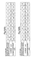
- FIG. 5(A) shows current values as measured when a voltage of 0.7 V is applied to the above test samples and element resistance values calculated from the measured current values.
- FIG. 6 is a graph depicting the measurements of FIG. 5(A) .
- element resistance assumes a value of 8.18 k ⁇ to 7.52 k ⁇ , which is 94% to 86% that in the case where the negative electrode and the positive electrode assume the same area (1:1; element resistance 8.70 k ⁇ ).
- element resistance assumes a value of 6.40 k ⁇ to 6.31 k ⁇ , which is 74 % to 73% that (8.70 k ⁇ ) in the case where the negative electrode and the positive electrode assume the same area.
- the flat limiting-current-type sensor when used as an oxygen sensor, i.e., when a voltage of 0.7 V is applied thereto, through employment of a ratio of 1:2 to 1:5 between the area of the negative electrode and the area of the positive electrode, element resistance can be significantly reduced. Particularly, at a ratio of 1:3 to 1:4, element resistance assumes a minimum value of 5.83 k ⁇ to 5.38 k ⁇ .
- element resistance would be reduced by making the area of the negative electrode 34a greater or smaller than that of the positive electrode 32a.
- element resistance can be reduced in either case of making the area of the negative electrode 34a greater or smaller than that of the positive electrode 32a.
- pumping of oxygen between the positive electrode 32a and the negative electrode 34a is controlled by a plurality of parameters, not by a single parameter.
- element resistance can be reduced by making the size of the negative electrode 34a differ from that of the positive electrode 32a.
- the flat limiting-current-type sensor is used as e.g. an oxygen sensor, wherein a relatively low voltage of about 0.7 V is applied thereto, element resistance can be significantly reduced by making the size of the positive electrode 32a greater than that of the negative electrode 34a.
- FIG. 5(B) shows current values as measured when a voltage of 1.8 V is applied to the above test samples and element resistance values calculated from the measured current values.
- FIG. 7 is a graph depicting the measurements of FIG. 5(B) .
- a humidity sensor wherein a voltage of 1.8 V is applied thereto, through employment of a ratio of 2:1 to 5:1 between the area of the negative electrode and the area of the positive electrode, element resistance can be significantly reduced.
- element resistance assumes a minimum value of 3.90 k ⁇ to 3.86 k ⁇ .
- a characteristic as observed when a voltage of 1.8 V is applied is reverse to that as observed when a voltage of 0.7 V is applied, which has been described above with reference to FIGS. 5(A) and FIG. 6 .
- a solid electrolyte green sheet 22 ⁇ ( FIG. 8(A) ) for forming the solid electrolyte substrate 22 and a solid electrolyte green sheet 24 ⁇ ( FIG. 8(B) ) for forming the solid electrolyte substrate 24 are formed from a material which contains zirconium oxide as a main component and yttrium oxide added.
- a through-hole 26 is formed in the solid electrolyte green sheet 24 ⁇ . The through-hole 26 will become the gas outlet hole 26 through exposure to firing.
- platinum pastes 34 ⁇ and 32 ⁇ are applied to the surface of the solid electrolyte green sheet 22 ⁇ by printing.
- the applied platinum pastes 34 ⁇ and 32 ⁇ will become the negative electrode 34a and the positive electrode 32a, respectively, through exposure to firing.
- the platinum wires 36 and 38 are placed at an end portion of the solid electrolyte green sheet 22 ⁇ ; more specifically, at the portions of the platinum pastes 34 ⁇ and 32 ⁇ which will become the connection electrodes 34f and 32f through exposure to firing.
- the solid electrolyte green sheet 24 ⁇ of FIG. 8(B) is superposed on the solid electrolyte green sheet 22 ⁇ of FIG. 8(D) (see FIG. 8(E) ).
- the superposed solid electrolyte green sheets 22 ⁇ and 24 ⁇ are integrally fired at a temperature of 1500°C, thereby yielding the sensor element 20.
- Alumina green sheets 42 ⁇ and 44 ⁇ are formed from a material which contains alumina powder as a main component (see FIGS. 9(A) and 9(B) ).
- the alumina green sheets 42 ⁇ and 44 ⁇ will become the alumina substrates 42 and 44 through exposure to firing.
- platinum paste 46a is applied to the surface of the alumina green sheet 42 ⁇ by printing.
- the applied platinum paste 46a will become the heater electrodes 46a, 46b, and 46c through exposure to firing.
- the platinum wires 56 and 58 are placed at an end portion of the alumina green sheet 42 ⁇ ; more specifically, at the portions of the platinum paste 46 ⁇ which will become the heater connection electrodes 46e and 46f through exposure to firing.
- the alumina green sheet 44 ⁇ of FIG. 9(B) is superposed on the alumina green sheet 42 ⁇ of FIG. 9(D) (see FIG. 9(E) ).
- the superposed alumina green sheets 42 ⁇ and 44 ⁇ are integrally fired at a temperature of 1500°C, thereby yielding the ceramic heater 40.
- sealing glass is applied between the above-fabricated sensor element 20 and ceramic heater 40.
- the resulting assembly is heated at a temperature of about 800°C so as to bond the sensor element 20 and the ceramic heater 40 together, thus yielding the flat limiting-current-type sensor 10.
- a flat limiting-current-type sensor 10 according to a second embodiment of the present invention will next be described with reference to FIG. 10 .
- the flat limiting-current-type sensor of the second embodiment is configured in a manner similar to that of the flat limiting-current-type sensor of the first embodiment.
- the flat limiting-current-type sensor of the first embodiment is configured such that the area ratio between the negative electrode 34a and the positive electrode 32a is set to 1:2, since a voltage of 0.7 V is applied thereto for measurement of oxygen concentration.
- the flat limiting-current-type sensor of the second embodiment is configured such that the area ratio between the negative electrode 34a and the positive electrode 32a is set to 2:1, since a voltage of 1.8 V is applied thereto for use as a humidity sensor.
- element resistance can be reduced to 81% that of the conventional flat limiting-current-type sensor of FIG. 12(B) in which the negative electrode and the positive electrode assume the same area, thereby improving measurement accuracy.
- FIG. 11(A) is a longitudinal sectional view of the sensor wherein a pair of negative and positive electrodes (68a and 68b) formed different in area and in coplanar configuration on an oxygen ion conductive solid electrolyte substrate according to the third embodiment;
- FIG. 11 (B) is a plan view of a first measurement chamber portion;
- FIG. 11(C) is an enlarged sectional view of a main portion of the first measurement chamber;
- FIG. 11 (D) is a view of a second measurement chamber as projected on a plane.
- the sensor includes a first oxygen ion pump cell 66, an oxygen-concentration-measuring cell 67, and a second oxygen ion pump cell 68, which are sequentially arranged in layers.
- the first oxygen ion pump cell 66 includes a solid electrolyte layer and electrodes 66a (positive electrode) and 66b (negative electrode) provided on opposite sides of the solid electrolyte layer.
- the oxygen-concentration-measuring cell 67 includes a solid electrolyte layer and oxygen partial-pressure detection electrodes 67a and 67b provided on opposite sides of the solid electrolyte layer.
- the second oxygen ion pump cell 68 includes an oxygen ion conductive solid electrolyte layer and oxygen ion pump electrodes 68a and 68b provided on the same side of the solid electrolyte layer such that the oxygen ion pump electrode 68a is exposed to a second measurement chamber 64 and such that the oxygen ion pump electrode 68b is covered with an insulation layer 71-3.
- a first measurement chamber 62 is defined by the upper solid electrolyte layer of the first oxygen ion pump cell 66, the lower solid electrolyte layer of the oxygen-concentration-measuring cell 67, and lateral insulation layers.
- the second measurement chamber 64 is defined above the second oxygen ion pump cell 68 in a manner similar to that of the first measurement chamber 62. Further, first diffusion holes 61 and a second diffusion hole 63 are located apart from each other so as to serve as serial passageways for transmission of measurement gas from outside the sensor toward the electrode 68a via diffusion resistance of the passageways. The second diffusion hole 63 extends through the oxygen-concentration-measuring cell 67 and the solid electrolyte layer to thereby establish communication between the first and second measurement chambers 62 and 64. The second diffusion hole 63 is adapted to send gas which contains at least NOx and O 2 , from the first measurement chamber 62 to the second measurement chamber 64 via the diffusion resistance.
- Electrodes are connected to extemal devices, such as a power source, via leads formed between the adjacent layers.
- the electrodes 68a and 68b of the second oxygen ion pump cell 68 are electrically connected to leads 68c and 68d, respectively.
- the oxygen ion pump electrodes 68a and 68b differ in area at least twofold. Accordingly, as in the case of the flat limiting-current-type sensors of the first and second embodiments, the element resistance of the second oxygen ion pump cell 68 that has negative and positive electrodes 68a, 68b in coplanar configuration is reduced, so that measurement accuracy in measuring a low current that flows between the electrodes 68a and 68b of the second cell 68, the current corresponding to an amount of oxygen dissociated from e.g. NOx and pumped out as in the direction shown in a dotted arrow in Fig. 11(D) from the second cell 68, and thereby in determining the amount of NOx in the measurement gas based on the current, is improved.
- the element resistance of the second oxygen ion pump cell 68 that has negative and positive electrodes 68a, 68b in coplanar configuration is reduced, so that measurement accuracy in measuring a low current that flows between the electrodes 68a and 68b of the second cell
- voltage V p2 applied to the second oxygen is preferably less than 500 mV, more preferably 200 to 480 mV, particularly preferably about 300 to about 450 mV in the case of NOx measurement of the gas containing oxygen and aqueous vapour.
- the present invention regarding the electrode area ratio of the negative electrode to positive electrode works especially well when the current across the electrodes is below 100 micro amperes or less than 10 micro amperes or even less than 1 micro amperes.
- a better measurement accuracy is resultant when the area of the positive electrode is larger than that of the negative electrode in these cases of sensing dissociated oxygen by a low voltage application below 1.1 volts when the current for the measurement is low as such.
- the better measurement accuracy is obtained when the negative electrode area is larger than the positive electrode.
- the voltage applied between the positive and negative electrodes which are in a coplanar configuration is less than 0.5 V and the current between the electrodes is small, such as 10 ⁇ A.
- This improves the signal to noise ratio (S/N ratio) of the measurement signal, enabling greater accuracy to be achieved.
- S/N ratio signal to noise ratio
- the current even be less than 1 ⁇ A.
- Embodiments of the present invention can achieve high accuracy under these conditions because of the lowering of the internal resistance of the electrolyte cell sensor.
- An applicable solid electrolyte is, for example, a solid solution of zirconia and yttria or a solid solution of zirconia and calcia.
- Porous electrodes which are formed on opposite sides of a thin solid electrolyte layer by, for example, screen printing and sintering are preferably formed from platinum, rhodium, or an alloy thereof, such as a platinum alloy or a rhodium alloy.
- the first and second diffusion hole portions are preferably formed from porous ceramic, such as porous alumina ceramic.
- a heater is preferably configured such that a heat-generating portion is formed from a composite material of ceramic and platinum or a platinum alloy and such that a lead portion is formed from platinum or a platinum alloy and the heater is provided on the sensor composed of the oxygen ion conductive solid electrolyte cells.
- the configuration of the coplanar electrodes according to the invention as explained with the NOx sensor of the third embodiment may be applicable to a CO gas sensor and an HC gas sensor, etc., in which the negative and positive electrodes are provided on a coplanar same side of the solid electrolyte substrate including oxygen ion conductive electrolyte.
- the configuration of the present invention is not limited to such an application, but may be applied to any other gas sensors, such as H 2 O sensors, CO 2 sensors, SOx sensors and HC sensors.
- the negative electrode and the positive electrode differ in area, thereby reducing element resistance therebetween and thus improving measurement accuracy for a given device.
- the invention enables a flat limiting-current-type sensor smaller in size than a conventional one to achieve a given measurement accuracy, thereby achieving a reduction in a flat sensor size and thus also decreasing the power consumption of a heater attached thereto.
Description
- The present invention relates to a gas sensor for sensing gas, such as oxygen (O2), carbon dioxide (CO2), carbon monoxide (CO), water (H2O), hydrocarbon (e.g. CH4) c2H6, or C3H8), nitrogen oxide (NOx), or sulfur oxide (SOx), and more particularly to a flat limiting-current-type sensor and an oxygen-containing gas component sensor in which negative and positive electrodes are disposed on the same side of a solid electrolyte substrate, and the concentration of a particular gas contained in a gas to be measured (hereinafter referred to as "measurement gas") is determined through restriction of gas diffusion to the negative electrode.
-
FIG. 12(A) shows a sectional view of an oxygen sensor for determining the oxygen concentration of a measurement gas. A pair ofelectrodes solid electrolyte substrate 122. A voltage is applied between theelectrodes -
WO 95/14226 DE 39 38 056 andEP 0 791 828 - According to the configuration of
FIG. 12(A) , ahousing 124 having a smalloxygen diffusion hole 234C formed therein covers thenegative electrode 134 so as to limit diffusion of oxygen through theoxygen diffusion hole 234C, so that a value of current proportional to oxygen concentration is obtained. Such an oxygen sensor must be provided with a heater for heating a solid electrolyte substrate to a temperature of 500°C to 900°C in oder to activate the solid electrolyte substrate. However, since the opposite sides of the solid electrolyte substrate bear respective electrodes, attachment of the heater to the oxygen sensor is difficult. - To solve the above problem, a flat limiting-current-type sensor as shown in
FIG. 12(B) is used. As shown inFIG. 12(B), anegative electrode 134 and apositive electrode 132 are disposed on the same side of thesolid electrolyte substrate 122. Since theelectrodes solid electrolyte substrate 122, the flat limiting-current-type sensor has an advantage in that a heater can be readily disposed on the other side of thesolid electrolyte substrate 122. The configuration of the flat limiting-current-type sensor is described in detail in Japanese Patent Application Laid-open (kokai) No.2-147853 claim 1. -
FIG. 12(C) shows the flat limiting-current-type sensor ofFIG. 12(B) as viewed in the direction of arrow C ofFIG. 12(B), i.e.,FIG. 12(C) shows a side view of the flat limiting-current-type sensor. Since thenegative electrode 134 and thepositive electrode 132 are disposed on the same side of thesolid electrolyte substrate 122, the area of the negative electrode 134 (positive electrode 132) is subsequently half that in the case of the limiting-current-type sensor ofFIG. 12(A) . Accordingly, the flat limiting-current-type sensor ofFIG. 12(B) has a problem in that an element resistance becomes higher and that measurement accuracy becomes poorer, as compared to the sensor ofFIG. 12(A) . - In view of the foregoing, an object of the present invention is to provide a flat limiting-current-type sensor having an improved measurement accuracy for a given device size.
- The present inventors realized that, in a sensor element, a negative electrode and a positive electrode might not operate in a similar manner. The flat limiting-current-type sensor repeats an oxygen-related pumping cycle. Specifically, oxygen is pumped into a solid electrolyte substrate in the form of ions at the interface between the solid electrolyte substrate and the porous negative electrode. The pumped-in oxygen ions are transmitted through the solid electrolyte substrate. Then, the transmitted oxygen ions are pumped out in the form of oxygen at the interface between the solid electrolyte substrate and the porous positive electrode. The present inventors assumed that there might be a difference between the readiness of reaction for pumping in oxygen in the form of ions and the readiness of reaction for pumping out oxygen ions in the form of oxygen. Specifically, according to assumption of the inventors, in a conventional flat limiting-current-type sensor as shown in
FIG. 12(C) , the area of the negative electrode is equal to that of the positive electrode; consequently, transmission of ions is controlled by the negative electrode or the positive electrode, whichever is lower in terms of readiness for reaction, with a resultant increase in element resistance. The inventors conducted experiment on the basis of the assumption and obtained an appropriate area ratio between the negative electrode and the positive electrode. - Accordingly, the present invention provides a sensor element comprising negative and positive electrodes disposed on the same side of a solid electrolyte substrate, and a circuit for applying an electric potential between said negative electrode and said positive electrode so as to determine a gas concentration, characterized in that: the area of said negative electrode and the area of said positive electrode differ by at least twofold.
- Thus, the element resistance of a flat limiting-current-type sensor is lowered and thus improving measurement accuracy.
- Advantageously, this can be used to lower the element resistance of the flat limiting-current-type sensor, thus improving measurement accuracy or S/N ratio.
- Preferably in a sensor for determining a gas concentration through application of an electric potential of 0.2 V to 1.1 V, the ratio between the area of the negative electrode and the area of the positive electrode is set within a range of 2:1 to 5:1, thereby enabling the element resistance to be reduced to 94% to 86% of that in the case where the negative electrode and the positive electrode assume the same area. As a result, the measurement accuracy of a flat limiting-current-type sensor can be improved.
- Preferably in a sensor for determining a gas concentration through application of an electric potential of 0.2 V to 1.1 V, the ratio between the area of the negative electrode and the area of the positive electrode is set within a range of 1:2 to 1:5, thereby enabling the element resistance to be reduced to 74% to 73 % of that in the case where the negative electrode and the positive electrode assume the same area. As a result, the measurement accuracy of a flat limiting-current-type sensor can be improved.
- Preferably in a sensor for determining a gas concentration through application of an electric potential of 1.1 V to 2.5 V, the ratio between the area of the negative electrode and the area of the positive electrode is set within a range of 1:2 to 1:5, thereby enabling the element resistance to be reduced to 90% to 82% of that in the case where the negative electrode and the positive electrode assume the same area. As a result, the measurement accuracy of a flat limiting-current-type sensor can be improved.
- Preferably in a sensor for determining a gas concentration through application of an electric potential of 1.1 V to 2.5 V, the ratio between the area of the negative electrode and the area of the positive electrode is set within a range of 2:1 to 5:1, thereby enabling the element resistance to be reduced to 81% to 63% of that in the case where the negative electrode and the positive electrode assume the same area. As a result, the measurement accuracy of a flat limiting-current-type sensor can be improved.
- Embodiments of the invention will now be described, by way of example only, with reference to the accompanying drawings, in which:
-
FIG. 1 is a perspective view of a flat limiting-current-type sensor according to a first embodiment of the present invention as viewed from the front side of the sensor; -
FIG. 2 shows views of the flat limiting-current-type sensor ofFIG. 1 , whereinFIG. 2(A) is a sectional view taken along line A-A ofFIG. 1 , andFIG. 2(B) is a view as viewed in the direction of arrow D ofFIG. 1 ; -
FIG. 3 is a perspective view of the flat limiting-current-type sensor of the first embodiment as viewed from the back side of the sensor; -
FIG. 4 is a graph showing voltage-current characteristics of the flat limiting-current-type sensor of the first embodiment; -
FIG. 5 gives tables showing the test results of flat limiting-current-type sensor samples different in the area ratio between a negative electrode and a positive electrode, whereinFIG. 5(A) is a table showing element resistance values as measured when a voltage of 0.7 V is applied to each of the samples, andFIG. 5(B) is a table showing element resistance values as measured when a voltage of 1.8 V is applied to each of the samples; -
FIG. 6 is a graph depicting data ofFIG. 5(A) ; -
FIG. 7 is a graph depicting data ofFIG. 5(B) ; -
FIG. 8 is a view showing a process for fabricating a sensor element of the flat limiting-current-type sensor; -
FIG. 9 is a view showing a process for fabricating a ceramic heater of the flat limiting-current-type sensor; -
FIG. 10 is a perspective view of a flat limiting-current-type sensor according to a second embodiment of the present invention as viewed from the front side of the sensor; -
FIG. 11 shows views of a sensor according to a third embodiment of the present invention, whereinFIG. 11(A) is a longitudinal sectional view,FIG. 11(B) is a plan view of a first measurement chamber portion,FIG. 11(C) is an enlarged sectional view of a main portion of the first measurement chamber, andFIG. 11 (D) is a view of a second measurement chamber as projected on a plane; and -
FIG. 12 shows views of conventional sensors, whereinFIG. 12(A) is a sectional view of a conventional limiting-current-type sensor,FIG. 12(B) is a sectional view of a conventional flat limiting-current-type sensor, andFIG. 12(C) is a side view of the conventional flat limiting-current-type sensor. - In the accompanying drawings, the following reference numerals denote the items listed below.
- 10: flat limiting-current-type sensor
- 20: sensor element
- 22: solid electrolyte substrate
- 24: solid electrolyte substrate
- 26: gas outlet hole
- 32a: positive electrode
- 34a: negative electrode
- 34c: gas diffusion portion
- 40: ceramic heater
-
FIG. 1 shows a flat limiting-current-type sensor 10 of the first embodiment serving as an oxygen sensor.FIG. 2(A) is a sectional view of the flat limiting-current-type sensor ofFIG. 1 taken along line A-A ofFIG. 1 .FIG. 2(B) is a side view of the flat limiting-current-type sensor ofFIG. 1 as viewed in the direction of arrow D ofFIG. 1 (as viewed from the front side). The flat limiting-current-type sensor 10 includes asensor element 20 for measuring oxygen concentration and aceramic heater 40 for heating the sensor element to a temperature of 500°C to 600°C. Thesensor element 20 and theceramic heater 40 are bonded together by means of glass. The flat limiting-current-type sensor 10 measures 0.3 mm (thickness) x 5 mm (width) x 23 mm (height). - As shown in
FIG. 2(A) , thesensor element 20 includessolid electrolyte substrates positive electrode 32a formed from porous platinum; alead portion 32b (seeFIG. 1 ) for supplying current to thepositive electrode 32a; aconnection electrode 34f connected to aplatinum wire 36; anegative electrode 34a formed from porous platinum; alead portion 34b for supplying current to thenegative electrode 34a; aconnection electrode 32f connected to aplatinum wire 38; agas diffusion portion 34c extending sideward from the lead portion and adapted to introduce an ambient gas into thenegative electrode 34a; and agas outlet hole 26 for releasing oxygen from thepositive electrode 32a to the exterior of thesensor element 20. Thenegative electrode 34a and thepositive electrode 32a assume a thickness of about 20 µm. - According to the present embodiment, the
gas diffusion portion 34c formed from porous platinum extends from thelead portion 34b to the periphery of thesensor element 20 so as to supply oxygen to thenegative electrode 34a under a diffusion resistance. Instead of being formed from porous platinum having porosity for diffusion resistance, thegas diffusion portion 34c may assume the form of a small hole for supplying oxygen to thenegative electrode 34a. -
FIG. 3 is a side view of the flat limiting-current-type sensor ofFIG. 1 as viewed in the direction of arrow B ofFIG. 1 (as viewed from the back side). InFIG. 3 , theceramic heater 40 is partially broken. As shown inFIGS. 3 and2(A) , theceramic heater 40 includes analumina substrate 42 and analumina substrate 44, both of which have an external size identical to that of thesensor element 20. Theceramic heater 40 further includes a heater electrode (heat-generating portion) 46a having a narrow width and assuming a substantially M-shaped form; heater electrodes (lead portions) 46b and 46c having a wide width; andheater connection electrodes 46d and 46e connected toplatinum wires alumina substrates platinum wires heater electrode 46a generates heat to thereby heat to a temperature of about 550°C a tip portion of thesensor element 20 where thenegative electrode 34a and thepositive electrode 32a, which have been described with reference toFIG. 1 ,, are disposed. - The operational principle of the flat limiting-current-
type sensor 10 with reference to the graph ofFIG. 4 showing the relationship between an applied voltage and current in thesensor element 20. - The flat limiting-current-
type sensor 10 is placed in an atmosphere of a certain oxygen concentration. Current is supplied to theceramic heater 40 so as to heat the sensor element 20 (solid electrolyte substrate 22) to an ion conduction temperature (activation temperature: about 500°C to 600°C). Under the circumstance, when voltage is applied between thenegative electrode 34a and thepositive electrode 32a via theplatinum wires gas diffusion portion 34c are charged at the interface between thenegative electrode 34a and thesolid electrolyte substrate 22 and are thus ionized. Oxygen ions are taken into and transmitted through thesolid electrolyte substrate 22. The thus-transmitted oxygen ions are caused to discharge at the interface between thesolid electrolyte substrate 22 and thepositive electrode 32a, thereby returning to oxygen molecules. The thus-formed oxygen is discharged through thegas outlet hole 26. In other words, oxygen is pumped between thenegative electrode 34a and thepositive electrode 32a, so that current flows through thesensor element 20. - When voltage applied to the
sensor element 20 is increased from 0 to V1 as represented by curve a ofFIG. 4 , the amount of oxygen pumped from thenegative electrode 34a to thepositive electrode 32a increases. During the pumping period, the amount of oxygen taken in via thegas diffusion portion 34c and the amount of oxygen discharged through thegas outlet hole 26 are relatively small. As a result, as represented by curve a ofFIG. 4 , the amount of oxygen pumped, thus current, increases with the applied voltage. - When the voltage applied to the
sensor element 20 is increased from V1 to V2, the amount of oxygen introduced via thegas diffusion portion 34c of porous platinum is limited to a predetermined value (IL1). Specifically, since the amount of oxygen introduced via thegas diffusion portion 34c is limited, even when the voltage applied to thesensor element 20 is increased from V1 to V2, current flowing through thesensor element 20 is maintained at a constant value of IL1. Curve b corresponds to the case of low oxygen concentration in an atmosphere to be measured. In the case of low oxygen concentration, current flowing through thesensor element 20 assumes a constant value of IL2 lower than IL1. Current c corresponds to the case where an atmosphere to be measured has oxygen concentration higher than that in the case of curve a. In the case of high oxygen concentration, current flowing through thesensor element 20 assumes a constant value of IL3 higher than IL1. On the basis of the differential between these constant values of current, oxygen concentration is determined. - In the case of an element having a high resistance, even when the voltage is increased from V1 to V2, current flowing through the element does not become constant as represented by curves a, b, and c, since the amount of oxygen introduced via the
gas diffusion portion 34c does not reach an upper limit which thegas diffusion portion 34c establishes with respect to the amount of oxygen introduced. Thus, a diffusion rate as observed at a gas introduction portion must be reduced (the size of a single hole must be decreased or the porosity of the porous portion must be decreased) so as to decrease the upper limit. InFIG. 4 , curves a', b', and c' show voltage-current characteristics of a flat limiting-current-type sensor which has a high V/I value, i.e., a high element resistance and in which the amount of diffusion of oxygen is decreased at the gas introduction portion. Curve a' is obtained through measurement conducted at oxygen concentration identical to that as employed in the case of curve a. Curve b' is obtained through measurement conducted at oxygen concentration (low concentration) identical to that as employed in the case of curve b. Curve c' is obtained through measurement conducted at oxygen concentration (high concentration) identical to that as employed in the case of curve c. As seen fromFIG. 4 , the differential between constant values of current IL1', IL2', and IL3' as observed with the flat limiting-current-type sensor of a high element resistance is smaller than the differential between constant values of current IL1, IL2, and IL3 as observed with the aforementioned flat limiting-current-type sensor of a low element resistance. This indicates that an increase in element resistance causes an impairment in measurement accuracy. - As shown in
FIGS. 1 ,2(A), and 2(B) , in the flat limiting-current-type sensor 10 of the first embodiment, the area ratio between thenegative electrode 34a and thepositive electrode 32a is set to 2:1. As a result, element resistance is reduced, as will be described later, to 74 % that of the conventional flat limiting-current-type sensor which has been described above with reference toFIGS. 12(B) and 12(C) and in which thenegative electrode 132 and thepositive electrode 134 assume the same area. Thus, measurement accuracy is improved accordingly. - In the flat limiting-current-type sensor of the first embodiment serving as an oxygen sensor, a voltage of 0.7 V is applied between the
negative electrode 34a and thepositive electrode 32a. Thus, the area ratio between thenegative electrode 34a and thepositive electrode 32a is set to 2:1, thereby reducing element resistance. Element resistance was experimentally measured with respect to different area ratios between thenegative electrode 34a and thepositive electrode 32a. The test results will be described with reference toFIGS. 5(A) and6 . - The test used the flat limiting-current-
type sensor 10 of the first embodiment, which has been described above with reference toFIGS. 1 to 3 . Specifically, while the sum of the areas of the negative andpositive electrodes negative electrode 34a and the area of thepositive electrode 32a were varied for measurement of element resistance. Test samples assumed the following area ratios of (area ofnegative electrode 34a):(area ofpositive electrode 32a): 6:1; 5:1; 4:1; 3:1; 2:1 (flat limiting-current-type sensor of first embodiment) ; 1:1 (conventional flat limiting-current-type sensor shown inFIG. 12 ); 1:2 (flat limiting-current-type sensor of second embodiment, which will be described later); 1:3; 1:4; 1:5; and 1:6. Each of the test samples was heated to a sensor element temperature of 600°C by means of a heater. The test samples were placed in a thermostat-hygrostat chamber maintained at 60°C and 60%RH. A voltage of 0.7 V and 1.8 V was applied between thenegative electrode 34a and thepositive electrode 32a with respect to each of the test samples. During application of the voltage, current flowing through each of the test samples was measured. Element resistance was calculated from the measured current value. - A voltage of 0.7 V was selected to represent an electric potential which ranges from 0.2 V to 0.8 V and which is applied to a flat limiting-current-type sensor serving as an oxygen sensor. Notably, a voltage of 0.7 V is considered as a representative for an electric potential ranging from 0.2 V to 1.1 V. A voltage of 1.8 V was selected to represent an electric potential which ranges from 1.1 V to 2.5 V and which is applied to a flat limiting-current-type sensor serving as a humidity sensor.
-
FIG. 5(A) shows current values as measured when a voltage of 0.7 V is applied to the above test samples and element resistance values calculated from the measured current values.FIG. 6 is a graph depicting the measurements ofFIG. 5(A) . - When the ratio between the area of the negative electrode and the area of the positive electrode is set within a range of 2:1 to 5:1, element resistance assumes a value of 8.18 kΩ to 7.52 kΩ, which is 94% to 86% that in the case where the negative electrode and the positive electrode assume the same area (1:1; element resistance 8.70 kΩ). When the ratio between the area of the negative electrode and the area of the positive electrode is set within a range of 1:2 to 1:5, element resistance assumes a value of 6.40 kΩ to 6.31 kΩ, which is 74 % to 73% that (8.70 kΩ) in the case where the negative electrode and the positive electrode assume the same area. Thus, when the flat limiting-current-type sensor is used as an oxygen sensor, i.e., when a voltage of 0.7 V is applied thereto, through employment of a ratio of 1:2 to 1:5 between the area of the negative electrode and the area of the positive electrode, element resistance can be significantly reduced. Particularly, at a ratio of 1:3 to 1:4, element resistance assumes a minimum value of 5.83 kΩ to 5.38 kΩ.
- Before the above experiment was conducted, the present inventors had foreseen that element resistance would be reduced by making the area of the
negative electrode 34a greater or smaller than that of thepositive electrode 32a. However, as seen from the above test results, element resistance can be reduced in either case of making the area of thenegative electrode 34a greater or smaller than that of thepositive electrode 32a. A conceivable reason is that pumping of oxygen between thepositive electrode 32a and thenegative electrode 34a is controlled by a plurality of parameters, not by a single parameter. As seen from the above test results, element resistance can be reduced by making the size of thenegative electrode 34a differ from that of thepositive electrode 32a. Particularly, when the flat limiting-current-type sensor is used as e.g. an oxygen sensor, wherein a relatively low voltage of about 0.7 V is applied thereto, element resistance can be significantly reduced by making the size of thepositive electrode 32a greater than that of thenegative electrode 34a. -
FIG. 5(B) shows current values as measured when a voltage of 1.8 V is applied to the above test samples and element resistance values calculated from the measured current values.FIG. 7 is a graph depicting the measurements ofFIG. 5(B) . - When the ratio between the area of the negative electrode and the area of the positive electrode is set within a range of 2:1 to 5:1, element resistance assumes a value of 5.70 kΩ to 4.46 kΩ, which is 81 % to 63% that in the case where the negative electrode and the positive electrode assume the same area (1:1; element resistance 7.03 kΩ). When the ratio between the area of the negative electrode and the area of the positive electrode is set within a range of 1:2 to 1:5, element resistance assumes a value of 6.34 kΩ to 5.76 kΩ, which is 90% to 82% that in the case where the negative electrode and the positive electrode assume the same area. Thus, when the flat limiting-current-type sensor is used as e.g. a humidity sensor, wherein a voltage of 1.8 V is applied thereto, through employment of a ratio of 2:1 to 5:1 between the area of the negative electrode and the area of the positive electrode, element resistance can be significantly reduced. Particularly, at a ratio of 3:1 to 4:1, element resistance assumes a minimum value of 3.90 kΩ to 3.86 kΩ. Notably, a characteristic as observed when a voltage of 1.8 V is applied is reverse to that as observed when a voltage of 0.7 V is applied, which has been described above with reference to
FIGS. 5(A) andFIG. 6 . - Next, a method for fabricating the flat limiting-current-type sensor of the first embodiment will be described. First, a process for fabricating the
sensor element 20 will be described with reference toFIG. 8 . - First, a solid electrolyte green sheet 22α (
FIG. 8(A) ) for forming thesolid electrolyte substrate 22 and a solid electrolyte green sheet 24α (FIG. 8(B) ) for forming thesolid electrolyte substrate 24 are formed from a material which contains zirconium oxide as a main component and yttrium oxide added. A through-hole 26 is formed in the solid electrolyte green sheet 24α. The through-hole 26 will become thegas outlet hole 26 through exposure to firing. - Next, as shown in
FIG. 8(C) , platinum pastes 34α and 32α are applied to the surface of the solid electrolyte green sheet 22α by printing. The applied platinum pastes 34α and 32α will become thenegative electrode 34a and thepositive electrode 32a, respectively, through exposure to firing. Subsequently, as shown inFIG. 8(D) , theplatinum wires connection electrodes - Subsequently, the solid electrolyte green sheet 24α of
FIG. 8(B) is superposed on the solid electrolyte green sheet 22α ofFIG. 8(D) (seeFIG. 8(E) ). The superposed solid electrolyte green sheets 22α and 24α are integrally fired at a temperature of 1500°C, thereby yielding thesensor element 20. - Next, a method for fabricating the
ceramic heater 40 will be described with reference toFIG. 9 . - Alumina green sheets 42α and 44α are formed from a material which contains alumina powder as a main component (see
FIGS. 9(A) and 9(B) ). The alumina green sheets 42α and 44α will become thealumina substrates FIG. 9(C) ,platinum paste 46a is applied to the surface of the alumina green sheet 42α by printing. The appliedplatinum paste 46a will become theheater electrodes platinum wires heater connection electrodes - Subsequently, the alumina green sheet 44α of
FIG. 9(B) is superposed on the alumina green sheet 42α ofFIG. 9(D) (seeFIG. 9(E) ). The superposed alumina green sheets 42α and 44α are integrally fired at a temperature of 1500°C, thereby yielding theceramic heater 40. - Finally, sealing glass is applied between the above-fabricated
sensor element 20 andceramic heater 40. The resulting assembly is heated at a temperature of about 800°C so as to bond thesensor element 20 and theceramic heater 40 together, thus yielding the flat limiting-current-type sensor 10. - A flat limiting-current-
type sensor 10 according to a second embodiment of the present invention will next be described with reference toFIG. 10 . - The flat limiting-current-type sensor of the second embodiment is configured in a manner similar to that of the flat limiting-current-type sensor of the first embodiment. However, the flat limiting-current-type sensor of the first embodiment is configured such that the area ratio between the
negative electrode 34a and thepositive electrode 32a is set to 1:2, since a voltage of 0.7 V is applied thereto for measurement of oxygen concentration. By contrast, the flat limiting-current-type sensor of the second embodiment is configured such that the area ratio between thenegative electrode 34a and thepositive electrode 32a is set to 2:1, since a voltage of 1.8 V is applied thereto for use as a humidity sensor. As described above with reference toFIG. 5(B) , element resistance can be reduced to 81% that of the conventional flat limiting-current-type sensor ofFIG. 12(B) in which the negative electrode and the positive electrode assume the same area, thereby improving measurement accuracy. - A sensor according to a third embodiment of the present invention will next be described with reference to
FIG. 11 . The flat limiting-current-type sensors of the first and second embodiments are adapted to determine oxygen concentration or humidity, whereas the sensor of the third embodiment is adapted to determine the concentration of an oxygen-containing component of a measurement gas, for example, NOx concentration.FIG. 11(A) is a longitudinal sectional view of the sensor wherein a pair of negative and positive electrodes (68a and 68b) formed different in area and in coplanar configuration on an oxygen ion conductive solid electrolyte substrate according to the third embodiment;FIG. 11 (B) is a plan view of a first measurement chamber portion;FIG. 11(C) is an enlarged sectional view of a main portion of the first measurement chamber; andFIG. 11 (D) is a view of a second measurement chamber as projected on a plane. - The sensor includes a first oxygen
ion pump cell 66, an oxygen-concentration-measuringcell 67, and a second oxygenion pump cell 68, which are sequentially arranged in layers. The first oxygenion pump cell 66 includes a solid electrolyte layer andelectrodes 66a (positive electrode) and 66b (negative electrode) provided on opposite sides of the solid electrolyte layer. The oxygen-concentration-measuringcell 67 includes a solid electrolyte layer and oxygen partial-pressure detection electrodes ion pump cell 68 includes an oxygen ion conductive solid electrolyte layer and oxygenion pump electrodes ion pump electrode 68a is exposed to asecond measurement chamber 64 and such that the oxygenion pump electrode 68b is covered with an insulation layer 71-3. As shown inFIG. 11(A) , afirst measurement chamber 62 is defined by the upper solid electrolyte layer of the first oxygenion pump cell 66, the lower solid electrolyte layer of the oxygen-concentration-measuringcell 67, and lateral insulation layers. Thesecond measurement chamber 64 is defined above the second oxygenion pump cell 68 in a manner similar to that of thefirst measurement chamber 62. Further, first diffusion holes 61 and asecond diffusion hole 63 are located apart from each other so as to serve as serial passageways for transmission of measurement gas from outside the sensor toward theelectrode 68a via diffusion resistance of the passageways. Thesecond diffusion hole 63 extends through the oxygen-concentration-measuringcell 67 and the solid electrolyte layer to thereby establish communication between the first andsecond measurement chambers second diffusion hole 63 is adapted to send gas which contains at least NOx and O2, from thefirst measurement chamber 62 to thesecond measurement chamber 64 via the diffusion resistance. - An insulation layer of alumina is provided between the adjacent solid electrolyte layers. A heater layer is bonded to the sensor. Electrodes are connected to extemal devices, such as a power source, via leads formed between the adjacent layers. For example, referring to
FIG. 11(D) , theelectrodes ion pump cell 68 are electrically connected toleads 68c and 68d, respectively. - In this configuration shown in
FIG. 11(D) , the oxygenion pump electrodes ion pump cell 68 that has negative andpositive electrodes electrodes second cell 68, the current corresponding to an amount of oxygen dissociated from e.g. NOx and pumped out as in the direction shown in a dotted arrow inFig. 11(D) from thesecond cell 68, and thereby in determining the amount of NOx in the measurement gas based on the current, is improved. - A process for measuring the NOx concentration of measurement gas e.g. exhaust gas by referring to the NOx gas sensor as shown in
FIG. 11 i.e.Figs. 11(A), 11(B) and 11(D) will next be described. - (a) Exhaust gas enters the
first measurement chamber 62 through thefirst diffusion hole 61 having a gas diffusion resistance. - (b) The first oxygen
ion pump cell 66 pumps out oxygen from the exhaust gas introduced into thefirst measurement chamber 62 until a portion of NOx decomposes (2NO→N2 + O2). At this time, the first oxygenion pump cell 66 is driven on the basis of signals output from the oxygen partial-pressure detection electrodes second diffusion hole 63. - (c) A mixture of concentration-controlled O2 gas and NOx gas diffuses from the
first measurement chamber 62 to thesecond measurement chamber 64 through thesecond diffusion hole 63 having a gas diffusion resistance. - (d) The catalytic activity of the
negative electrodes 68a of thesecond pump cell 68 causes NOx gas contained in thesecond measurement chamber 64 to decompose into N2 and O2. The oxygen dissociated in the second chamber is pumped out through the second oxygenion pump cell 68 since thesecond cell 68 is so formed to pump out oxygen under the voltage (Vp2) of about 0.15 - 1.1 volts applied across the second oxygen ionconductive cell electrodes electrodes - In such a sensor for measurement of e.g. a low NOx concentration of the gas, wherein voltage Vp2 applied to the second oxygen
ion pump cell 68 is lower than 200 mV, the amount of oxygen decomposed from NOx decreases with a resultant decrease in pump current Ip2. As a result, the accuracy in determining the NOx concentration tends to be impaired. When Vp2 is in excess of 500 mV, dissociation of H2O accelerates on theelectrode 68a of the second oxygenion pump cell 68, thus O2 generated through the dissociation of H2O causes pump current Ip2 to increase. As a result, the accuracy in determining NOx concentration tends to be impaired. Accordingly, voltage Vp2 applied to the second oxygen is preferably less than 500 mV, more preferably 200 to 480 mV, particularly preferably about 300 to about 450 mV in the case of NOx measurement of the gas containing oxygen and aqueous vapour. The present invention regarding the electrode area ratio of the negative electrode to positive electrode works especially well when the current across the electrodes is below 100 micro amperes or less than 10 micro amperes or even less than 1 micro amperes. - A better measurement accuracy is resultant when the area of the positive electrode is larger than that of the negative electrode in these cases of sensing dissociated oxygen by a low voltage application below 1.1 volts when the current for the measurement is low as such. In sensing humidity in which the voltage of more than 1.1 volts is applied, the better measurement accuracy is obtained when the negative electrode area is larger than the positive electrode.
- It can be particularly effective, with embodiments of the invention, if the voltage applied between the positive and negative electrodes which are in a coplanar configuration is less than 0.5 V and the current between the electrodes is small, such as 10 µA. This improves the signal to noise ratio (S/N ratio) of the measurement signal, enabling greater accuracy to be achieved. For determining amounts of the order of parts per million (ppm) of a gas such as NOx, CO2 and HC it is preferable that the current even be less than 1 µA. Embodiments of the present invention can achieve high accuracy under these conditions because of the lowering of the internal resistance of the electrolyte cell sensor.
- An applicable solid electrolyte is, for example, a solid solution of zirconia and yttria or a solid solution of zirconia and calcia. Porous electrodes which are formed on opposite sides of a thin solid electrolyte layer by, for example, screen printing and sintering are preferably formed from platinum, rhodium, or an alloy thereof, such as a platinum alloy or a rhodium alloy. The first and second diffusion hole portions (gas diffusion means or gas diffusion passageways) are preferably formed from porous ceramic, such as porous alumina ceramic. A heater is preferably configured such that a heat-generating portion is formed from a composite material of ceramic and platinum or a platinum alloy and such that a lead portion is formed from platinum or a platinum alloy and the heater is provided on the sensor composed of the oxygen ion conductive solid electrolyte cells.
- The configuration of the coplanar electrodes according to the invention as explained with the NOx sensor of the third embodiment may be applicable to a CO gas sensor and an HC gas sensor, etc., in which the negative and positive electrodes are provided on a coplanar same side of the solid electrolyte substrate including oxygen ion conductive electrolyte.
- The above embodiments are described while mentioning application of the configuration of the present invention to an oxygen sensor and an NOx sensor. However, the configuration of the present invention is not limited to such an application, but may be applied to any other gas sensors, such as H2O sensors, CO2 sensors, SOx sensors and HC sensors.
- As described above, according to the present invention, the negative electrode and the positive electrode differ in area, thereby reducing element resistance therebetween and thus improving measurement accuracy for a given device. The invention enables a flat limiting-current-type sensor smaller in size than a conventional one to achieve a given measurement accuracy, thereby achieving a reduction in a flat sensor size and thus also decreasing the power consumption of a heater attached thereto.
Claims (11)
- A sensor element (20) comprising negative and positive electrodes (34a, 32a) disposed on the same side of a solid electrolyte substrate (22, 24), and a circuit for applying an electric potential between said negative electrode (34a) and said positive electrode (32a) so as to determine a gas concentration, characterized in that:the area of said negative electrode (34a) and the area of said positive electrode (32a) differ by at least twofold.
- A sensor element according to claim 1, wherein
the ratio of the area of said negative electrode (34a) to the area of said positive electrode (32a) is in the range of from 2:1 to 5:1. - A sensor element according to claim 1, wherein
the ratio of the area of said negative electrode (34a) to the area of said positive electrode (32a) is in the range of from 1:2 to 1:5. - A sensor element according to claim 1, 2 or 3, wherein said electric potential is in the range of 0.2 V to 1.1 V.
- A sensor element according to claim 1, 2 or 3, wherein said electric potential is in the range of 1.1 V to 2.5 V
- A sensor element according to any of claims 1 to 5, wherein said solid electrolyte substrate (22, 24) is formed from zirconia.
- A sensor element according to any of claims 1 to 6, wherein at least one of said negative electrode (34a) and said positive electrode (32a) is embedded in said solid electrolyte substrate (22, 24).
- A sensor element according to any of claims 1 to 7, wherein said negative electrode (34a) and said positive electrode (32a) are formed from porous platinum.
- A sensor (10) of the flat current-limiting-type comprising a sensor element (20) according to any one of the preceding claims.
- A sensor for detecting an amount of a gas, comprising:a sensor element (20) or sensor (10) according to any one of the preceding claims, wherein said solid electrolyte substrate (22, 24) is oxygen-ion conductive, and wherein said electrodes are formed so as to pump oxygen from the negative electrode (34a) to the positive electrode (32a); anda gas diffusion limiting means (34c) for limiting the gas diffusing into the negative electrode (34a).
- A sensor for determining the concentration of an oxygen-containing component of a gas to be measured, comprising:a ceramic body (66) capable of electrically controlling the rate of oxygen ion conduction;a first measurement chamber (62) which faces said ceramic body (66) and into which a gas to be measured which contains an oxygen-containing component enters;a second measurement chamber (64) communicating with said first measurement chamber (62); andan oxygen ion pump cell (68) comprising a sensor element according to any one of claims 1 to 10, wherein one of said electrodes faces said second measurement chamber (64).
Applications Claiming Priority (2)
| Application Number | Priority Date | Filing Date | Title |
|---|---|---|---|
| JP15361298 | 1998-05-18 | ||
| JP15361298A JP3534612B2 (en) | 1998-05-18 | 1998-05-18 | Flat limit current sensor |
Publications (3)
| Publication Number | Publication Date |
|---|---|
| EP0959348A2 EP0959348A2 (en) | 1999-11-24 |
| EP0959348A3 EP0959348A3 (en) | 2005-06-29 |
| EP0959348B1 true EP0959348B1 (en) | 2013-09-18 |
Family
ID=15566301
Family Applications (1)
| Application Number | Title | Priority Date | Filing Date |
|---|---|---|---|
| EP99303876.9A Expired - Lifetime EP0959348B1 (en) | 1998-05-18 | 1999-05-18 | Sensor element and gas sensor |
Country Status (3)
| Country | Link |
|---|---|
| US (1) | US7361258B2 (en) |
| EP (1) | EP0959348B1 (en) |
| JP (1) | JP3534612B2 (en) |
Families Citing this family (17)
| Publication number | Priority date | Publication date | Assignee | Title |
|---|---|---|---|---|
| DE10040505A1 (en) * | 2000-08-18 | 2002-04-04 | Bosch Gmbh Robert | Gas sensor, especially Lambada probe |
| US6557393B1 (en) * | 2000-11-22 | 2003-05-06 | Panametrics, Inc. | Thin film ppb oxygen sensor |
| JP4582899B2 (en) * | 2000-11-28 | 2010-11-17 | 京セラ株式会社 | Ceramic heater and oxygen sensor using the same |
| JP4743375B2 (en) * | 2001-09-12 | 2011-08-10 | 独立行政法人産業技術総合研究所 | Flammable gas concentration measurement method |
| JP4721593B2 (en) * | 2001-09-27 | 2011-07-13 | 京セラ株式会社 | Oxygen sensor |
| DE10151328B4 (en) * | 2001-10-17 | 2005-05-04 | Robert Bosch Gmbh | Gas sensor |
| US8101316B2 (en) * | 2003-06-26 | 2012-01-24 | Dai Nippon Printing Co., Ltd. | Solid oxide fuel cell |
| US7782171B2 (en) * | 2003-11-13 | 2010-08-24 | Harco Laboratories, Inc. | Extended temperature range heater |
| DE102004058802A1 (en) * | 2004-12-07 | 2006-06-08 | Robert Bosch Gmbh | Producing a sensor element for a gas sensor comprises printing a flat ceramic support on both sides with conductive layers in a defined geometric pattern and deep drawing the support into a finger shape |
| US7434386B2 (en) * | 2004-12-23 | 2008-10-14 | Caterpillar Inc. | System for monitoring exhaust gas concentrations |
| US8064722B1 (en) * | 2006-03-07 | 2011-11-22 | The United States Of America As Represented By The Secretary Of The Navy | Method and system for analyzing signal-vector data for pattern recognition from first order sensors |
| JP5339754B2 (en) * | 2008-03-19 | 2013-11-13 | 新コスモス電機株式会社 | Oxygen gas concentration measurement method |
| JP5488289B2 (en) * | 2010-07-21 | 2014-05-14 | 株式会社デンソー | Oxygen sensor element |
| DE102010042701A1 (en) * | 2010-10-20 | 2012-04-26 | Robert Bosch Gmbh | Method for measuring and / or calibrating a gas sensor |
| JP6227300B2 (en) * | 2013-06-27 | 2017-11-08 | 日本特殊陶業株式会社 | Heater and gas sensor element |
| DE102014118153A1 (en) * | 2014-12-08 | 2016-06-09 | Werner Reiter | Gas sensor element |
| JP6836928B2 (en) * | 2016-05-17 | 2021-03-03 | 日本特殊陶業株式会社 | Gas sensor element |
Family Cites Families (33)
| Publication number | Priority date | Publication date | Assignee | Title |
|---|---|---|---|---|
| DE3017947A1 (en) * | 1980-05-10 | 1981-11-12 | Bosch Gmbh Robert | ELECTROCHEMICAL SENSOR FOR DETERMINING THE OXYGEN CONTENT IN GAS AND METHOD FOR PRODUCING SENSOR ELEMENTS FOR SUCH SENSOR |
| JPS57154050A (en) | 1981-03-19 | 1982-09-22 | Toyota Motor Corp | Oxygen sensor element |
| US4563249A (en) * | 1983-05-10 | 1986-01-07 | Orbisphere Corporation Wilmington, Succursale De Collonge-Bellerive | Electroanalytical method and sensor for hydrogen determination |
| JPS6197754A (en) | 1984-10-19 | 1986-05-16 | Hitachi Ltd | Back-up system |
| JPS61108953A (en) | 1984-11-01 | 1986-05-27 | Ngk Insulators Ltd | Electrical connecting terminal of sensor element using ceramics |
| JPH065222B2 (en) * | 1985-05-09 | 1994-01-19 | 日本碍子株式会社 | Electrochemical device |
| US4668374A (en) * | 1986-07-07 | 1987-05-26 | General Motors Corporation | Gas sensor and method of fabricating same |
| JPS6326568A (en) | 1986-07-18 | 1988-02-04 | Chino Corp | Gas concentration sensor |
| US4724061A (en) * | 1986-08-21 | 1988-02-09 | General Motors Corporation | Automotive, internal reference, solid electrolyte, lean oxygen sensor |
| KR920004533B1 (en) * | 1988-11-18 | 1992-06-08 | 미쯔비시 지도샤 고교 가부시끼 가이샤 | Oxygen sensor |
| JP2788640B2 (en) | 1988-11-29 | 1998-08-20 | 日本特殊陶業株式会社 | Gas concentration detection sensor |
| DE68928441T2 (en) | 1988-11-29 | 1998-03-12 | Ngk Spark Plug Co | A moisture sensor using an electrochemical cell |
| JPH0820411B2 (en) | 1988-11-29 | 1996-03-04 | 日本特殊陶業株式会社 | Humidity measuring method and humidity measuring apparatus using oxygen sensor |
| JP2744088B2 (en) | 1989-10-13 | 1998-04-28 | 日本特殊陶業株式会社 | Air-fuel ratio sensor |
| JPH045562A (en) | 1990-04-23 | 1992-01-09 | Chino Corp | Gas concentration sensor |
| WO1991016624A1 (en) * | 1990-04-26 | 1991-10-31 | Hartmann & Braun Aktiengesellschaft | Process for determining gas concentrations and gas sensor with solid electrolyte |
| US5139639A (en) * | 1991-03-08 | 1992-08-18 | General Motors Corporation | Electrochemical type exhaust gas oxygen sensor |
| JP3105959B2 (en) | 1991-08-30 | 2000-11-06 | 株式会社チノー | Gas concentration sensor |
| JP3152698B2 (en) | 1991-09-30 | 2001-04-03 | 日本特殊陶業株式会社 | Gas sensor |
| JPH05312768A (en) | 1992-05-13 | 1993-11-22 | Fujikura Ltd | Oxigen sensor |
| JPH05332985A (en) | 1992-06-02 | 1993-12-17 | Fujikura Ltd | Sensor element of oxygen sensor and its production |
| WO1995014226A1 (en) * | 1993-11-19 | 1995-05-26 | Ceramatec, Inc. | Multi-functional sensor for combustion systems |
| US5672811A (en) | 1994-04-21 | 1997-09-30 | Ngk Insulators, Ltd. | Method of measuring a gas component and sensing device for measuring the gas component |
| DE19539357B4 (en) * | 1994-10-24 | 2011-09-15 | Denso Corporation | Air-fuel ratio detecting means |
| JP3432026B2 (en) | 1995-01-27 | 2003-07-28 | 日本特殊陶業株式会社 | Limit current type gas sensor |
| JPH0961397A (en) * | 1995-08-30 | 1997-03-07 | Denso Corp | Air-fuel ratio detecting device |
| US5716506A (en) * | 1995-10-06 | 1998-02-10 | Board Of Trustees Of The University Of Illinois | Electrochemical sensors for gas detection |
| JP3647181B2 (en) | 1996-02-23 | 2005-05-11 | 日本碍子株式会社 | Nitrogen oxide measurement method |
| JPH09257746A (en) * | 1996-03-21 | 1997-10-03 | Ngk Spark Plug Co Ltd | Method for cleaning limit current type gas sensor and gas concentration detector utilizing the same |
| JP3537628B2 (en) | 1996-05-16 | 2004-06-14 | 日本碍子株式会社 | Method for measuring nitrogen oxides |
| US6071393A (en) * | 1996-05-31 | 2000-06-06 | Ngk Spark Plug Co., Ltd. | Nitrogen oxide concentration sensor |
| US6254750B1 (en) * | 1997-07-29 | 2001-07-03 | Ecm Engine Control And Monitoring | Exhaust emission sensors |
| US6344134B1 (en) * | 1998-01-16 | 2002-02-05 | Ngk Spark Plug Co., Ltd. | Method for measuring NOx concentration and NOx concentration sensor |
-
1998
- 1998-05-18 JP JP15361298A patent/JP3534612B2/en not_active Expired - Fee Related
-
1999
- 1999-05-18 US US09/313,184 patent/US7361258B2/en not_active Expired - Fee Related
- 1999-05-18 EP EP99303876.9A patent/EP0959348B1/en not_active Expired - Lifetime
Also Published As
| Publication number | Publication date |
|---|---|
| JP3534612B2 (en) | 2004-06-07 |
| US7361258B2 (en) | 2008-04-22 |
| JPH11326268A (en) | 1999-11-26 |
| EP0959348A3 (en) | 2005-06-29 |
| US20030136676A1 (en) | 2003-07-24 |
| EP0959348A2 (en) | 1999-11-24 |
Similar Documents
| Publication | Publication Date | Title |
|---|---|---|
| EP0959348B1 (en) | Sensor element and gas sensor | |
| EP0142992B1 (en) | Electrochemical device incorporating a sensing element | |
| JP2885336B2 (en) | Method and apparatus for measuring NOx concentration in gas to be measured | |
| EP0867715B1 (en) | Gas sensor | |
| JP3521170B2 (en) | Exhaust gas sensor and sensor system using the same | |
| EP0987548B1 (en) | Gas sensor | |
| JP2009244140A (en) | GAS SENSOR AND NOx SENSOR | |
| JP4532046B2 (en) | Electrochemical gas sensor and gas component identification method | |
| CA1248198A (en) | Air-fuel ratio sensor used to control an internal combustion engine | |
| US7182846B2 (en) | Hydrogen-containing gas measurement sensor element and measuring method using same | |
| US6338782B1 (en) | Gas sensor | |
| EP0227257B1 (en) | Electrochemical device | |
| JPH06229982A (en) | Sensor for measuring gas component and/or gas concentration in gas mixture | |
| US6740217B2 (en) | Structure of gas sensor designed to minimize error of sensor output | |
| EP1041381B1 (en) | Gas sensor | |
| US6346178B1 (en) | Simplified wide range air fuel ratio sensor | |
| WO2010059823A2 (en) | Sensor with electrodes of a same material | |
| JP4248265B2 (en) | Gas sensor element | |
| US6325906B1 (en) | Gas sensor and apparatus for measuring combustible gas component concentration using the same | |
| US20040111868A1 (en) | Gas sensor element designed to ensure required measurement accuracy | |
| JP3771569B2 (en) | NOx sensor | |
| US6156176A (en) | Air fuel ratio sensor with oxygen pump cell | |
| JP2004151017A (en) | Multilayer gas sensing element | |
| US20020108870A1 (en) | Nitrogen oxide sensor and method for detecting nitrogen oxides | |
| JP3798412B2 (en) | NOx sensor |
Legal Events
| Date | Code | Title | Description |
|---|---|---|---|
| PUAI | Public reference made under article 153(3) epc to a published international application that has entered the european phase |
Free format text: ORIGINAL CODE: 0009012 |
|
| AK | Designated contracting states |
Kind code of ref document: A2 Designated state(s): AT BE CH CY DE DK ES FI FR GB GR IE IT LI LU MC NL PT SE |
|
| AX | Request for extension of the european patent |
Free format text: AL;LT;LV;MK;RO;SI |
|
| PUAL | Search report despatched |
Free format text: ORIGINAL CODE: 0009013 |
|
| AK | Designated contracting states |
Kind code of ref document: A3 Designated state(s): AT BE CH CY DE DK ES FI FR GB GR IE IT LI LU MC NL PT SE |
|
| AX | Request for extension of the european patent |
Extension state: AL LT LV MK RO SI |
|
| 17P | Request for examination filed |
Effective date: 20050913 |
|
| AKX | Designation fees paid |
Designated state(s): DE FR GB IT |
|
| 17Q | First examination report despatched |
Effective date: 20070926 |
|
| GRAP | Despatch of communication of intention to grant a patent |
Free format text: ORIGINAL CODE: EPIDOSNIGR1 |
|
| INTG | Intention to grant announced |
Effective date: 20130402 |
|
| RAP1 | Party data changed (applicant data changed or rights of an application transferred) |
Owner name: NGK SPARK PLUG CO., LTD. |
|
| GRAS | Grant fee paid |
Free format text: ORIGINAL CODE: EPIDOSNIGR3 |
|
| GRAA | (expected) grant |
Free format text: ORIGINAL CODE: 0009210 |
|
| AK | Designated contracting states |
Kind code of ref document: B1 Designated state(s): DE FR GB IT |
|
| REG | Reference to a national code |
Ref country code: GB Ref legal event code: FG4D |
|
| REG | Reference to a national code |
Ref country code: DE Ref legal event code: R096 Ref document number: 69944887 Country of ref document: DE Effective date: 20131107 |
|
| REG | Reference to a national code |
Ref country code: DE Ref legal event code: R097 Ref document number: 69944887 Country of ref document: DE |
|
| PLBE | No opposition filed within time limit |
Free format text: ORIGINAL CODE: 0009261 |
|
| STAA | Information on the status of an ep patent application or granted ep patent |
Free format text: STATUS: NO OPPOSITION FILED WITHIN TIME LIMIT |
|
| 26N | No opposition filed |
Effective date: 20140619 |
|
| REG | Reference to a national code |
Ref country code: DE Ref legal event code: R097 Ref document number: 69944887 Country of ref document: DE Effective date: 20140619 |
|
| REG | Reference to a national code |
Ref country code: FR Ref legal event code: PLFP Year of fee payment: 18 |
|
| PGFP | Annual fee paid to national office [announced via postgrant information from national office to epo] |
Ref country code: DE Payment date: 20160510 Year of fee payment: 18 Ref country code: GB Payment date: 20160518 Year of fee payment: 18 |
|
| PGFP | Annual fee paid to national office [announced via postgrant information from national office to epo] |
Ref country code: IT Payment date: 20160524 Year of fee payment: 18 Ref country code: FR Payment date: 20160412 Year of fee payment: 18 |
|
| REG | Reference to a national code |
Ref country code: DE Ref legal event code: R119 Ref document number: 69944887 Country of ref document: DE |
|
| GBPC | Gb: european patent ceased through non-payment of renewal fee |
Effective date: 20170518 |
|
| REG | Reference to a national code |
Ref country code: FR Ref legal event code: ST Effective date: 20180131 |
|
| PG25 | Lapsed in a contracting state [announced via postgrant information from national office to epo] |
Ref country code: GB Free format text: LAPSE BECAUSE OF NON-PAYMENT OF DUE FEES Effective date: 20170518 Ref country code: DE Free format text: LAPSE BECAUSE OF NON-PAYMENT OF DUE FEES Effective date: 20171201 |
|
| PG25 | Lapsed in a contracting state [announced via postgrant information from national office to epo] |
Ref country code: FR Free format text: LAPSE BECAUSE OF NON-PAYMENT OF DUE FEES Effective date: 20170531 Ref country code: IT Free format text: LAPSE BECAUSE OF NON-PAYMENT OF DUE FEES Effective date: 20170518 |