EP0959324A1 - Appareil et procédé de mesure de l'épaisseur de matériaux - Google Patents
Appareil et procédé de mesure de l'épaisseur de matériaux Download PDFInfo
- Publication number
- EP0959324A1 EP0959324A1 EP99850073A EP99850073A EP0959324A1 EP 0959324 A1 EP0959324 A1 EP 0959324A1 EP 99850073 A EP99850073 A EP 99850073A EP 99850073 A EP99850073 A EP 99850073A EP 0959324 A1 EP0959324 A1 EP 0959324A1
- Authority
- EP
- European Patent Office
- Prior art keywords
- web
- transducer
- roller
- reference element
- intended
- Prior art date
- Legal status (The legal status is an assumption and is not a legal conclusion. Google has not performed a legal analysis and makes no representation as to the accuracy of the status listed.)
- Withdrawn
Links
Images
Classifications
-
- G—PHYSICS
- G01—MEASURING; TESTING
- G01B—MEASURING LENGTH, THICKNESS OR SIMILAR LINEAR DIMENSIONS; MEASURING ANGLES; MEASURING AREAS; MEASURING IRREGULARITIES OF SURFACES OR CONTOURS
- G01B7/00—Measuring arrangements characterised by the use of electric or magnetic techniques
- G01B7/02—Measuring arrangements characterised by the use of electric or magnetic techniques for measuring length, width or thickness
- G01B7/06—Measuring arrangements characterised by the use of electric or magnetic techniques for measuring length, width or thickness for measuring thickness
- G01B7/10—Measuring arrangements characterised by the use of electric or magnetic techniques for measuring length, width or thickness for measuring thickness using magnetic means, e.g. by measuring change of reluctance
- G01B7/105—Measuring arrangements characterised by the use of electric or magnetic techniques for measuring length, width or thickness for measuring thickness using magnetic means, e.g. by measuring change of reluctance for measuring thickness of coating
-
- G—PHYSICS
- G01—MEASURING; TESTING
- G01B—MEASURING LENGTH, THICKNESS OR SIMILAR LINEAR DIMENSIONS; MEASURING ANGLES; MEASURING AREAS; MEASURING IRREGULARITIES OF SURFACES OR CONTOURS
- G01B7/00—Measuring arrangements characterised by the use of electric or magnetic techniques
- G01B7/02—Measuring arrangements characterised by the use of electric or magnetic techniques for measuring length, width or thickness
- G01B7/06—Measuring arrangements characterised by the use of electric or magnetic techniques for measuring length, width or thickness for measuring thickness
- G01B7/10—Measuring arrangements characterised by the use of electric or magnetic techniques for measuring length, width or thickness for measuring thickness using magnetic means, e.g. by measuring change of reluctance
- G01B7/107—Measuring arrangements characterised by the use of electric or magnetic techniques for measuring length, width or thickness for measuring thickness using magnetic means, e.g. by measuring change of reluctance for measuring objects while moving
Definitions
- the invention relates to on the one hand a method for measuring material thickness according to the precharacterizing clause of Patent Claim 1, and on the other hand an arrangement for measuring material thickness according to the precharacterizing clause of Patent Claim 8.
- the aim of the invention is to produce an improved method and an improved arrangement for measuring the thickness of a material web, in which a solution is provided for existing problems of simplicity and accuracy.
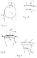
- a web 1 of non-magnetic (magnetically non-conductive) material such as, for example, aluminium, copper, paper, plastic, runs over a cylindrical roller 2, the axis 3 of which is horizontal.
- a transducer 4 mounted in a stand (not shown in greater detail here) above the roller 2 is a transducer 4 for measuring the thickness of the web 1 where it passes over the roller in the direction of the arrow 5.
- the underside 6 of the transducer which is concave and cylindrical, faces towards the web 1 and is located directly above the latter, with a narrow gap 7 between the underside 6 and the web 1.
- the curvature on the underside 6 is selected in such a manner that the underside is coaxial with the roller 2 and thus has its centre of curvature on the axis 3.
- the transducer 4 is mounted with a given mobility in the vertical direction relative to the roller 2. As can be seen in greater detail in Fig. 2, the transducer 4 is held at a predetermined spacing from the web 1 by means of a gas cushion which is produced by gas being introduced into a gas duct 8 for distribution in the underside 6. In this way, gas can flow out in the lateral direction according to the arrows and form a gas cushion which separates the transducer and the web.
- the gas supplied is suitably air, and, by adapting the gas supply, the desired gap size can be achieved and maintained with great accuracy.
- the transducer 4 is a positional transducer and works according to the reluctance principle. It interacts in a known manner with a magnetic (magnetically conductive) reference element on the opposite side of the web 1.
- the reference element consists of the shell 9 of the roller 2.
- Transducers of this type are well-known and have been described in, for example, Swedish patent 7904903-7, for which reason a detailed description of the operation and construction of the transducer is not required in this context. Measurement with respect to the reference element thus takes place according to the reluctance method.
- the gap 7 between the transducer 4 and the web 1 produced by means of the gas cushion can be made as small as 30-100 ⁇ m, depending on the roller diameter and the type of material in the web 1.
- the web 1 of non-magnetic material may be homogeneous but it may also be constructed of a number of different layers.
- a possible example is shown in Fig. 3, where a non-magnetic sheet 10 of, for example, aluminium is coated with a non-magnetic paint layer 11, the thickness of which is to be checked in connection with a painting process. With knowledge of the thickness of the sheet 10, it is possible, using the measuring method described, to check and, if appropriate, control the thickness of the paint layer 11 which thus makes up a given proportion of the thickness of the web 1 as a whole.
- a non-magnetic layer on a magnetic layer of, for example, sheet is also possible to measure and, if appropriate, control the thickness of a non-magnetic layer on a magnetic layer of, for example, sheet.
- a web 1 of non-magnetic material in this case paint
- the sheet 9' has an accurately defined position and can in this way form the reference element for the transducer 4.
- the thickness of the web 1, that is to say the paint layer in this case can in this way be measured in in principle the same manner as in Fig. 2.
- the shell 9 of the roller 2 does not have to be made of magnetic material but can be made of non-magnetic material because of course the magnetic sheet 9' forms the reference element for the transducer 4.
- the thickness of a paint layer may usually amount to approximately 200-300 ⁇ m, but considerably smaller values, down to approximately 10 ⁇ m, can also be found.
- the thickness of the sheet should not exceed approximately 2 mm so that the roller 2 does not have to have too great a diameter. If so desired, however, values other than those stated here are possible, if necessary with reduced accuracy as a result.
Applications Claiming Priority (2)
| Application Number | Priority Date | Filing Date | Title |
|---|---|---|---|
| SE9801551 | 1998-05-04 | ||
| SE9801551A SE9801551L (sv) | 1998-05-04 | 1998-05-04 | Sätt och anordning för mätning av materialtjocklek |
Publications (1)
| Publication Number | Publication Date |
|---|---|
| EP0959324A1 true EP0959324A1 (fr) | 1999-11-24 |
Family
ID=20411177
Family Applications (1)
| Application Number | Title | Priority Date | Filing Date |
|---|---|---|---|
| EP99850073A Withdrawn EP0959324A1 (fr) | 1998-05-04 | 1999-05-04 | Appareil et procédé de mesure de l'épaisseur de matériaux |
Country Status (2)
| Country | Link |
|---|---|
| EP (1) | EP0959324A1 (fr) |
| SE (1) | SE9801551L (fr) |
Citations (5)
| Publication number | Priority date | Publication date | Assignee | Title |
|---|---|---|---|---|
| US2266620A (en) * | 1940-05-28 | 1941-12-16 | Gen Electric | Thickness gauge |
| US3513555A (en) * | 1967-03-30 | 1970-05-26 | Bradstreet J Vachon | Thickness gauging apparatus |
| US3857095A (en) * | 1971-07-26 | 1974-12-24 | Vickers Ltd | Method and apparatus for measuring the thickness of a coating on a substrate |
| US4387339A (en) * | 1979-05-06 | 1983-06-07 | Sunds Defibrator Ab | Method and apparatus for measuring the spacing between the opposed surfaces of separated elements |
| US4752739A (en) * | 1984-10-16 | 1988-06-21 | Stein Heurtey | Device for measuring the thickness of thin metallic layers deposited on a conductive support |
-
1998
- 1998-05-04 SE SE9801551A patent/SE9801551L/ not_active Application Discontinuation
-
1999
- 1999-05-04 EP EP99850073A patent/EP0959324A1/fr not_active Withdrawn
Patent Citations (5)
| Publication number | Priority date | Publication date | Assignee | Title |
|---|---|---|---|---|
| US2266620A (en) * | 1940-05-28 | 1941-12-16 | Gen Electric | Thickness gauge |
| US3513555A (en) * | 1967-03-30 | 1970-05-26 | Bradstreet J Vachon | Thickness gauging apparatus |
| US3857095A (en) * | 1971-07-26 | 1974-12-24 | Vickers Ltd | Method and apparatus for measuring the thickness of a coating on a substrate |
| US4387339A (en) * | 1979-05-06 | 1983-06-07 | Sunds Defibrator Ab | Method and apparatus for measuring the spacing between the opposed surfaces of separated elements |
| US4752739A (en) * | 1984-10-16 | 1988-06-21 | Stein Heurtey | Device for measuring the thickness of thin metallic layers deposited on a conductive support |
Also Published As
| Publication number | Publication date |
|---|---|
| SE9801551L (sv) | 1999-11-05 |
| SE9801551D0 (sv) | 1998-05-04 |
Similar Documents
| Publication | Publication Date | Title |
|---|---|---|
| CN106840033B (zh) | 一种基于图像处理的钢轨廓形检测装置及方法 | |
| FI125343B (fi) | Rainan paksuuden mittauslaite | |
| US6400146B1 (en) | Sensor head for ACFM based crack detection | |
| US6769280B2 (en) | Real-time draw-in sensors and methods of fabrication | |
| CN101784689B (zh) | 用于对在热浸精整设备的整平喷嘴之间引导的具有覆层的带材进行带材稳定的方法和热浸精整设备 | |
| CA1295394C (fr) | Appareil de controle de materiau en bande methode connexe | |
| JP2009502523A (ja) | 研削盤のための独立測定装置 | |
| CA1199945A (fr) | Palpeur de feuille eliminateur de plis | |
| EP0959324A1 (fr) | Appareil et procédé de mesure de l'épaisseur de matériaux | |
| US7423754B2 (en) | Web planarity gauge and method | |
| EP0064325A2 (fr) | Appareil de mesure | |
| US20180266804A1 (en) | Curved gap gauge | |
| US20240033806A1 (en) | Method for determining the thickness of a material strip during the feed of the material strip to the machining zone of a machine tool | |
| US6038779A (en) | Apparatus for measuring thickness and method therefor | |
| JP5131010B2 (ja) | 連続溶融金属メッキシステム及びメッキ方法 | |
| CN111174737B (zh) | 涂覆量的计测方法 | |
| JPH0725615Y2 (ja) | 厚みプロフィール測定装置 | |
| JPH07318301A (ja) | 円筒体の偏肉測定方法及び装置 | |
| JPH05272959A (ja) | ロールプロフィルの測定方法 | |
| JP3950372B2 (ja) | 鋼帯の耳割れ検出方法及び装置 | |
| JP2776339B2 (ja) | 厚み計 | |
| KR102226993B1 (ko) | 소절재의 휨 측정방법 | |
| KR101729454B1 (ko) | 공작물 표면과 스트립 재료 검사 장치 | |
| JPH0462001B2 (fr) | ||
| JPH04248408A (ja) | 塗膜厚さの測定方法 |
Legal Events
| Date | Code | Title | Description |
|---|---|---|---|
| PUAI | Public reference made under article 153(3) epc to a published international application that has entered the european phase |
Free format text: ORIGINAL CODE: 0009012 |
|
| AK | Designated contracting states |
Kind code of ref document: A1 Designated state(s): DE FR GB |
|
| AX | Request for extension of the european patent |
Free format text: AL;LT;LV;MK;RO;SI |
|
| 17P | Request for examination filed |
Effective date: 20000522 |
|
| AKX | Designation fees paid |
Free format text: DE FR GB |
|
| RAP1 | Party data changed (applicant data changed or rights of an application transferred) |
Owner name: DAPROX AB |
|
| 17Q | First examination report despatched |
Effective date: 20040811 |
|
| STAA | Information on the status of an ep patent application or granted ep patent |
Free format text: STATUS: THE APPLICATION IS DEEMED TO BE WITHDRAWN |
|
| 18D | Application deemed to be withdrawn |
Effective date: 20041222 |