EP0959317A1 - Wärmetauscher und Verfahren zu dessen Herstellung - Google Patents
Wärmetauscher und Verfahren zu dessen Herstellung Download PDFInfo
- Publication number
- EP0959317A1 EP0959317A1 EP98109033A EP98109033A EP0959317A1 EP 0959317 A1 EP0959317 A1 EP 0959317A1 EP 98109033 A EP98109033 A EP 98109033A EP 98109033 A EP98109033 A EP 98109033A EP 0959317 A1 EP0959317 A1 EP 0959317A1
- Authority
- EP
- European Patent Office
- Prior art keywords
- holding plate
- tube
- heat
- heat exchanger
- resin
- Prior art date
- Legal status (The legal status is an assumption and is not a legal conclusion. Google has not performed a legal analysis and makes no representation as to the accuracy of the status listed.)
- Granted
Links
- 238000000034 method Methods 0.000 title claims description 17
- 229920005989 resin Polymers 0.000 claims abstract description 113
- 239000011347 resin Substances 0.000 claims abstract description 113
- 239000012530 fluid Substances 0.000 claims description 31
- 238000012546 transfer Methods 0.000 claims description 18
- 238000004519 manufacturing process Methods 0.000 abstract description 3
- 239000007788 liquid Substances 0.000 description 9
- 239000000498 cooling water Substances 0.000 description 8
- 230000000694 effects Effects 0.000 description 5
- 230000001105 regulatory effect Effects 0.000 description 5
- 238000007789 sealing Methods 0.000 description 5
- XLYOFNOQVPJJNP-UHFFFAOYSA-N water Substances O XLYOFNOQVPJJNP-UHFFFAOYSA-N 0.000 description 5
- 230000002708 enhancing effect Effects 0.000 description 4
- 229920001343 polytetrafluoroethylene Polymers 0.000 description 4
- 239000004810 polytetrafluoroethylene Substances 0.000 description 4
- -1 polytetrafluoroethylene Polymers 0.000 description 3
- 239000004743 Polypropylene Substances 0.000 description 2
- 239000004033 plastic Substances 0.000 description 2
- 229920003023 plastic Polymers 0.000 description 2
- 229920000642 polymer Polymers 0.000 description 2
- 229920001155 polypropylene Polymers 0.000 description 2
- 230000008569 process Effects 0.000 description 2
- 239000004812 Fluorinated ethylene propylene Substances 0.000 description 1
- 230000002378 acidificating effect Effects 0.000 description 1
- 230000008859 change Effects 0.000 description 1
- 230000003247 decreasing effect Effects 0.000 description 1
- 238000010586 diagram Methods 0.000 description 1
- 238000005553 drilling Methods 0.000 description 1
- HQQADJVZYDDRJT-UHFFFAOYSA-N ethene;prop-1-ene Chemical group C=C.CC=C HQQADJVZYDDRJT-UHFFFAOYSA-N 0.000 description 1
- 238000002474 experimental method Methods 0.000 description 1
- 238000010438 heat treatment Methods 0.000 description 1
- 238000005259 measurement Methods 0.000 description 1
- 230000005012 migration Effects 0.000 description 1
- 238000013508 migration Methods 0.000 description 1
- 230000000149 penetrating effect Effects 0.000 description 1
- 229920009441 perflouroethylene propylene Polymers 0.000 description 1
- 230000005855 radiation Effects 0.000 description 1
- 239000000126 substance Substances 0.000 description 1
Images


Classifications
-
- B—PERFORMING OPERATIONS; TRANSPORTING
- B29—WORKING OF PLASTICS; WORKING OF SUBSTANCES IN A PLASTIC STATE IN GENERAL
- B29C—SHAPING OR JOINING OF PLASTICS; SHAPING OF MATERIAL IN A PLASTIC STATE, NOT OTHERWISE PROVIDED FOR; AFTER-TREATMENT OF THE SHAPED PRODUCTS, e.g. REPAIRING
- B29C65/00—Joining or sealing of preformed parts, e.g. welding of plastics materials; Apparatus therefor
- B29C65/02—Joining or sealing of preformed parts, e.g. welding of plastics materials; Apparatus therefor by heating, with or without pressure
- B29C65/14—Joining or sealing of preformed parts, e.g. welding of plastics materials; Apparatus therefor by heating, with or without pressure using wave energy, i.e. electromagnetic radiation, or particle radiation
-
- B—PERFORMING OPERATIONS; TRANSPORTING
- B29—WORKING OF PLASTICS; WORKING OF SUBSTANCES IN A PLASTIC STATE IN GENERAL
- B29C—SHAPING OR JOINING OF PLASTICS; SHAPING OF MATERIAL IN A PLASTIC STATE, NOT OTHERWISE PROVIDED FOR; AFTER-TREATMENT OF THE SHAPED PRODUCTS, e.g. REPAIRING
- B29C65/00—Joining or sealing of preformed parts, e.g. welding of plastics materials; Apparatus therefor
- B29C65/02—Joining or sealing of preformed parts, e.g. welding of plastics materials; Apparatus therefor by heating, with or without pressure
-
- B—PERFORMING OPERATIONS; TRANSPORTING
- B29—WORKING OF PLASTICS; WORKING OF SUBSTANCES IN A PLASTIC STATE IN GENERAL
- B29C—SHAPING OR JOINING OF PLASTICS; SHAPING OF MATERIAL IN A PLASTIC STATE, NOT OTHERWISE PROVIDED FOR; AFTER-TREATMENT OF THE SHAPED PRODUCTS, e.g. REPAIRING
- B29C66/00—General aspects of processes or apparatus for joining preformed parts
- B29C66/01—General aspects dealing with the joint area or with the area to be joined
- B29C66/05—Particular design of joint configurations
- B29C66/10—Particular design of joint configurations particular design of the joint cross-sections
- B29C66/11—Joint cross-sections comprising a single joint-segment, i.e. one of the parts to be joined comprising a single joint-segment in the joint cross-section
- B29C66/112—Single lapped joints
- B29C66/1122—Single lap to lap joints, i.e. overlap joints
-
- B—PERFORMING OPERATIONS; TRANSPORTING
- B29—WORKING OF PLASTICS; WORKING OF SUBSTANCES IN A PLASTIC STATE IN GENERAL
- B29C—SHAPING OR JOINING OF PLASTICS; SHAPING OF MATERIAL IN A PLASTIC STATE, NOT OTHERWISE PROVIDED FOR; AFTER-TREATMENT OF THE SHAPED PRODUCTS, e.g. REPAIRING
- B29C66/00—General aspects of processes or apparatus for joining preformed parts
- B29C66/01—General aspects dealing with the joint area or with the area to be joined
- B29C66/05—Particular design of joint configurations
- B29C66/10—Particular design of joint configurations particular design of the joint cross-sections
- B29C66/12—Joint cross-sections combining only two joint-segments; Tongue and groove joints; Tenon and mortise joints; Stepped joint cross-sections
- B29C66/122—Joint cross-sections combining only two joint-segments, i.e. one of the parts to be joined comprising only two joint-segments in the joint cross-section
- B29C66/1222—Joint cross-sections combining only two joint-segments, i.e. one of the parts to be joined comprising only two joint-segments in the joint cross-section comprising at least a lapped joint-segment
-
- B—PERFORMING OPERATIONS; TRANSPORTING
- B29—WORKING OF PLASTICS; WORKING OF SUBSTANCES IN A PLASTIC STATE IN GENERAL
- B29C—SHAPING OR JOINING OF PLASTICS; SHAPING OF MATERIAL IN A PLASTIC STATE, NOT OTHERWISE PROVIDED FOR; AFTER-TREATMENT OF THE SHAPED PRODUCTS, e.g. REPAIRING
- B29C66/00—General aspects of processes or apparatus for joining preformed parts
- B29C66/01—General aspects dealing with the joint area or with the area to be joined
- B29C66/05—Particular design of joint configurations
- B29C66/10—Particular design of joint configurations particular design of the joint cross-sections
- B29C66/12—Joint cross-sections combining only two joint-segments; Tongue and groove joints; Tenon and mortise joints; Stepped joint cross-sections
- B29C66/122—Joint cross-sections combining only two joint-segments, i.e. one of the parts to be joined comprising only two joint-segments in the joint cross-section
- B29C66/1224—Joint cross-sections combining only two joint-segments, i.e. one of the parts to be joined comprising only two joint-segments in the joint cross-section comprising at least a butt joint-segment
-
- B—PERFORMING OPERATIONS; TRANSPORTING
- B29—WORKING OF PLASTICS; WORKING OF SUBSTANCES IN A PLASTIC STATE IN GENERAL
- B29C—SHAPING OR JOINING OF PLASTICS; SHAPING OF MATERIAL IN A PLASTIC STATE, NOT OTHERWISE PROVIDED FOR; AFTER-TREATMENT OF THE SHAPED PRODUCTS, e.g. REPAIRING
- B29C66/00—General aspects of processes or apparatus for joining preformed parts
- B29C66/50—General aspects of joining tubular articles; General aspects of joining long products, i.e. bars or profiled elements; General aspects of joining single elements to tubular articles, hollow articles or bars; General aspects of joining several hollow-preforms to form hollow or tubular articles
- B29C66/51—Joining tubular articles, profiled elements or bars; Joining single elements to tubular articles, hollow articles or bars; Joining several hollow-preforms to form hollow or tubular articles
- B29C66/52—Joining tubular articles, bars or profiled elements
- B29C66/522—Joining tubular articles
- B29C66/5227—Joining tubular articles for forming multi-tubular articles by longitudinally joining elementary tubular articles wall-to-wall (e.g. joining the wall of a first tubular article to the wall of a second tubular article) or for forming multilayer tubular articles
-
- B—PERFORMING OPERATIONS; TRANSPORTING
- B29—WORKING OF PLASTICS; WORKING OF SUBSTANCES IN A PLASTIC STATE IN GENERAL
- B29C—SHAPING OR JOINING OF PLASTICS; SHAPING OF MATERIAL IN A PLASTIC STATE, NOT OTHERWISE PROVIDED FOR; AFTER-TREATMENT OF THE SHAPED PRODUCTS, e.g. REPAIRING
- B29C66/00—General aspects of processes or apparatus for joining preformed parts
- B29C66/50—General aspects of joining tubular articles; General aspects of joining long products, i.e. bars or profiled elements; General aspects of joining single elements to tubular articles, hollow articles or bars; General aspects of joining several hollow-preforms to form hollow or tubular articles
- B29C66/51—Joining tubular articles, profiled elements or bars; Joining single elements to tubular articles, hollow articles or bars; Joining several hollow-preforms to form hollow or tubular articles
- B29C66/53—Joining single elements to tubular articles, hollow articles or bars
- B29C66/534—Joining single elements to open ends of tubular or hollow articles or to the ends of bars
- B29C66/5344—Joining single elements to open ends of tubular or hollow articles or to the ends of bars said single elements being substantially annular, i.e. of finite length, e.g. joining flanges to tube ends
-
- B—PERFORMING OPERATIONS; TRANSPORTING
- B29—WORKING OF PLASTICS; WORKING OF SUBSTANCES IN A PLASTIC STATE IN GENERAL
- B29C—SHAPING OR JOINING OF PLASTICS; SHAPING OF MATERIAL IN A PLASTIC STATE, NOT OTHERWISE PROVIDED FOR; AFTER-TREATMENT OF THE SHAPED PRODUCTS, e.g. REPAIRING
- B29C66/00—General aspects of processes or apparatus for joining preformed parts
- B29C66/50—General aspects of joining tubular articles; General aspects of joining long products, i.e. bars or profiled elements; General aspects of joining single elements to tubular articles, hollow articles or bars; General aspects of joining several hollow-preforms to form hollow or tubular articles
- B29C66/51—Joining tubular articles, profiled elements or bars; Joining single elements to tubular articles, hollow articles or bars; Joining several hollow-preforms to form hollow or tubular articles
- B29C66/53—Joining single elements to tubular articles, hollow articles or bars
- B29C66/534—Joining single elements to open ends of tubular or hollow articles or to the ends of bars
- B29C66/5346—Joining single elements to open ends of tubular or hollow articles or to the ends of bars said single elements being substantially flat
- B29C66/53465—Joining single elements to open ends of tubular or hollow articles or to the ends of bars said single elements being substantially flat said single flat elements being provided with holes facing the tube ends, e.g. for making heat-exchangers
-
- B—PERFORMING OPERATIONS; TRANSPORTING
- B29—WORKING OF PLASTICS; WORKING OF SUBSTANCES IN A PLASTIC STATE IN GENERAL
- B29C—SHAPING OR JOINING OF PLASTICS; SHAPING OF MATERIAL IN A PLASTIC STATE, NOT OTHERWISE PROVIDED FOR; AFTER-TREATMENT OF THE SHAPED PRODUCTS, e.g. REPAIRING
- B29C66/00—General aspects of processes or apparatus for joining preformed parts
- B29C66/50—General aspects of joining tubular articles; General aspects of joining long products, i.e. bars or profiled elements; General aspects of joining single elements to tubular articles, hollow articles or bars; General aspects of joining several hollow-preforms to form hollow or tubular articles
- B29C66/51—Joining tubular articles, profiled elements or bars; Joining single elements to tubular articles, hollow articles or bars; Joining several hollow-preforms to form hollow or tubular articles
- B29C66/54—Joining several hollow-preforms, e.g. half-shells, to form hollow articles, e.g. for making balls, containers; Joining several hollow-preforms, e.g. half-cylinders, to form tubular articles
- B29C66/543—Joining several hollow-preforms, e.g. half-shells, to form hollow articles, e.g. for making balls, containers; Joining several hollow-preforms, e.g. half-cylinders, to form tubular articles joining more than two hollow-preforms to form said hollow articles
- B29C66/5432—Joining several hollow-preforms, e.g. half-shells, to form hollow articles, e.g. for making balls, containers; Joining several hollow-preforms, e.g. half-cylinders, to form tubular articles joining more than two hollow-preforms to form said hollow articles joining hollow covers and hollow bottoms to open ends of container bodies
-
- B—PERFORMING OPERATIONS; TRANSPORTING
- B29—WORKING OF PLASTICS; WORKING OF SUBSTANCES IN A PLASTIC STATE IN GENERAL
- B29C—SHAPING OR JOINING OF PLASTICS; SHAPING OF MATERIAL IN A PLASTIC STATE, NOT OTHERWISE PROVIDED FOR; AFTER-TREATMENT OF THE SHAPED PRODUCTS, e.g. REPAIRING
- B29C66/00—General aspects of processes or apparatus for joining preformed parts
- B29C66/70—General aspects of processes or apparatus for joining preformed parts characterised by the composition, physical properties or the structure of the material of the parts to be joined; Joining with non-plastics material
- B29C66/73—General aspects of processes or apparatus for joining preformed parts characterised by the composition, physical properties or the structure of the material of the parts to be joined; Joining with non-plastics material characterised by the intensive physical properties of the material of the parts to be joined, by the optical properties of the material of the parts to be joined, by the extensive physical properties of the parts to be joined, by the state of the material of the parts to be joined or by the material of the parts to be joined being a thermoplastic or a thermoset
- B29C66/739—General aspects of processes or apparatus for joining preformed parts characterised by the composition, physical properties or the structure of the material of the parts to be joined; Joining with non-plastics material characterised by the intensive physical properties of the material of the parts to be joined, by the optical properties of the material of the parts to be joined, by the extensive physical properties of the parts to be joined, by the state of the material of the parts to be joined or by the material of the parts to be joined being a thermoplastic or a thermoset characterised by the material of the parts to be joined being a thermoplastic or a thermoset
- B29C66/7392—General aspects of processes or apparatus for joining preformed parts characterised by the composition, physical properties or the structure of the material of the parts to be joined; Joining with non-plastics material characterised by the intensive physical properties of the material of the parts to be joined, by the optical properties of the material of the parts to be joined, by the extensive physical properties of the parts to be joined, by the state of the material of the parts to be joined or by the material of the parts to be joined being a thermoplastic or a thermoset characterised by the material of the parts to be joined being a thermoplastic or a thermoset characterised by the material of at least one of the parts being a thermoplastic
- B29C66/73921—General aspects of processes or apparatus for joining preformed parts characterised by the composition, physical properties or the structure of the material of the parts to be joined; Joining with non-plastics material characterised by the intensive physical properties of the material of the parts to be joined, by the optical properties of the material of the parts to be joined, by the extensive physical properties of the parts to be joined, by the state of the material of the parts to be joined or by the material of the parts to be joined being a thermoplastic or a thermoset characterised by the material of the parts to be joined being a thermoplastic or a thermoset characterised by the material of at least one of the parts being a thermoplastic characterised by the materials of both parts being thermoplastics
-
- F—MECHANICAL ENGINEERING; LIGHTING; HEATING; WEAPONS; BLASTING
- F28—HEAT EXCHANGE IN GENERAL
- F28F—DETAILS OF HEAT-EXCHANGE AND HEAT-TRANSFER APPARATUS, OF GENERAL APPLICATION
- F28F21/00—Constructions of heat-exchange apparatus characterised by the selection of particular materials
- F28F21/06—Constructions of heat-exchange apparatus characterised by the selection of particular materials of plastics material
- F28F21/062—Constructions of heat-exchange apparatus characterised by the selection of particular materials of plastics material the heat-exchange apparatus employing tubular conduits
-
- F—MECHANICAL ENGINEERING; LIGHTING; HEATING; WEAPONS; BLASTING
- F28—HEAT EXCHANGE IN GENERAL
- F28F—DETAILS OF HEAT-EXCHANGE AND HEAT-TRANSFER APPARATUS, OF GENERAL APPLICATION
- F28F9/00—Casings; Header boxes; Auxiliary supports for elements; Auxiliary members within casings
- F28F9/02—Header boxes; End plates
- F28F9/04—Arrangements for sealing elements into header boxes or end plates
- F28F9/16—Arrangements for sealing elements into header boxes or end plates by permanent joints, e.g. by rolling
- F28F9/18—Arrangements for sealing elements into header boxes or end plates by permanent joints, e.g. by rolling by welding
- F28F9/187—Arrangements for sealing elements into header boxes or end plates by permanent joints, e.g. by rolling by welding at least one of the parts being non-metallic, e.g. heat-sealing plastic elements
-
- B—PERFORMING OPERATIONS; TRANSPORTING
- B29—WORKING OF PLASTICS; WORKING OF SUBSTANCES IN A PLASTIC STATE IN GENERAL
- B29C—SHAPING OR JOINING OF PLASTICS; SHAPING OF MATERIAL IN A PLASTIC STATE, NOT OTHERWISE PROVIDED FOR; AFTER-TREATMENT OF THE SHAPED PRODUCTS, e.g. REPAIRING
- B29C66/00—General aspects of processes or apparatus for joining preformed parts
- B29C66/70—General aspects of processes or apparatus for joining preformed parts characterised by the composition, physical properties or the structure of the material of the parts to be joined; Joining with non-plastics material
- B29C66/71—General aspects of processes or apparatus for joining preformed parts characterised by the composition, physical properties or the structure of the material of the parts to be joined; Joining with non-plastics material characterised by the composition of the plastics material of the parts to be joined
-
- B—PERFORMING OPERATIONS; TRANSPORTING
- B29—WORKING OF PLASTICS; WORKING OF SUBSTANCES IN A PLASTIC STATE IN GENERAL
- B29L—INDEXING SCHEME ASSOCIATED WITH SUBCLASS B29C, RELATING TO PARTICULAR ARTICLES
- B29L2031/00—Other particular articles
- B29L2031/18—Heat-exchangers or parts thereof
-
- B—PERFORMING OPERATIONS; TRANSPORTING
- B29—WORKING OF PLASTICS; WORKING OF SUBSTANCES IN A PLASTIC STATE IN GENERAL
- B29L—INDEXING SCHEME ASSOCIATED WITH SUBCLASS B29C, RELATING TO PARTICULAR ARTICLES
- B29L2031/00—Other particular articles
- B29L2031/60—Multitubular or multicompartmented articles, e.g. honeycomb
- B29L2031/601—Multi-tubular articles, i.e. composed of a plurality of tubes
- B29L2031/602—Multi-tubular articles, i.e. composed of a plurality of tubes composed of several elementary tubular elements
-
- Y—GENERAL TAGGING OF NEW TECHNOLOGICAL DEVELOPMENTS; GENERAL TAGGING OF CROSS-SECTIONAL TECHNOLOGIES SPANNING OVER SEVERAL SECTIONS OF THE IPC; TECHNICAL SUBJECTS COVERED BY FORMER USPC CROSS-REFERENCE ART COLLECTIONS [XRACs] AND DIGESTS
- Y02—TECHNOLOGIES OR APPLICATIONS FOR MITIGATION OR ADAPTATION AGAINST CLIMATE CHANGE
- Y02P—CLIMATE CHANGE MITIGATION TECHNOLOGIES IN THE PRODUCTION OR PROCESSING OF GOODS
- Y02P80/00—Climate change mitigation technologies for sector-wide applications
- Y02P80/10—Efficient use of energy, e.g. using compressed air or pressurized fluid as energy carrier
-
- Y—GENERAL TAGGING OF NEW TECHNOLOGICAL DEVELOPMENTS; GENERAL TAGGING OF CROSS-SECTIONAL TECHNOLOGIES SPANNING OVER SEVERAL SECTIONS OF THE IPC; TECHNICAL SUBJECTS COVERED BY FORMER USPC CROSS-REFERENCE ART COLLECTIONS [XRACs] AND DIGESTS
- Y10—TECHNICAL SUBJECTS COVERED BY FORMER USPC
- Y10S—TECHNICAL SUBJECTS COVERED BY FORMER USPC CROSS-REFERENCE ART COLLECTIONS [XRACs] AND DIGESTS
- Y10S165/00—Heat exchange
- Y10S165/905—Materials of manufacture
Definitions
- the present invention relates to a heat exchanger employed for exchanging heat between two fluids, for example, one fluid, that is a strong acidic or a strong alkaline medical fluid employed in an Integrated Circuit production line (i.e., IC production line) inside a clean room, or various fluid such as a strong corrosive fluid, and another fluid, that is a heat transfer medium such as a cool medium or a heat medium.
- one fluid that is a strong acidic or a strong alkaline medical fluid employed in an Integrated Circuit production line (i.e., IC production line) inside a clean room
- various fluid such as a strong corrosive fluid
- a heat transfer medium such as a cool medium or a heat medium.
- the present invention relates to a method of producing the same.
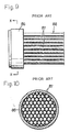
- a cylindrical shell 83 is fixed in a liquid sealing state, between polypropylene-made fixation plates 81 and 82, arranged on either side, connectors 84 and 85 made of PTFE (polytetrafluoroethylene) or PFA (perfluoro-alkoxyfluoro Plastics), having a two steps-cylindrical shape, in a liquid sealing state, and cylindrical sheath rings 86 are fused into the right and left connectors 84 and 85 so that it may be positioned inside the shell 83, a number of fluororesin tubes 87, concretely made of PFA, are gathered for making a bundle, thus forming a tube bundle 88 as a heat transfer pipe.
- PTFE polytetrafluoroethylene
- PFA perfluoro-alkoxyfluoro Plastics
- Both ends arranged longitudinally, of the tube bundle 88 are fixed to the sheath rings 86 by fusing.
- the connectors 85 and 84 have medical fluid paths 89 and 90
- the shell 83 is provided with a cooling water inlet 91 and a cooling water outlet 92 for circulating the cooling water as an example of the heat transfer medium (or heat-exchanging-fluids such as a cool medium or a heat medium).
- a fluid to be heat-exchanged (or a fluid to be cooled or heated) is circulated inside the each fluororesin tube 87 via medical fluid paths 89 and 90 inside the connectors 84 and 85, heat-exchange is conducted between the fluid to be heat-exchanged and a cooling water circulating outside of the tube bundle 88 via the cooling water inlet 91 and the cooling water outlet 92 of the shell 83.
- respective resin tubes 87 are contacted with each other, thus being positioned in a honeycomb structure shown in Figs. 9 and 10. Gaps inevitably formed between the respective resin tubes 87 disposed in such a honeycomb structure, are closed by fusing the resin tubes 87 each other. As a result, gaps formed inevitably between the resin tube 87 and sheath ring 86 are closed by fusing them. Therefore, in the both ends in a longitudinal direction of the tube bundle 88, the respective resin tubes 87 included by the tube bundle 88, are contacted to be in a congested state (i.e, congestion structure) having no gap.
- a congested state i.e, congestion structure
- the resin tubes 87 adjacent to each other are contacted with each other and the ends of the resin tubes 87 are integrally fused into each other, thus decreasing heat emission from the sheath ring 86 and the tube bundle 88 (i.e., tube binding portion) adjacent thereto. Accordingly, there is a problem of hindering a whole of the heat exchanger from being miniaturized in view of keeping heat-exchange efficiency.
- the present invention has been conducted in view of the above mentioned circumstances.
- fusing portions for fusing a number of resin tubes forming the tube bundle into a holding plate have a non-contacted congestion structure wherein the each resin tube is arranged apart without directly contacting with each other. Accordingly, even if the resin tube is swingingly moved under a flow of the heat transfer medium inside a heat exchanging chamber, an excess load is not applied to the fusing portions of the resin tubes, thereby enhancing reliability on connection of the fusing portions.
- Another object of the present invention is to ensure a heat emission space between the resin tubes by the non-contacted congestion structure, thereby providing a heat exchanger having an excellent heat emission property and facilitating miniaturization thereof.
- Further object of the present invention is to enhance the heat emission property in the ends of the resin tubes arranged on tube holding holes of the holding plates, thereby achieving further miniaturization of a whole of the heat exchanger.
- Still another object of the present invention is that all elements of the heat exchanger, such as the holding plates and the resin tubes, are made of a fluororesin.
- Still further object of the present invention is to employ radiant heat emitted from a heat source, so as to integrally fuse the holding plate into the ends of the resin tubes arranged on the tube holding holes of the holding plate.
- a heat exchanger having plural resin tubes for mutually exchanging heat between a fluid flowing inside the heat exchanger and a fluid flowing outside it comprises
- heat-exchange is conducted between the fluid flowing inside the plural resin tubes and the fluid flowing outside it.
- a fluid or a fluid to be heat-exchanged
- a medical fluid is cited
- a heat transfer medium such as a cool medium or a heat medium.
- the respective ends of the plural resin tubes are respectively arranged on plural independent tube holding holes formed on the holding plate, so as to be integrally fused therein.
- a fusing portion for fusing the each resin tube into the holding plate are not contacted with the other fusing portions for fusing the other resin tubes therein. Therefore, each of the plural resin tubes has a non-contacted congestion structure wherein the holding plate is not contacted with the fusing portions. Consequently, even if a specific resin tube is slightly swung and moved under the flow of the heat transfer medium, there is no possibility wherein an excess load is not applied to the each fusing portion of the other resin tube under the swinging flow of the resin tube. Therefore, reliability on connection of the fusing portions is enhanced.
- each resin tube has a non-congested structure at the fusing portions between the resin tubes and the holding plates, over a whole length of the each resin tube, a space therebetween for emitting heat is secured, thereby enhancing the heat emission property of the resin tube and achieving effectively miniaturization of a whole of the heat exchanger. Therefore, the heat exchanger suitable for one used inside the clean room is obtained.
- the each holding plate is preferably provided with a ring-space (or recess) positioned around a periphery of the each resin tube, for emitting heat.
- the heat exchanger according to the present invention having the above function and effect, is provided with the recess formed around the end of the each resin tube arranged on the tube holding holes of the holding plate, for emitting heat, whereby the heat transfer medium additionally enters into the recess, thereby enhancing the heat emission property (or heat-exchange effect) further so as to achieve the further miniaturization of a whole of the heat exchanger.
- a diameter of the tube holding holes arranged on the holding plate is the almost equal to an external diameter of the each end of the each resin tube arranged on the tube holding holes.
- the above condition ensures that the each end of the resin tube arranged on the each tube holding hole of the holding plate is integrally fused into the holding plate (that is, an inner surface of the each tube holding hole), thereby improving the reliability on connection.
- an outer end face of the holding plate and an end surface of the each resin tube having the each end arranged at the each tube holding hole are on the same level.
- the holding plate is provided with recess located around the periphery of the each resin tube, for emitting heat, it is easy to ensure a large area of the each fusing portion between the each end of the each resin tube and the holding plate.
- This invention may have a configuration wherein the holding plates in pairs are disposed, opposite to each other, one end of the resin tube arranged at the tube holding hole of the holding plate on a side is integrally fused into the holding plate, and the other end of the resin tube arranged at the each tube holding hale of the holding plate on the other side is integrally fused into the holding plate.
- a pair of fixation plates disposed oppositely and a cylindrical shell disposed between the fixation plates form a closed heat exchanging chamber
- a pair of cylindrical connectors are separately fitted on the pair of fixation plates
- one holding plate on a side and the other holding plate on the other side are separately fixed to the corresponding connectors by fusing
- an inlet and an outlet for pouring-in and pouring-out the heat transfer medium for communicating with the heat exchanging chamber, and an inlet and an outlet for making a fluid to be heat-exchanged flowing-in on one connector and flowing-out in the other connector are provided.
- the heat-exchange is conducted between the heat transfer medium fed from the inlet to the heat exchanging chamber and the fluid to be heat-exchanged of the inside of the resin tubes, while the medium flows through the heat exchanging chamber. Thereafter, it flows out of the outlet.
- the fluid to be heat-exchanged is fed to the inside of the each resin tube through the inlet of the fluid to be heat-exchanged disposed on one connector before it flows out of the outlet on the other connector.
- All of the elements such as the holding plates, the resin tubes, the fixation plates and the shell may be made of the fluororesin, whereby the heat exchanger itself is excellent in chemicals-resistant and heat-resistant properties owing to characteristic of the fluororesin.
- a method of producing a heat exchanger according to the present invention comprises the steps:
- each tube holding hole formed on the holding plate is divided into a small diameter portion positioned outside the holding plate and a large diameter portion positioned inside it.
- the each end of the resin tube arranged on the small diameter portion is integrally fused into only the small diameter portion by employing radiant heat, whereby the large diameter portion is provided with ring-space for emitting heat located around a periphery of the resin tube, except a fusing portion into the small diameter portion.
- the holding plate In case of employing the producing method, it is possible to employ the holding plate, the resin tubes or the like made of the fluororesin. Moreover, preferably, the radiant heat is applied to an outer surface of the holding plate from the heat source set at intervals.
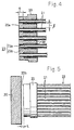
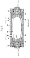
- Figs. 1 and 2 show a heat exchanger employed in a closed clean room or the like.
- the heat exchanger 11 is provided with a heat exchanging chamber 19 including a pair of fixation plates 12, 13 disposed on either side oppositely, and a cylindrical shell 14 disposed between the fixation plate 12 and the other 13, and fixed to the fixation plates 12, 13 in a liquid-sealing state.
- the fixation plates 12, 13 on either side and the shell 14 are firmly joined by tie rods 15 and nuts 16.
- fixation plates 12 and 13 arranged on either side are fixed respectively to connectors 17 and 18 having a multiple-steps-cylindrical shape in configuration, in a liquid sealing state.
- a portion positioned inside the heat exchanging chamber 19 is connected with holding plates 20 as cores by fusing.
- the heat exchanging chamber 19 is provided with a tube bundle 22 having a non-contacted congestion structure or a structure of gathering plural resin tubes 21 by keeping a state wherein the plural resin tubes 21 as heat transfer tubes are not contacted with each other.
- An end and the other end longitudinally positioned at the each resin tube 21 included by the tube bundle 22 are respectively fixed to the holding plates 20 on the either side by a fixing structure as below.
- the end and the other end longitudinally positioned at the each resin tube 21 are fixed to the holding plates 20 on the either side in the same structure.
- the disc-shaped holding plates 20 prior to being fixed to the resin tubes 21, are provided with plural and independent tube holding holes 23 whose diameters are the same as an external diameter of the each resin tube 21, in a lattice arrangement.
- the ends of the plural resin tubes 21 are respectively inserted into the tube holding holes 23, thereby disposing the each end of the resin tubes 21 on the each tube holding hole 23 without any space.
- end surfaces of the resin tubes 21 having the ends thereof disposed on the each tube holding hole 23, and an outer end surface 20a of the holding plate 20 are flatly arranged.
- the end of the resin tube 21 arranged on the each tube holding hole 23 is integrally fused into the each holding plate 20 (i.e., inner side of the tube holding hole 23) by employing radiant heat emitted from a heat source 30 (cf. Fig. 5) described as below.
- the each tube holding hole 23 of the each holding plate 20 is divided into a small diameter portion 23a positioned on a side of an outer surface of the holding plate 20, and a large diameter portion 23b positioned on a side of an inner surface thereof.
- the portion on the small diameter portion 23a is integrally fused into only the small diameter portion 23a by employing radiant heat, and on the other hand, the large diameter portion 23b is formed with ring-spaces 29 located around a periphery of the each resin tube 21 for emitting heat.
- the each holding plate 20 includes the recess 29 located around the periphery of the each resin tube 21, and opened on a side of the heat exchanging chamber 19, for emitting heat.
- a length ⁇ of the fusing portion is shown, and in the present embodiment, the length ⁇ corresponds to a length of the small diameter portion 23a.
- an inlet 24 of a temperature regulating water as an example of heat transfer medium is disposed on one fixation plate 12 of the fixation plates 12 and 13 on the either side, and an outlet 25 is formed on the other fixation plate 13.
- These inlet 24 and outlet 25 are respectively communicated with the heat exchanging chamber 19.
- the both connectors 17 and 18 include flowing paths 27 and 28 for pouring a medical liquid as an example of the heat-exchanged fluid inside them, and the medical liquid as an example of the heat-exchanged fluid flows through the flowing path 28 inside the connector 18, the plural resin tubes 21 and the flowing path 27 inside the connector 17 subsequently.
- Fig. 2 31 and 32 respectively designate a sleeve and a union nut.
- the holding plate 20 is integrally fused into the end of the resin tube 21 arranged on the tube holding hole 23 of the holding plate 20, by employing the radiant heat. Concretely, it may be performed by the method illustrated in Fig. 5.
- the heat source 30 for applying the radiant heat illustrated in Fig. 5 is set, a distance L between the heat source 30 and the outer end surface of the holding plate 20 is predetermined at 1 to 10 mm, preferably 1 to 5 mm, and a temperature of the heat source 30 is predetermined at 400 to 650° C, preferably 450 to 550° C, and after it is heated in 1 to 90 minutes, preferably 1 to 60 minutes, the heat source 30 is taken away so that it is naturally cooled down, thereby fusing the holding plate 20 into the plural resin tubes 21 integrally.
- the heat-exchange is performed between the fluid of the medical liquid or the like flowing through the inside of the plural resin tubes 21 and the temperature regulating water (i.e., the heat transfer medium) flowing through the heat exchanging chamber 19 outside the each resin tubes 21.
- the plural resin tubes 21 are respectively arranged on the plural independent tube holding holes 23 formed on the holding plates 20 on the either side, and a predetermined length range ⁇ in a longitudinal direction of the each resin tube 21 from the end surface thereof is integrally fused into the holding plates 20, thereby forming a non-contacted congestion structure.
- Fig. 7 is a partially enlarged view of enlarging only main portions, illustrating another embodiment of the heat exchanger.
- the each tube holding hole 23 penetrating the holding plate 20 as a core is disposed, a whole of the end of the resin tube 21 arranged by inserting in the tube holding hole 23 is subjected to a heating process by means of the above radiant heat, thus forming the each fusing portion having a predetermined length ⁇ .
- this embodiment has the almost same functions and effects as the above previous embodiment, whereby elements in Fig. 7 identical to ones in Fig. 4 are designated to the same reference numerals, and the detail description thereof are omitted.
- the resin tube 21 may be made of a resin
- the fixation plates 12, 13 and the shell 14 and connector 17, 18 and the holding plates 20, 20 may be made of a resin.
- the tie rods 15 and the nuts 16 may be made of a resin.
- the each element is made of a resin, polypropylene polymers or a fluororesin may be suitably employed.
- fluororesin concretely PFA (perfluoro-alkoxyfluoro plastics), PTFE (polytetrafluoroetylene), denatured-PTFE, FEP (fluorinated ethylene propylene resin), ETFE (etylene-tryfluoro-etylene), CTFE (chioro-tryfluoro-etylene), ECTFE (etylene-chloro-tryfluoro-etylene) may be preferably employed.
- Seal rings 41 and 42 or the like for keeping sealing property of connecting portion of each member shown in Fig. 2 may be also made of the fluororesin as mentioned above.
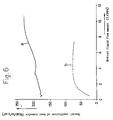
- Fig. 6 shows a measuring result wherein an outer size and a tube size of the each heat exchanger are identically predetermined, and a heat migration amount per a unit area, a unit time, and a unit temperature of the surface of the tube is actually measured as an overall coefficient of heat transfer under the same condition.
- the number of tubes is 85 in the present embodiment, and 331 in the conventional one.
- a medical liquid flow amount is shown in a horizontal axis, and the overall coefficient of heat transfer is shown in a vertical axis with the result that a property "a" of the present embodiment is compared with a property "b" of the conventional one.
- An experiment result in Fig. 6 is obtained as to a heat exchanger having the fixation plates 12, 13 made of polypropylene polymers, and the connectors 17, 18, the holding plates 20, the resin tubes 21, the sleeves 31, the union nuts 32 made of PFA.
- the heat exchanger 11 of the present embodiment has achieved the overall coefficient of heat transfer which is twice or three times the conventional ones, comparing the present embodiment with the conventional one, thus enhancing heat-exchange efficiency, which leads to contributing to miniaturization of an entire heat exchanger 11.
Landscapes
- Engineering & Computer Science (AREA)
- Mechanical Engineering (AREA)
- Physics & Mathematics (AREA)
- Thermal Sciences (AREA)
- General Engineering & Computer Science (AREA)
- Health & Medical Sciences (AREA)
- Electromagnetism (AREA)
- Toxicology (AREA)
- Heat-Exchange Devices With Radiators And Conduit Assemblies (AREA)
- Details Of Heat-Exchange And Heat-Transfer (AREA)
- Lining Or Joining Of Plastics Or The Like (AREA)
Priority Applications (5)
| Application Number | Priority Date | Filing Date | Title |
|---|---|---|---|
| JP8331473A JP3059393B2 (ja) | 1996-11-26 | 1996-11-26 | 熱交換器 |
| US09/076,863 US6269871B1 (en) | 1996-11-26 | 1998-05-13 | Heat exchanger and a method of producing the same |
| AT98109033T ATE246333T1 (de) | 1998-05-18 | 1998-05-18 | Wärmetauscher und verfahren zu dessen herstellung |
| DE69816787T DE69816787T2 (de) | 1998-05-18 | 1998-05-18 | Wärmetauscher und Verfahren zu dessen Herstellung |
| EP98109033A EP0959317B1 (de) | 1996-11-26 | 1998-05-18 | Wärmetauscher und Verfahren zu dessen Herstellung |
Applications Claiming Priority (3)
| Application Number | Priority Date | Filing Date | Title |
|---|---|---|---|
| JP8331473A JP3059393B2 (ja) | 1996-11-26 | 1996-11-26 | 熱交換器 |
| US09/076,863 US6269871B1 (en) | 1996-11-26 | 1998-05-13 | Heat exchanger and a method of producing the same |
| EP98109033A EP0959317B1 (de) | 1996-11-26 | 1998-05-18 | Wärmetauscher und Verfahren zu dessen Herstellung |
Publications (2)
| Publication Number | Publication Date |
|---|---|
| EP0959317A1 true EP0959317A1 (de) | 1999-11-24 |
| EP0959317B1 EP0959317B1 (de) | 2003-07-30 |
Family
ID=27239067
Family Applications (1)
| Application Number | Title | Priority Date | Filing Date |
|---|---|---|---|
| EP98109033A Expired - Lifetime EP0959317B1 (de) | 1996-11-26 | 1998-05-18 | Wärmetauscher und Verfahren zu dessen Herstellung |
Country Status (3)
| Country | Link |
|---|---|
| US (1) | US6269871B1 (de) |
| EP (1) | EP0959317B1 (de) |
| JP (1) | JP3059393B2 (de) |
Cited By (2)
| Publication number | Priority date | Publication date | Assignee | Title |
|---|---|---|---|---|
| WO2003093754A1 (en) * | 2002-04-30 | 2003-11-13 | E.I. Du Pont De Nemours And Company | Device and method for trimming and securing flexible tubes within a structure and articles made therefrom |
| US7695026B2 (en) | 2003-05-16 | 2010-04-13 | Nippon Pillar Packing Co., Ltd. | Tube device, and piping system including the tube device |
Families Citing this family (20)
| Publication number | Priority date | Publication date | Assignee | Title |
|---|---|---|---|---|
| US6804965B2 (en) | 2003-02-12 | 2004-10-19 | Applied Integrated Systems, Inc. | Heat exchanger for high purity and corrosive fluids |
| JP2005030673A (ja) * | 2003-07-11 | 2005-02-03 | Mayekawa Mfg Co Ltd | 熱交換器及びその製造方法 |
| US7458222B2 (en) * | 2004-07-12 | 2008-12-02 | Purity Solutions Llc | Heat exchanger apparatus for a recirculation loop and related methods and systems |
| US20060005955A1 (en) * | 2004-07-12 | 2006-01-12 | Orr Troy J | Heat exchanger apparatus and methods for controlling the temperature of a high purity, re-circulating liquid |
| JP4029092B2 (ja) | 2004-10-26 | 2008-01-09 | 日本ピラー工業株式会社 | 流体用ヒータ及び流体加熱装置 |
| WO2006059498A1 (ja) * | 2004-11-30 | 2006-06-08 | Matsushita Electric Industrial Co., Ltd. | 熱交換器及びその製造方法 |
| CA2538761A1 (en) * | 2005-03-08 | 2006-09-08 | Anthony Joseph Cesaroni | Method for sealing heat exchanger tubes |
| US7870751B2 (en) * | 2005-03-11 | 2011-01-18 | Tokyo Electron Limited | Temperature control system and substrate processing apparatus |
| JP5191768B2 (ja) * | 2008-03-25 | 2013-05-08 | 株式会社ヒロ | 熱交換装置 |
| US8177932B2 (en) * | 2009-02-27 | 2012-05-15 | International Mezzo Technologies, Inc. | Method for manufacturing a micro tube heat exchanger |
| US8410393B2 (en) | 2010-05-24 | 2013-04-02 | Lam Research Corporation | Apparatus and method for temperature control of a semiconductor substrate support |
| TWI392580B (zh) * | 2010-07-09 | 2013-04-11 | Allied Supreme Corp | Fluorine resin pipe joint manufacturing method |
| JP5802006B2 (ja) * | 2010-11-22 | 2015-10-28 | 株式会社日本イトミック | 熱交換器およびその接続方法 |
| US8573285B2 (en) * | 2011-03-24 | 2013-11-05 | Richard O. Rhodes | Polymer manifold and polymer heat exchanger |
| WO2013144074A1 (en) * | 2012-03-26 | 2013-10-03 | Solvay Specialty Polymers Italy S.P.A. | Fluoropolymer pipe |
| CN102744879B (zh) * | 2012-07-20 | 2014-08-27 | 株洲宏大高分子材料有限公司 | 一种氟塑料换热器的薄壁微管的焊接方法及装置 |
| JP6151626B2 (ja) * | 2013-10-25 | 2017-06-21 | 株式会社荏原製作所 | 熱交換器用の流路の接続装置 |
| KR101418089B1 (ko) * | 2013-11-28 | 2014-07-09 | 주식회사 플로우포스 | 열교환 장치 및 그 제조방법 |
| FI126014B (fi) * | 2014-03-04 | 2016-05-31 | Uponor Infra Oy | Matalan lämpötilan lämmönvaihdin |
| CN106985398A (zh) * | 2017-05-09 | 2017-07-28 | 兰州兰石集团有限公司 | 氟塑料热交换器管板焊接装置及焊接方法 |
Citations (7)
| Publication number | Priority date | Publication date | Assignee | Title |
|---|---|---|---|---|
| US3804161A (en) * | 1972-11-24 | 1974-04-16 | Rheem Mfg Co | Non-metallic heat exchanger |
| DE8611642U1 (de) * | 1986-04-28 | 1987-08-13 | Akzo Patente GmbH, 42103 Wuppertal | Wärmetauscher |
| EP0243575A2 (de) * | 1986-04-28 | 1987-11-04 | Akzo N.V. | Wärme- und/oder Stoffaustauscher und Verfahren zum Herstellen von Wärme- und/oder Stoffaustauscher |
| EP0299182A2 (de) * | 1987-07-15 | 1989-01-18 | Akzo N.V. | Verfahren zum Verschweissen von Rohrenden mit einem Rohrboden |
| EP0331023A1 (de) * | 1988-03-01 | 1989-09-06 | Akzo Nobel N.V. | Verfahren zur Herstellung eines Rohrbodens für Wärme- und/oder Stoffaustauscher |
| WO1993016346A1 (en) * | 1992-02-06 | 1993-08-19 | Aalander Johan | A method for manufacturing heat exchangers |
| WO1997028952A1 (en) * | 1996-02-07 | 1997-08-14 | Anthony Joseph Cesaroni | Bonding of tubes into articles |
Family Cites Families (8)
| Publication number | Priority date | Publication date | Assignee | Title |
|---|---|---|---|---|
| US2056920A (en) * | 1935-07-17 | 1936-10-06 | Gen Motors Corp | Heat exchanger for refrigerating systems |
| DE1103944B (de) * | 1957-02-21 | 1961-04-06 | Ver Kesselwerke Ag | Waermeaustauscher, insbesondere aus hochlegiertem Stahl mit in den Rohrboeden eingeschweissten Rohren |
| FR1235426A (fr) * | 1959-05-26 | 1960-07-08 | Loire Atel Forges | échangeur de chaleur |
| US3489209A (en) * | 1968-12-23 | 1970-01-13 | Herbert G Johnson | Heat exchanger having plastic and metal components |
| BE757311A (fr) * | 1969-10-13 | 1971-03-16 | North American Rockwell | Systeme de protection pour generateur de vapeur |
| US4735261A (en) * | 1982-09-13 | 1988-04-05 | Plascore, Inc. | Plastic heat exchanger |
| EP0226825B1 (de) * | 1985-12-16 | 1990-08-29 | Akzo N.V. | Verbinden von Hohlprofilkörpern mit einer Kunststoffplatte, insbesondere zum Herstellen von Wärmetauschern |
| DE3614339A1 (de) * | 1986-04-28 | 1987-10-29 | Akzo Gmbh | Waermetauscher und verfahren zum herstellen von waermetauschern |
-
1996
- 1996-11-26 JP JP8331473A patent/JP3059393B2/ja not_active Expired - Fee Related
-
1998
- 1998-05-13 US US09/076,863 patent/US6269871B1/en not_active Expired - Fee Related
- 1998-05-18 EP EP98109033A patent/EP0959317B1/de not_active Expired - Lifetime
Patent Citations (7)
| Publication number | Priority date | Publication date | Assignee | Title |
|---|---|---|---|---|
| US3804161A (en) * | 1972-11-24 | 1974-04-16 | Rheem Mfg Co | Non-metallic heat exchanger |
| DE8611642U1 (de) * | 1986-04-28 | 1987-08-13 | Akzo Patente GmbH, 42103 Wuppertal | Wärmetauscher |
| EP0243575A2 (de) * | 1986-04-28 | 1987-11-04 | Akzo N.V. | Wärme- und/oder Stoffaustauscher und Verfahren zum Herstellen von Wärme- und/oder Stoffaustauscher |
| EP0299182A2 (de) * | 1987-07-15 | 1989-01-18 | Akzo N.V. | Verfahren zum Verschweissen von Rohrenden mit einem Rohrboden |
| EP0331023A1 (de) * | 1988-03-01 | 1989-09-06 | Akzo Nobel N.V. | Verfahren zur Herstellung eines Rohrbodens für Wärme- und/oder Stoffaustauscher |
| WO1993016346A1 (en) * | 1992-02-06 | 1993-08-19 | Aalander Johan | A method for manufacturing heat exchangers |
| WO1997028952A1 (en) * | 1996-02-07 | 1997-08-14 | Anthony Joseph Cesaroni | Bonding of tubes into articles |
Cited By (2)
| Publication number | Priority date | Publication date | Assignee | Title |
|---|---|---|---|---|
| WO2003093754A1 (en) * | 2002-04-30 | 2003-11-13 | E.I. Du Pont De Nemours And Company | Device and method for trimming and securing flexible tubes within a structure and articles made therefrom |
| US7695026B2 (en) | 2003-05-16 | 2010-04-13 | Nippon Pillar Packing Co., Ltd. | Tube device, and piping system including the tube device |
Also Published As
| Publication number | Publication date |
|---|---|
| EP0959317B1 (de) | 2003-07-30 |
| US6269871B1 (en) | 2001-08-07 |
| JP3059393B2 (ja) | 2000-07-04 |
| JPH10160362A (ja) | 1998-06-19 |
Similar Documents
| Publication | Publication Date | Title |
|---|---|---|
| US6269871B1 (en) | Heat exchanger and a method of producing the same | |
| US7822326B2 (en) | Hybrid heater | |
| US6456785B1 (en) | Resistance heating element | |
| CN102216718B (zh) | 换热器 | |
| CN102667360B (zh) | 用于泄漏敏感应用的双壁轴流式电加热器 | |
| CN1321729C (zh) | 交叉元件的组件及其构建的方法 | |
| KR20010043366A (ko) | 납땜 성능이 개선된 열교환기 매니폴드 블록 | |
| JP6560645B2 (ja) | 配管継手を用いた配管システム | |
| EP1328790B1 (de) | Thermischer austauscher des typs röhre in röhre für flüssigkeitschromatographiesysteme | |
| JP3017683B2 (ja) | 熱交換器 | |
| CN108225063A (zh) | 一种三介质换热器及其制造方法、一种三介质换热设备 | |
| KR100353600B1 (ko) | 열교환기및열교환기의제조방법 | |
| WO2003085344A1 (en) | Heat exchanger assembly | |
| US4977955A (en) | Heat-transfer wall composed of two plate-like parts | |
| JPH02240489A (ja) | 多角形チューブおよび集束チューブ | |
| JPH04356689A (ja) | 自然対流式熱交換器用の放熱管およびその製造方法 | |
| JP2001116475A (ja) | 暖房用放熱器とその製造法 | |
| JPH1047883A (ja) | 熱交換器 | |
| KR970001179Y1 (ko) | 사우나용 방열기 | |
| KR100708614B1 (ko) | 오일쿨러가 내장된 알루미늄재 라디에이터 | |
| JPS58144714A (ja) | 電磁流量計の測定管製造方法 | |
| KR0135562B1 (ko) | 공기조화기용 열교환기 | |
| JP4631224B2 (ja) | 熱交換器 | |
| JP2003075080A (ja) | 熱交換器 | |
| GB2172695A (en) | Heat exchanger |
Legal Events
| Date | Code | Title | Description |
|---|---|---|---|
| PUAI | Public reference made under article 153(3) epc to a published international application that has entered the european phase |
Free format text: ORIGINAL CODE: 0009012 |
|
| 17P | Request for examination filed |
Effective date: 19980618 |
|
| AK | Designated contracting states |
Kind code of ref document: A1 Designated state(s): AT DE FR GB IT NL |
|
| AX | Request for extension of the european patent |
Free format text: AL;LT;LV;MK;RO;SI |
|
| AKX | Designation fees paid |
Free format text: AT DE FR GB IT NL |
|
| 17Q | First examination report despatched |
Effective date: 20010810 |
|
| GRAH | Despatch of communication of intention to grant a patent |
Free format text: ORIGINAL CODE: EPIDOS IGRA |
|
| GRAH | Despatch of communication of intention to grant a patent |
Free format text: ORIGINAL CODE: EPIDOS IGRA |
|
| GRAA | (expected) grant |
Free format text: ORIGINAL CODE: 0009210 |
|
| AK | Designated contracting states |
Designated state(s): AT DE FR GB IT NL |
|
| REG | Reference to a national code |
Ref country code: GB Ref legal event code: FG4D |
|
| REF | Corresponds to: |
Ref document number: 69816787 Country of ref document: DE Date of ref document: 20030904 Kind code of ref document: P |
|
| ET | Fr: translation filed | ||
| PLBE | No opposition filed within time limit |
Free format text: ORIGINAL CODE: 0009261 |
|
| STAA | Information on the status of an ep patent application or granted ep patent |
Free format text: STATUS: NO OPPOSITION FILED WITHIN TIME LIMIT |
|
| 26N | No opposition filed |
Effective date: 20040504 |
|
| PGFP | Annual fee paid to national office [announced via postgrant information from national office to epo] |
Ref country code: NL Payment date: 20090527 Year of fee payment: 12 |
|
| PGFP | Annual fee paid to national office [announced via postgrant information from national office to epo] |
Ref country code: IT Payment date: 20090525 Year of fee payment: 12 Ref country code: FR Payment date: 20090513 Year of fee payment: 12 Ref country code: DE Payment date: 20090525 Year of fee payment: 12 Ref country code: AT Payment date: 20090515 Year of fee payment: 12 |
|
| PGFP | Annual fee paid to national office [announced via postgrant information from national office to epo] |
Ref country code: GB Payment date: 20090522 Year of fee payment: 12 |
|
| REG | Reference to a national code |
Ref country code: NL Ref legal event code: V1 Effective date: 20101201 |
|
| GBPC | Gb: european patent ceased through non-payment of renewal fee |
Effective date: 20100518 |
|
| PG25 | Lapsed in a contracting state [announced via postgrant information from national office to epo] |
Ref country code: AT Free format text: LAPSE BECAUSE OF NON-PAYMENT OF DUE FEES Effective date: 20100518 |
|
| REG | Reference to a national code |
Ref country code: FR Ref legal event code: ST Effective date: 20110131 |
|
| PG25 | Lapsed in a contracting state [announced via postgrant information from national office to epo] |
Ref country code: IT Free format text: LAPSE BECAUSE OF NON-PAYMENT OF DUE FEES Effective date: 20100518 Ref country code: NL Free format text: LAPSE BECAUSE OF NON-PAYMENT OF DUE FEES Effective date: 20101201 |
|
| PG25 | Lapsed in a contracting state [announced via postgrant information from national office to epo] |
Ref country code: DE Free format text: LAPSE BECAUSE OF NON-PAYMENT OF DUE FEES Effective date: 20101201 |
|
| PG25 | Lapsed in a contracting state [announced via postgrant information from national office to epo] |
Ref country code: FR Free format text: LAPSE BECAUSE OF NON-PAYMENT OF DUE FEES Effective date: 20100531 |
|
| PG25 | Lapsed in a contracting state [announced via postgrant information from national office to epo] |
Ref country code: GB Free format text: LAPSE BECAUSE OF NON-PAYMENT OF DUE FEES Effective date: 20100518 |