EP0959295A2 - Luminaire - Google Patents
Luminaire Download PDFInfo
- Publication number
- EP0959295A2 EP0959295A2 EP99201511A EP99201511A EP0959295A2 EP 0959295 A2 EP0959295 A2 EP 0959295A2 EP 99201511 A EP99201511 A EP 99201511A EP 99201511 A EP99201511 A EP 99201511A EP 0959295 A2 EP0959295 A2 EP 0959295A2
- Authority
- EP
- European Patent Office
- Prior art keywords
- lamellae
- reflectors
- luminaire
- outer edge
- inner edge
- Prior art date
- Legal status (The legal status is an assumption and is not a legal conclusion. Google has not performed a legal analysis and makes no representation as to the accuracy of the status listed.)
- Granted
Links
Images


Classifications
-
- F—MECHANICAL ENGINEERING; LIGHTING; HEATING; WEAPONS; BLASTING
- F21—LIGHTING
- F21V—FUNCTIONAL FEATURES OR DETAILS OF LIGHTING DEVICES OR SYSTEMS THEREOF; STRUCTURAL COMBINATIONS OF LIGHTING DEVICES WITH OTHER ARTICLES, NOT OTHERWISE PROVIDED FOR
- F21V11/00—Screens not covered by groups F21V1/00, F21V3/00, F21V7/00 or F21V9/00
- F21V11/02—Screens not covered by groups F21V1/00, F21V3/00, F21V7/00 or F21V9/00 using parallel laminae or strips, e.g. of Venetian-blind type
Definitions
- the smaller volume of the lamellae with a convex inner edge also leads to a smaller material content. This is an important aspect regarding the cost price of the luminaire. If the lamellae are manufactured by cutting, for example punching, them from strip material, then the convex inner edge of the lamellae causes the amount of waste material to be reduced.
- the lamellae are inextricably connected to the reflectors in that they are passed through slits in the reflectors and are subsequently fixed, for example by bending them behind the reflectors.
Abstract
Description
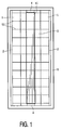
- concave, elongated reflectors which are arranged so as to be essentially opposite and parallel to each other, and which reflectors limit, with a longitudinal edge, a luminous window;
- means for accommodating an elongated electric lamp between the reflectors;
- a plurality of flat, light-scattering lamellae between the reflectors, transverse to the reflectors and transverse to the luminous window, which lamellae have an inner edge and a concave outer edge in the luminous window.
Claims (8)
- A luminaire comprising:characterized in that the inner edge (11) of the lamellae (10) is convex.concave, elongated reflectors (1) which are arranged so as to be essentially opposite and parallel to each other, and which reflectors limit, with a longitudinal edge (2), a luminous window (3);means (4) for accommodating an elongated electric lamp e.1. between the reflectors;a plurality of flat, light-scattering lamellae (10) between the reflectors (1), transverse to the reflectors (1) and transverse to the luminous window (3), which lamellae (10) have an inner edge (11) and a concave outer edge (12) in the luminous window (3),
- A luminaire as claimed in claim 1, characterized in that the inner edge (11) and the outer edge (12) of the lamellae (10) are essentially parallel.
- A luminaire as claimed in claim 1, characterized in that, in the direction of the reflectors (1), the inner edge (11) of the lamellae (10) narrows towards the outer edge (12).
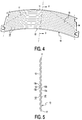
- A luminaire as claimed in claim 1 or 2, characterized in that the lamellae (10) have profiled surfaces (10').
- A luminaire as claimed in claim 4, characterized in that the lamellae (10) comprise folds (13) with an amplitude, which extend along the outer edge (12).
- A luminaire as claimed in claim 5, characterized in that the amplitude of the folds (13) decreases towards the outer edge (12).
- A luminaire as claimed in claim 4, characterized in that the surfaces (10') of the lamellae have dents (15a) and bulges (15b).
- A luminaire as claimed in claim 4, characterized in that the lamellae (10) project from slits (5) in the reflectors (1) and are fixed therein, and in that the profile is only present between the reflectors (1).
Priority Applications (1)
| Application Number | Priority Date | Filing Date | Title |
|---|---|---|---|
| EP99201511A EP0959295B1 (en) | 1998-05-19 | 1999-05-14 | Luminaire |
Applications Claiming Priority (3)
| Application Number | Priority Date | Filing Date | Title |
|---|---|---|---|
| EP98201662 | 1998-05-19 | ||
| EP98201662 | 1998-05-19 | ||
| EP99201511A EP0959295B1 (en) | 1998-05-19 | 1999-05-14 | Luminaire |
Publications (3)
| Publication Number | Publication Date |
|---|---|
| EP0959295A2 true EP0959295A2 (en) | 1999-11-24 |
| EP0959295A3 EP0959295A3 (en) | 2000-08-23 |
| EP0959295B1 EP0959295B1 (en) | 2006-10-04 |
Family
ID=8233738
Family Applications (1)
| Application Number | Title | Priority Date | Filing Date |
|---|---|---|---|
| EP99201511A Expired - Lifetime EP0959295B1 (en) | 1998-05-19 | 1999-05-14 | Luminaire |
Country Status (4)
| Country | Link |
|---|---|
| US (1) | US6220729B1 (en) |
| EP (1) | EP0959295B1 (en) |
| DE (1) | DE69933410T2 (en) |
| ES (1) | ES2272038T3 (en) |
Cited By (2)
| Publication number | Priority date | Publication date | Assignee | Title |
|---|---|---|---|---|
| EP1672274A1 (en) * | 2004-12-20 | 2006-06-21 | SLI France | Luminaire with a plurality of reflecting louvre slats |
| WO2023061926A1 (en) | 2021-10-12 | 2023-04-20 | Signify Holding B.V. | A light emitting device |
Families Citing this family (8)
| Publication number | Priority date | Publication date | Assignee | Title |
|---|---|---|---|---|
| WO2000066948A1 (en) * | 1999-04-28 | 2000-11-09 | Koninklijke Philips Electronics N.V. | Luminaire with lamellae having a gradual change in their profiles |
| CN1625667B (en) * | 2002-01-28 | 2012-12-05 | 皇家飞利浦电子股份有限公司 | Luminaire with lamellas for tubular lamp |
| US7523765B2 (en) * | 2004-02-27 | 2009-04-28 | Fiberspar Corporation | Fiber reinforced spoolable pipe |
| US20050201103A1 (en) * | 2004-03-12 | 2005-09-15 | Honeywell International Inc. | Luminaires with batwing light distribution |
| EP1747398A1 (en) * | 2004-05-07 | 2007-01-31 | Koninklijke Philips Electronics N.V. | Luminaire and lamellae louver therefor |
| CN101057102A (en) * | 2004-11-12 | 2007-10-17 | 皇家飞利浦电子股份有限公司 | Luminaire and lamellae louver therefor |
| US7455431B2 (en) * | 2005-03-11 | 2008-11-25 | Richard Brower | High efficiency light fixture |
| DE102007017343B4 (en) * | 2007-04-12 | 2010-05-12 | Airbus Deutschland Gmbh | Reading light with stray light suppression |
Citations (3)
| Publication number | Priority date | Publication date | Assignee | Title |
|---|---|---|---|---|
| DE3002137B1 (en) * | 1980-01-22 | 1981-06-11 | Philips Patentverwaltung Gmbh, 2000 Hamburg | Luminaire grid |
| EP0138747A1 (en) * | 1983-10-18 | 1985-04-24 | Semperlux GmbH | Parabolic strip element for elongated lamps |
| DE4109492A1 (en) * | 1991-03-22 | 1992-09-24 | Parol Leuchtenkomponenten Gmbh | Light raster for tubular discharge lamp - uses mirrored pairs of lamella elements beneath lamp tube |
Family Cites Families (3)
| Publication number | Priority date | Publication date | Assignee | Title |
|---|---|---|---|---|
| AT381577B (en) * | 1983-04-08 | 1986-11-10 | Bartenbach Christian | GLARE-FREE LAMP FOR A ROD-SHAPED LIGHT SOURCE |
| NZ300261A (en) | 1995-02-14 | 1997-11-24 | Philips Electronics Nv | Luminaire with lamellae having concave outer edges for providing more uniform illumination |
| US5528478A (en) * | 1995-10-04 | 1996-06-18 | Cooper Industries, Inc. | Lighting fixture having a parabolic louver |
-
1999
- 1999-05-14 ES ES99201511T patent/ES2272038T3/en not_active Expired - Lifetime
- 1999-05-14 DE DE69933410T patent/DE69933410T2/en not_active Expired - Lifetime
- 1999-05-14 EP EP99201511A patent/EP0959295B1/en not_active Expired - Lifetime
- 1999-05-17 US US09/313,036 patent/US6220729B1/en not_active Expired - Fee Related
Patent Citations (3)
| Publication number | Priority date | Publication date | Assignee | Title |
|---|---|---|---|---|
| DE3002137B1 (en) * | 1980-01-22 | 1981-06-11 | Philips Patentverwaltung Gmbh, 2000 Hamburg | Luminaire grid |
| EP0138747A1 (en) * | 1983-10-18 | 1985-04-24 | Semperlux GmbH | Parabolic strip element for elongated lamps |
| DE4109492A1 (en) * | 1991-03-22 | 1992-09-24 | Parol Leuchtenkomponenten Gmbh | Light raster for tubular discharge lamp - uses mirrored pairs of lamella elements beneath lamp tube |
Cited By (2)
| Publication number | Priority date | Publication date | Assignee | Title |
|---|---|---|---|---|
| EP1672274A1 (en) * | 2004-12-20 | 2006-06-21 | SLI France | Luminaire with a plurality of reflecting louvre slats |
| WO2023061926A1 (en) | 2021-10-12 | 2023-04-20 | Signify Holding B.V. | A light emitting device |
Also Published As
| Publication number | Publication date |
|---|---|
| DE69933410D1 (en) | 2006-11-16 |
| ES2272038T3 (en) | 2007-04-16 |
| EP0959295B1 (en) | 2006-10-04 |
| EP0959295A3 (en) | 2000-08-23 |
| US6220729B1 (en) | 2001-04-24 |
| DE69933410T2 (en) | 2007-08-02 |
Similar Documents
| Publication | Publication Date | Title |
|---|---|---|
| EP0757772B1 (en) | Luminaire | |
| US4517631A (en) | Indirect light reflector | |
| EP1094272A2 (en) | A lighting appliance | |
| EP0959295B1 (en) | Luminaire | |
| CA2180712C (en) | Lighting fixture having a parabolic louver | |
| AU5737499A (en) | Light with a light-guiding element | |
| US7108398B2 (en) | Luminaire and lamellae grid | |
| EP0862713B1 (en) | Luminaire | |
| EP1606552B1 (en) | Luminaire | |
| EP1151227B1 (en) | Luminaire without lamellae | |
| US6764199B2 (en) | Light distributor, lighting device comprising at least one light distributor and method for the production of a light distributor | |
| BE905874A (en) | INTERIOR LIGHT SPOTS PROTECTIVE LIGHTING UNIT WITH MIRROR REFLECTORS. | |
| EP1815183B1 (en) | Luminaire and lamellae louver therefor | |
| EP1090253B1 (en) | Luminaire with lamellae having a gradual change in their profiles | |
| US20070223229A1 (en) | Luminaire and Lamellae Louver Therefor | |
| JP2003515239A (en) | Anti-glare transparent screen for light emitter | |
| JP4353896B2 (en) | Lighting apparatus and lamellar louver therefor | |
| JPH0322304A (en) | Lighting device | |
| JPH07326215A (en) | Luminaire |
Legal Events
| Date | Code | Title | Description |
|---|---|---|---|
| PUAI | Public reference made under article 153(3) epc to a published international application that has entered the european phase |
Free format text: ORIGINAL CODE: 0009012 |
|
| AK | Designated contracting states |
Kind code of ref document: A2 Designated state(s): BE DE ES FR GB IT NL |
|
| AX | Request for extension of the european patent |
Free format text: AL;LT;LV;MK;RO;SI |
|
| PUAL | Search report despatched |
Free format text: ORIGINAL CODE: 0009013 |
|
| AK | Designated contracting states |
Kind code of ref document: A3 Designated state(s): AT BE CH CY DE DK ES FI FR GB GR IE IT LI LU MC NL PT SE |
|
| AX | Request for extension of the european patent |
Free format text: AL;LT;LV;MK;RO;SI |
|
| RIC1 | Information provided on ipc code assigned before grant |
Free format text: 7F 21V 11/02 A, 7F 21V 13/10 B |
|
| 17P | Request for examination filed |
Effective date: 20010223 |
|
| AKX | Designation fees paid |
Free format text: BE DE ES FR GB IT NL |
|
| GRAP | Despatch of communication of intention to grant a patent |
Free format text: ORIGINAL CODE: EPIDOSNIGR1 |
|
| GRAS | Grant fee paid |
Free format text: ORIGINAL CODE: EPIDOSNIGR3 |
|
| GRAA | (expected) grant |
Free format text: ORIGINAL CODE: 0009210 |
|
| AK | Designated contracting states |
Kind code of ref document: B1 Designated state(s): BE DE ES FR GB IT NL |
|
| PG25 | Lapsed in a contracting state [announced via postgrant information from national office to epo] |
Ref country code: IT Free format text: LAPSE BECAUSE OF FAILURE TO SUBMIT A TRANSLATION OF THE DESCRIPTION OR TO PAY THE FEE WITHIN THE PRE;WARNING: LAPSES OF ITALIAN PATENTS WITH EFFECTIVE DATE BEFORE 2007 MAY HAVE OCCURRED AT ANY TIME BEFORE 2007. THE CORRECT EFFECTIVE DATE MAY BE DIFFERENT FROM THE ONE RECORDED.SCRIBED TIME-LIMIT Effective date: 20061004 |
|
| REG | Reference to a national code |
Ref country code: GB Ref legal event code: FG4D |
|
| REG | Reference to a national code |
Ref country code: GB Ref legal event code: 746 Effective date: 20061011 |
|
| REF | Corresponds to: |
Ref document number: 69933410 Country of ref document: DE Date of ref document: 20061116 Kind code of ref document: P |
|
| REG | Reference to a national code |
Ref country code: ES Ref legal event code: FG2A Ref document number: 2272038 Country of ref document: ES Kind code of ref document: T3 |
|
| ET | Fr: translation filed | ||
| PLBE | No opposition filed within time limit |
Free format text: ORIGINAL CODE: 0009261 |
|
| STAA | Information on the status of an ep patent application or granted ep patent |
Free format text: STATUS: NO OPPOSITION FILED WITHIN TIME LIMIT |
|
| 26N | No opposition filed |
Effective date: 20070705 |
|
| PGFP | Annual fee paid to national office [announced via postgrant information from national office to epo] |
Ref country code: GB Payment date: 20100330 Year of fee payment: 12 |
|
| PGFP | Annual fee paid to national office [announced via postgrant information from national office to epo] |
Ref country code: FR Payment date: 20100609 Year of fee payment: 12 Ref country code: ES Payment date: 20100624 Year of fee payment: 12 |
|
| PGFP | Annual fee paid to national office [announced via postgrant information from national office to epo] |
Ref country code: NL Payment date: 20100525 Year of fee payment: 12 Ref country code: IT Payment date: 20100529 Year of fee payment: 12 |
|
| PGFP | Annual fee paid to national office [announced via postgrant information from national office to epo] |
Ref country code: DE Payment date: 20100730 Year of fee payment: 12 |
|
| PGFP | Annual fee paid to national office [announced via postgrant information from national office to epo] |
Ref country code: BE Payment date: 20100709 Year of fee payment: 12 |
|
| BERE | Be: lapsed |
Owner name: KONINKLIJKE PHILIPS ELECTRONICS N.V. Effective date: 20110531 |
|
| REG | Reference to a national code |
Ref country code: DE Ref legal event code: R119 Ref document number: 69933410 Country of ref document: DE |
|
| REG | Reference to a national code |
Ref country code: DE Ref legal event code: R119 Ref document number: 69933410 Country of ref document: DE |
|
| REG | Reference to a national code |
Ref country code: NL Ref legal event code: V1 Effective date: 20111201 |
|
| GBPC | Gb: european patent ceased through non-payment of renewal fee |
Effective date: 20110514 |
|
| PG25 | Lapsed in a contracting state [announced via postgrant information from national office to epo] |
Ref country code: NL Free format text: LAPSE BECAUSE OF NON-PAYMENT OF DUE FEES Effective date: 20111201 |
|
| REG | Reference to a national code |
Ref country code: FR Ref legal event code: ST Effective date: 20120131 |
|
| PG25 | Lapsed in a contracting state [announced via postgrant information from national office to epo] |
Ref country code: IT Free format text: LAPSE BECAUSE OF NON-PAYMENT OF DUE FEES Effective date: 20110514 |
|
| PG25 | Lapsed in a contracting state [announced via postgrant information from national office to epo] |
Ref country code: BE Free format text: LAPSE BECAUSE OF NON-PAYMENT OF DUE FEES Effective date: 20110531 |
|
| PG25 | Lapsed in a contracting state [announced via postgrant information from national office to epo] |
Ref country code: FR Free format text: LAPSE BECAUSE OF NON-PAYMENT OF DUE FEES Effective date: 20110531 |
|
| PG25 | Lapsed in a contracting state [announced via postgrant information from national office to epo] |
Ref country code: GB Free format text: LAPSE BECAUSE OF NON-PAYMENT OF DUE FEES Effective date: 20110514 |
|
| PG25 | Lapsed in a contracting state [announced via postgrant information from national office to epo] |
Ref country code: DE Free format text: LAPSE BECAUSE OF NON-PAYMENT OF DUE FEES Effective date: 20111130 |
|
| REG | Reference to a national code |
Ref country code: ES Ref legal event code: FD2A Effective date: 20131029 |
|
| PG25 | Lapsed in a contracting state [announced via postgrant information from national office to epo] |
Ref country code: ES Free format text: LAPSE BECAUSE OF NON-PAYMENT OF DUE FEES Effective date: 20110515 |