EP1094272A2 - A lighting appliance - Google Patents
A lighting appliance Download PDFInfo
- Publication number
- EP1094272A2 EP1094272A2 EP00303236A EP00303236A EP1094272A2 EP 1094272 A2 EP1094272 A2 EP 1094272A2 EP 00303236 A EP00303236 A EP 00303236A EP 00303236 A EP00303236 A EP 00303236A EP 1094272 A2 EP1094272 A2 EP 1094272A2
- Authority
- EP
- European Patent Office
- Prior art keywords
- appliance according
- lighting appliance
- cross blade
- cross
- outwardly
- Prior art date
- Legal status (The legal status is an assumption and is not a legal conclusion. Google has not performed a legal analysis and makes no representation as to the accuracy of the status listed.)
- Withdrawn
Links
Images


Classifications
-
- F—MECHANICAL ENGINEERING; LIGHTING; HEATING; WEAPONS; BLASTING
- F21—LIGHTING
- F21V—FUNCTIONAL FEATURES OR DETAILS OF LIGHTING DEVICES OR SYSTEMS THEREOF; STRUCTURAL COMBINATIONS OF LIGHTING DEVICES WITH OTHER ARTICLES, NOT OTHERWISE PROVIDED FOR
- F21V11/00—Screens not covered by groups F21V1/00, F21V3/00, F21V7/00 or F21V9/00
- F21V11/02—Screens not covered by groups F21V1/00, F21V3/00, F21V7/00 or F21V9/00 using parallel laminae or strips, e.g. of Venetian-blind type
Definitions
- THIS INVENTION concerns an overhead lighting appliance of the type known as a luminaire and consisting essentially of one or more horizontally disposed lamp tubes housed within a generally arcuately diverging longitudinal reflector assembly with crossblades at spaced disposition along the reflector assembly and extending at right angles to the longitudinal axis of the fluorescent lamp tube.
- the purpose of the crossblades in addition to assisting reflection of the light outwardly of the appliance, is to remove glare from the appliance by obscuring a direct line of sight to the lamp tube beyond a certain position beneath the appliance.
- crossblades are inwardly curved and tapered downwardly in cross-section, each terminating in a narrow line at its base which extends transversely across the appliance.
- each crossblade must have a thickness adequate to prevent direct reflection from the lamp tube thus to avoid glare and it is an object of the present invention to provide a crossblade design as a compromise between minimising glare and preventing, as far as possible, any appreciable loss of light output.
- an overhead lighting appliance having at least one longitudinally extending and horizontally disposed lamp tube housed in an upper region of a reflector assembly of generally arcuate downwardly diverging form, including longitudinally spaced cross blades extending transversely across the reflector housing; characterised in that each cross blade includes opposed outer and upper regions of reduced cross section extending outwardly from respective inclined planes which lie along the appliance and extend upwardly from adjacent outer lowermost corner regions respectively of the cross blade and form tangents to an upper semi-circle concentric with the longitudinal axis of the lamp tube.
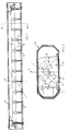
- a luminaire comprises a housing 8 which contains a tubular fluorescent lamp tube 4 set longitudinally and provided with a pair of longitudinal side reflectors 6 to distribute light from the lamp through a light emission aperture or window 2.
- the side reflectors 6 of arcuate downwardly diverging form are positioned opposite each other and parallel to a central plane A (Fig. 2) through the lamp 4, with two end plates 9 and a series of crossblades 10 which extend transversely across the luminaire between the reflectors 6.
- the reflectors 6 are of specular or semi-specular material, concave in section as can be seen in Fig. 2 and are designed to direct light from the lamp 4 through the light emission aperture 2 at suitable angles.
- the side reflectors also prevent a direct view of the lamp above a plane lying at an angle x to plane A, known as the C90 plane in lighting technology terms.
- the crossblades 10 are of specular or semi-specular material, three-dimensional in shape and spaced along plane A to prevent a direct view of the lamp from a position above a plane lying at an angle y (Fig. 1) to a plane B known as the C0 plane in lighting technology terms. Angles x and y are known as cut-off angles.
- the lower edge of each crossblade 10 lies on the plane of the light emission aperture 2.
- the lower edges of the side reflectors 6 may or may not lie on this plane but will be parallel to it.
- Materials used for reflectors have a reflectance of up to approximately 95%, the remainder being absorption losses which cause the material to have some resultant luminance so that the reflector has some luminosity when viewed at angles greater than x and y. Using semi-specular reflecting materials increases the luminosity and this provides better visual comfort for the occupants of the space illuminated.
- the combined profiles of the side reflectors 6, the end plates 9, and the crossblades 10 are such as to reflect light into the space to provide the required light distribution.
- the part of the light emission aperture 2 between the reflectors 6 and each pair of adjacent crossblades 10 is, in lighting technology terms, called a cell. These cells are typically rectangular.
- the efficiency of the reflector system is dependent upon the reflectance of the reflector material, the profiles of the reflecting surfaces, and the number of crossblades in the luminaire. Efficiency is impaired to some extent as a result of the obstruction caused by the crossblades themselves which nevertheless are necessary for the purpose of preventing visibility of the lamp above the cut-off angles.
- the invention seeks to achieve an improvement in illumination efficiency according to the design of the crossblade to minimise obstruction thereby.
- Each crossblade 10 can be made from the same material as the side reflectors 6 and the end plates 9, or from other materials. It has a cross section typically as shown in Fig. 1.
- the profile tapers downwardly and is preferably curved and concave but alternatively may be straight. The profile is determined according to the requirement to direct light from the lamp below the cut-off angle y as shown in Fig. 1.
- the crossblade has two limbs 13 and 14 one on each side of each vertical plane B, and so there is a gap between the two limbs at the upper edge, which is usually open but may be closed to form a common upper edge.
- the upper edge or edges of each limb may be straight and horizontal or may curve about the lamp 4 and be inclined upwardly as shown at 12 in Fig. 2.
- the crossblade has a larger light reflecting surface than is necessary for the strict purpose of screening a direct view of the lamp.
- a line 3 extends from the bottom edge region of each side reflector 6 and is tangential to the underside of the lamp 4. This line defines the angle x, and is equivalent to the cut-off line defining the angle y in Fig. 1.
- Fig. 2 also shows another line C extending from the bottom edge of each side reflector 6 and tangential to the upper surface region of the lamp 4 and defines the angle z.
- These lines (forming planes extending longitudinally along the appliance one on each side of plane A) may be referred to as the screening lines or planes.
- the central area between the screening lines C through plane A is the working area of the crossblade in so far as direct lamp screening is concerned.
- the profiled sections 10a of the crossblades 10 outside of the screening lines C have no affect on direct lamp shielding but are necessary to avoid ladder flash, that is to prevent reflections of the lamp in the side reflectors when looking into the reflector from diagonal directions below angles x and y.
- the crossblades 10 must enclose the space between the side reflectors 6 to form the closed cells.
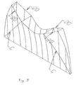
- Fig. 3 it will be seen that the upper edge of the profiled section outside of the screening lines C are reduced in thickness along lines 20 and thus reduce the obstruction caused by the upper edge of the crossblade to light being emitted through the light emission aperture 2.
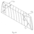
- Fig. 4 shows how the upper region of the crossblade including its upper edge is tapered outwardly from line C, with the result that maximum light obstruction occurs only at the upper end of each line C. Also, in this embodiment, the outer edge of the crossblade is of uniform width.
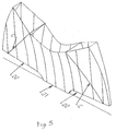
- FIG. 5 a similar crossblade profile is shown save for the lower edge having a central portion 21 lying on the plane of the light emission aperture and side sections 22 which curve upwardly and outwardly towards the outer transverse edges of the blade.
- the lower edge of the crossblade is straight and horizontal and lies on the plane of the light emission aperture.
- the upper edge of the blade is horizontal, but is tapered in its side regions beyond lines C and along tapered upper edge lines 23.
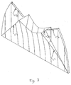
- Fig. 7 in another embodiment, the side walls of the crossblade, beyond lines C are stepped down to a narrow parallel configuration as shown at 24.
- the overall upper edge of the crossblade in the embodiment of Fig. 7 is, however, upwardly curved as in Fig. 3.
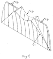
- the central upper edge region 25 is curved about the lamp as in Figs. 2 to 5 and Fig. 7, but outwardly beyond the lines C the upper edge is narrow and defined by a pair of horizontal parallel lines 26.
- the crossblades may be made from sheet metal, usually aluminium, having a specular or semi-specular surface, typically anodised or chemically coated. Alternatively they may be of sheet steel having polished or painted surfaces. Still further, the crossblades may alternatively be made from a plastics material by injection moulding and have reflective outer surfaces created by metal vapour deposition or by other metallising processes, or by the application of a reflective cover material.
- Crossblades embodying the invention display a change of the reflecting surface at and beyond the screening lines C. These edge regions may be light absorbing rather than light reflecting and thus may provide some luminosity.
- the edge regions may be of a different material from the reflecting surface of the region between the screening lines C.
- the edge regions may not necessarily be a plane surface but may be textured in some way, perhaps with prisms, to change the direction of the light reflected from these outer edge regions.
- stepped or prismatic surfaces 27 and 28 are formed in the edge regions beyond lines C.
- each screening line shall extend upwardly to a tangent to the upper side of the nearest lamp or tube.
Abstract
Description
- THIS INVENTION concerns an overhead lighting appliance of the type known as a luminaire and consisting essentially of one or more horizontally disposed lamp tubes housed within a generally arcuately diverging longitudinal reflector assembly with crossblades at spaced disposition along the reflector assembly and extending at right angles to the longitudinal axis of the fluorescent lamp tube.
- The purpose of the crossblades, in addition to assisting reflection of the light outwardly of the appliance, is to remove glare from the appliance by obscuring a direct line of sight to the lamp tube beyond a certain position beneath the appliance.
- Whilst avoiding glare by the provision of such crossblades it is essential also to ensure, as far as possible, that the light output from the lamp tube is not excessively impaired or reduced by the presence of the crossblades between the tube and the light emission aperture or window of the appliance.
- Typically, such crossblades are inwardly curved and tapered downwardly in cross-section, each terminating in a narrow line at its base which extends transversely across the appliance. At its upper end, each crossblade must have a thickness adequate to prevent direct reflection from the lamp tube thus to avoid glare and it is an object of the present invention to provide a crossblade design as a compromise between minimising glare and preventing, as far as possible, any appreciable loss of light output.
- According to the present invention, an overhead lighting appliance having at least one longitudinally extending and horizontally disposed lamp tube housed in an upper region of a reflector assembly of generally arcuate downwardly diverging form, including longitudinally spaced cross blades extending transversely across the reflector housing; characterised in that each cross blade includes opposed outer and upper regions of reduced cross section extending outwardly from respective inclined planes which lie along the appliance and extend upwardly from adjacent outer lowermost corner regions respectively of the cross blade and form tangents to an upper semi-circle concentric with the longitudinal axis of the lamp tube.
- Embodiments of the invention will now be described, by way of example only, with reference to the accompanying drawings, in which:-
- Fig. 1 is a partially cut-away side elevation of a lighting appliance incorporating the invention;
- Fig. 2 is an enlarged cross-section taken on line II-II of Fig. 1;
- Fig. 3 is an enlarged perspective view of a crossblade being part of the appliance;
- Fig. 4 is a perspective view of a modified crossblade, and shows the position of the lamp tube in relation thereto;
- Fig. 5 is a perspective view of a further modified crossblade;
- Fig. 6 is a perspective view of a still further modified crossblade;
- Fig. 7 is a perspective view of a still further modified crossblade;
- Fig. 8 is a perspective view of a still further modified crossblade.
- and Fig. 9 is a perspective view of a still further modified crossblade.
-
- Referring now to the drawings, a luminaire comprises a
housing 8 which contains a tubular fluorescent lamp tube 4 set longitudinally and provided with a pair oflongitudinal side reflectors 6 to distribute light from the lamp through a light emission aperture or window 2. - The
side reflectors 6 of arcuate downwardly diverging form are positioned opposite each other and parallel to a central plane A (Fig. 2) through the lamp 4, with twoend plates 9 and a series ofcrossblades 10 which extend transversely across the luminaire between thereflectors 6. - The
reflectors 6 are of specular or semi-specular material, concave in section as can be seen in Fig. 2 and are designed to direct light from the lamp 4 through the light emission aperture 2 at suitable angles. The side reflectors also prevent a direct view of the lamp above a plane lying at an angle x to plane A, known as the C90 plane in lighting technology terms. - The
crossblades 10 are of specular or semi-specular material, three-dimensional in shape and spaced along plane A to prevent a direct view of the lamp from a position above a plane lying at an angle y (Fig. 1) to a plane B known as the C0 plane in lighting technology terms. Angles x and y are known as cut-off angles. The lower edge of eachcrossblade 10 lies on the plane of the light emission aperture 2. The lower edges of theside reflectors 6 may or may not lie on this plane but will be parallel to it. - Materials used for reflectors have a reflectance of up to approximately 95%, the remainder being absorption losses which cause the material to have some resultant luminance so that the reflector has some luminosity when viewed at angles greater than x and y. Using semi-specular reflecting materials increases the luminosity and this provides better visual comfort for the occupants of the space illuminated.
- The combined profiles of the
side reflectors 6, theend plates 9, and thecrossblades 10 are such as to reflect light into the space to provide the required light distribution. The part of the light emission aperture 2 between thereflectors 6 and each pair ofadjacent crossblades 10 is, in lighting technology terms, called a cell. These cells are typically rectangular. The efficiency of the reflector system is dependent upon the reflectance of the reflector material, the profiles of the reflecting surfaces, and the number of crossblades in the luminaire. Efficiency is impaired to some extent as a result of the obstruction caused by the crossblades themselves which nevertheless are necessary for the purpose of preventing visibility of the lamp above the cut-off angles. - The invention seeks to achieve an improvement in illumination efficiency according to the design of the crossblade to minimise obstruction thereby.
- Each
crossblade 10 can be made from the same material as theside reflectors 6 and theend plates 9, or from other materials. It has a cross section typically as shown in Fig. 1. The profile tapers downwardly and is preferably curved and concave but alternatively may be straight. The profile is determined according to the requirement to direct light from the lamp below the cut-off angle y as shown in Fig. 1. - In construction, the crossblade has two
limbs - Where the upper edge profile extends upwardly, this is to avoid a bright array of reflections in the
side reflectors 6 known as ladder flash. These reflections are caused by reflection of the self-lit interior of the crossblades reflecting at angles close to the cut-off angle x and occur just above each crossblade. Ladder flash is undesirable from a visual point of view. - However, such a profile results in an excessive obstruction to light output. The space inside the crossblade or between the two profiled limbs, if open, accepts light which is thus wasted. The deeper (taller) the outer parts of the crossblade, the greater the space between the two diverging limbs and so the greater is the waste of light. Where the upper edge of the crossblade is inclined upwardly as in Fig. 2 then the space between the two limbs becomes excessive towards the
side reflectors 6. Thus the solution to eliminate ladder flash has the disadvantage of increasing the obstruction which the crossblade imposes on the light leaving the lamp through the light emission aperture. - The crossblade has a larger light reflecting surface than is necessary for the strict purpose of screening a direct view of the lamp. As shown in Fig. 2, a
line 3 extends from the bottom edge region of eachside reflector 6 and is tangential to the underside of the lamp 4. This line defines the angle x, and is equivalent to the cut-off line defining the angle y in Fig. 1. - Fig. 2 also shows another line C extending from the bottom edge of each
side reflector 6 and tangential to the upper surface region of the lamp 4 and defines the angle z. These lines (forming planes extending longitudinally along the appliance one on each side of plane A) may be referred to as the screening lines or planes. - The central area between the screening lines C through plane A is the working area of the crossblade in so far as direct lamp screening is concerned. The
profiled sections 10a of thecrossblades 10 outside of the screening lines C have no affect on direct lamp shielding but are necessary to avoid ladder flash, that is to prevent reflections of the lamp in the side reflectors when looking into the reflector from diagonal directions below angles x and y. Thecrossblades 10 must enclose the space between theside reflectors 6 to form the closed cells. - Referring now to Fig. 3 it will be seen that the upper edge of the profiled section outside of the screening lines C are reduced in thickness along
lines 20 and thus reduce the obstruction caused by the upper edge of the crossblade to light being emitted through the light emission aperture 2. - Fig. 4 shows how the upper region of the crossblade including its upper edge is tapered outwardly from line C, with the result that maximum light obstruction occurs only at the upper end of each line C. Also, in this embodiment, the outer edge of the crossblade is of uniform width.
- Referring now to Fig. 5, a similar crossblade profile is shown save for the lower edge having a central portion 21 lying on the plane of the light emission aperture and
side sections 22 which curve upwardly and outwardly towards the outer transverse edges of the blade. - Referring now to Fig. 6 in another embodiment, the lower edge of the crossblade is straight and horizontal and lies on the plane of the light emission aperture. Also, the upper edge of the blade is horizontal, but is tapered in its side regions beyond lines C and along tapered upper edge lines 23.
- Referring now to Fig. 7, in another embodiment, the side walls of the crossblade, beyond lines C are stepped down to a narrow parallel configuration as shown at 24. The overall upper edge of the crossblade in the embodiment of Fig. 7 is, however, upwardly curved as in Fig. 3.
- In a further alternative embodiment as shown in Fig. 8, the central
upper edge region 25 is curved about the lamp as in Figs. 2 to 5 and Fig. 7, but outwardly beyond the lines C the upper edge is narrow and defined by a pair of horizontalparallel lines 26. - In all of the embodiments illustrated the side extensions of the crossblade beyond the lines C serve to prevent ladder flash but are reduced or tapered or reduced in thickness thus to minimise obstruction to light output in those regions.
- While in Figs. 7 and 8 the outer regions are stepped down to a minimum thickness, in the remaining figures the opposed walls of the crossblade are, in effect, bent inwardly about the lines C since the
tapered lines 20, 23 in these embodiments are projected as converging walls outside lines C and extending down from the upper edge of the crossblade to its bottom corners. - The crossblades may be made from sheet metal, usually aluminium, having a specular or semi-specular surface, typically anodised or chemically coated. Alternatively they may be of sheet steel having polished or painted surfaces. Still further, the crossblades may alternatively be made from a plastics material by injection moulding and have reflective outer surfaces created by metal vapour deposition or by other metallising processes, or by the application of a reflective cover material.
- Crossblades embodying the invention display a change of the reflecting surface at and beyond the screening lines C. These edge regions may be light absorbing rather than light reflecting and thus may provide some luminosity.
- The edge regions may be of a different material from the reflecting surface of the region between the screening lines C.
- The edge regions may not necessarily be a plane surface but may be textured in some way, perhaps with prisms, to change the direction of the light reflected from these outer edge regions. Such an embodiment is shown in Fig. 9 wherein stepped or
prismatic surfaces - It is not intended to limit the invention to the above examples, many variations being possible without departing from the scope of the invention which is intended to combine complete screening with optimal light obstruction by reducing the thickness of each crossblade beyond the lines C which extend from respective outer lower edge regions to positions wherein they form tangents to the upper side region of the lamp tube in the assembled luminaire. Where two or more lamp tubes are provided side-by-side between a pair of side reflectors, each screening line shall extend upwardly to a tangent to the upper side of the nearest lamp or tube.
Claims (15)
- An overhead lighting appliance having at least one longitudinally extending and horizontally disposed lamp tube housed in an upper region of a reflector assembly of generally arcuate downwardly diverging form, including longitudinally spaced cross blades extending transversely across the reflector housing; characterised in that each cross blade includes opposed outer and upper regions of reduced cross section extending outwardly from respective inclined planes which lie along the appliance and extend upwardly from adjacent outer lowermost corner regions respectively of the cross blade and form tangents to an upper semi-circle concentric with the longitudinal axis of the lamp tube.
- A lighting appliance according to Claim 1, wherein the inclined planes extend upwardly from the lower edge regions respectively of a pair of opposed side reflectors forming the downwardly diverging reflector assembly.
- A lighting appliance according to Claim 1, wherein the inclined plane extends upwardly from the lowermost outer comers respectively of the cross blades.
- A lighting appliance according to Claim 1, wherein the inclined planes extend upwardly to form tangents to an upper region of the lamp tube.
- A lighting appliance according to Claim 1, wherein the reflector assembly comprises a pair of opposed downwardly diverging concave side reflectors terminating at or the region of their lowermost edges on the plane of the light emission aperture or window of the appliance.
- A lighting appliance according to any preceding claim, in which at least a part of the lowermost edge of each cross blade lies on the plane of the light emission aperture or window of the appliance.
- A lighting appliance according to any preceding claim, wherein the upper edge of each cross blade is straight thus to lie horizontally beneath the lamp tube.
- A lighting appliance according to any one of Claims 1 to 6, wherein the upper edge of each cross blade is curved about the longitudinal axis of the lamp tube and is inclined upwardly on each side thereon.
- A lighting appliance according to any preceding claim, wherein the upper edge of each cross blade is tapered outwardly from said inclined plane.
- A lighting appliance according to any preceding claim, wherein each outer edge of each cross blade is of uniform width.
- A lighting appliance according to any preceding claim, wherein the lower edge of each cross blade has a central portion thereof lying on the plane of the light emission aperture of the appliance and is curved upwardly and outwardly from the central portion towards the outer transverse edges of the cross blade.
- A lighting appliance according to any one of Claims 1 to 8, wherein the walls of the cross blade at and outwardly from said inclined plane are stepped down to a narrower configuration of uniform thickness.
- A lighting appliance according to any preceding claim wherein the surface of each cross blade outwardly of said inclined plane is of a material having different reflective properties from those of the remainder of the blade.
- A lighting appliance according to any preceding claim, wherein the surface of each cross blade outwardly of said inclined plane is of textured or angular formation.
- A lighting appliance according to any preceding claim, wherein the surface of each cross blade outwardly of said inclined plane is of a translucent material.
Applications Claiming Priority (2)
| Application Number | Priority Date | Filing Date | Title |
|---|---|---|---|
| GBGB9908728.0A GB9908728D0 (en) | 1999-04-17 | 1999-04-17 | A lighting appliance |
| GB9908728 | 1999-04-17 |
Publications (2)
| Publication Number | Publication Date |
|---|---|
| EP1094272A2 true EP1094272A2 (en) | 2001-04-25 |
| EP1094272A3 EP1094272A3 (en) | 2002-09-25 |
Family
ID=10851663
Family Applications (1)
| Application Number | Title | Priority Date | Filing Date |
|---|---|---|---|
| EP00303236A Withdrawn EP1094272A3 (en) | 1999-04-17 | 2000-04-17 | A lighting appliance |
Country Status (3)
| Country | Link |
|---|---|
| US (1) | US6443598B1 (en) |
| EP (1) | EP1094272A3 (en) |
| GB (1) | GB9908728D0 (en) |
Cited By (3)
| Publication number | Priority date | Publication date | Assignee | Title |
|---|---|---|---|---|
| WO2006051473A1 (en) * | 2004-11-12 | 2006-05-18 | Koninklijke Philips Electronics N.V. | Luminaire and lamellae louver therefor |
| EP2236915A1 (en) * | 2009-03-31 | 2010-10-06 | Flowil International Lighting (HOLDING) B.V. | Ceiling Light Housing and Lighting Lamellae |
| WO2023061926A1 (en) * | 2021-10-12 | 2023-04-20 | Signify Holding B.V. | A light emitting device |
Families Citing this family (28)
| Publication number | Priority date | Publication date | Assignee | Title |
|---|---|---|---|---|
| ITFI20020077U1 (en) * | 2002-07-19 | 2004-01-19 | Targetti Sankey Spa | ANTI-GLARE GRID FOR TUBULAR LIGHT SOURCES |
| US20060176701A1 (en) * | 2005-02-04 | 2006-08-10 | Shemit Sylvan R | Reflector-baffle for luminaires |
| US7455431B2 (en) | 2005-03-11 | 2008-11-25 | Richard Brower | High efficiency light fixture |
| US10883702B2 (en) | 2010-08-31 | 2021-01-05 | Ideal Industries Lighting Llc | Troffer-style fixture |
| US9822951B2 (en) | 2010-12-06 | 2017-11-21 | Cree, Inc. | LED retrofit lens for fluorescent tube |
| US10309627B2 (en) | 2012-11-08 | 2019-06-04 | Cree, Inc. | Light fixture retrofit kit with integrated light bar |
| US9581312B2 (en) | 2010-12-06 | 2017-02-28 | Cree, Inc. | LED light fixtures having elongated prismatic lenses |
| US9494293B2 (en) | 2010-12-06 | 2016-11-15 | Cree, Inc. | Troffer-style optical assembly |
| US10823347B2 (en) | 2011-07-24 | 2020-11-03 | Ideal Industries Lighting Llc | Modular indirect suspended/ceiling mount fixture |
| US9423117B2 (en) | 2011-12-30 | 2016-08-23 | Cree, Inc. | LED fixture with heat pipe |
| US10544925B2 (en) | 2012-01-06 | 2020-01-28 | Ideal Industries Lighting Llc | Mounting system for retrofit light installation into existing light fixtures |
| US9777897B2 (en) | 2012-02-07 | 2017-10-03 | Cree, Inc. | Multiple panel troffer-style fixture |
| US8905575B2 (en) | 2012-02-09 | 2014-12-09 | Cree, Inc. | Troffer-style lighting fixture with specular reflector |
| US9494294B2 (en) | 2012-03-23 | 2016-11-15 | Cree, Inc. | Modular indirect troffer |
| US9310038B2 (en) | 2012-03-23 | 2016-04-12 | Cree, Inc. | LED fixture with integrated driver circuitry |
| US10054274B2 (en) | 2012-03-23 | 2018-08-21 | Cree, Inc. | Direct attach ceiling-mounted solid state downlights |
| US9360185B2 (en) | 2012-04-09 | 2016-06-07 | Cree, Inc. | Variable beam angle directional lighting fixture assembly |
| US9874322B2 (en) | 2012-04-10 | 2018-01-23 | Cree, Inc. | Lensed troffer-style light fixture |
| US9285099B2 (en) * | 2012-04-23 | 2016-03-15 | Cree, Inc. | Parabolic troffer-style light fixture |
| US8931929B2 (en) | 2012-07-09 | 2015-01-13 | Cree, Inc. | Light emitting diode primary optic for beam shaping |
| US9494304B2 (en) | 2012-11-08 | 2016-11-15 | Cree, Inc. | Recessed light fixture retrofit kit |
| US10648643B2 (en) | 2013-03-14 | 2020-05-12 | Ideal Industries Lighting Llc | Door frame troffer |
| US9052075B2 (en) | 2013-03-15 | 2015-06-09 | Cree, Inc. | Standardized troffer fixture |
| USD786471S1 (en) | 2013-09-06 | 2017-05-09 | Cree, Inc. | Troffer-style light fixture |
| USD807556S1 (en) | 2014-02-02 | 2018-01-09 | Cree Hong Kong Limited | Troffer-style fixture |
| USD772465S1 (en) | 2014-02-02 | 2016-11-22 | Cree Hong Kong Limited | Troffer-style fixture |
| US10451253B2 (en) | 2014-02-02 | 2019-10-22 | Ideal Industries Lighting Llc | Troffer-style fixture with LED strips |
| US20190346089A1 (en) * | 2018-05-08 | 2019-11-14 | Elite Lighting | Light Fixture |
Family Cites Families (5)
| Publication number | Priority date | Publication date | Assignee | Title |
|---|---|---|---|---|
| AT381577B (en) * | 1983-04-08 | 1986-11-10 | Bartenbach Christian | GLARE-FREE LAMP FOR A ROD-SHAPED LIGHT SOURCE |
| DE3406447C2 (en) * | 1984-02-22 | 1995-03-16 | Christian Bartenbach | Shielding for a lamp with a rod-shaped lamp |
| US4751626A (en) * | 1987-05-28 | 1988-06-14 | Columbia Lighting, Inc. | Reflector system for a luminaire |
| NZ300261A (en) * | 1995-02-14 | 1997-11-24 | Philips Electronics Nv | Luminaire with lamellae having concave outer edges for providing more uniform illumination |
| FR2738623A1 (en) * | 1995-09-13 | 1997-03-14 | Philips Eclairage | Fluorescent light fitting with improved louvred cover |
-
1999
- 1999-04-17 GB GBGB9908728.0A patent/GB9908728D0/en not_active Ceased
-
2000
- 2000-04-14 US US09/550,323 patent/US6443598B1/en not_active Expired - Fee Related
- 2000-04-17 EP EP00303236A patent/EP1094272A3/en not_active Withdrawn
Non-Patent Citations (1)
| Title |
|---|
| None |
Cited By (3)
| Publication number | Priority date | Publication date | Assignee | Title |
|---|---|---|---|---|
| WO2006051473A1 (en) * | 2004-11-12 | 2006-05-18 | Koninklijke Philips Electronics N.V. | Luminaire and lamellae louver therefor |
| EP2236915A1 (en) * | 2009-03-31 | 2010-10-06 | Flowil International Lighting (HOLDING) B.V. | Ceiling Light Housing and Lighting Lamellae |
| WO2023061926A1 (en) * | 2021-10-12 | 2023-04-20 | Signify Holding B.V. | A light emitting device |
Also Published As
| Publication number | Publication date |
|---|---|
| GB9908728D0 (en) | 1999-06-09 |
| US6443598B1 (en) | 2002-09-03 |
| EP1094272A3 (en) | 2002-09-25 |
Similar Documents
| Publication | Publication Date | Title |
|---|---|---|
| US6443598B1 (en) | Lighting appliance with glare reducing cross blades | |
| US5758954A (en) | Luminaire | |
| US7828468B2 (en) | Louver assembly for a light fixture | |
| US4729075A (en) | Constant zone reflector for luminaires and method | |
| CA2180712C (en) | Lighting fixture having a parabolic louver | |
| US7108398B2 (en) | Luminaire and lamellae grid | |
| EP1606552B1 (en) | Luminaire | |
| US6764199B2 (en) | Light distributor, lighting device comprising at least one light distributor and method for the production of a light distributor | |
| EP1151227B1 (en) | Luminaire without lamellae | |
| EP0959295B1 (en) | Luminaire | |
| EP1994331B1 (en) | Luminaire and lamellae louver | |
| US8118453B2 (en) | Luminaire and lamellae louver therefor | |
| US20070223229A1 (en) | Luminaire and Lamellae Louver Therefor | |
| CA2310474A1 (en) | Luminaire | |
| EP1376008A2 (en) | Lighting device | |
| JP4353896B2 (en) | Lighting apparatus and lamellar louver therefor | |
| EP3354981A1 (en) | A component of an optical system of an anti-glare lighting fixture | |
| GB2300470A (en) | A reflector unit for a light fitting | |
| MXPA00004687A (en) | Luminaire | |
| JPH03226906A (en) | Lighting equipment | |
| PL157304B1 (en) | Lighting fitting for gas-filled discharge lamps in particular those for use as daylight substitute in greenhouses |
Legal Events
| Date | Code | Title | Description |
|---|---|---|---|
| PUAI | Public reference made under article 153(3) epc to a published international application that has entered the european phase |
Free format text: ORIGINAL CODE: 0009012 |
|
| AK | Designated contracting states |
Kind code of ref document: A2 Designated state(s): AT BE CH CY DE DK ES FI FR GB GR IE IT LI LU MC NL PT SE |
|
| AX | Request for extension of the european patent |
Free format text: AL;LT;LV;MK;RO;SI |
|
| PUAL | Search report despatched |
Free format text: ORIGINAL CODE: 0009013 |
|
| AK | Designated contracting states |
Kind code of ref document: A3 Designated state(s): AT BE CH CY DE DK ES FI FR GB GR IE IT LI LU MC NL PT SE |
|
| AX | Request for extension of the european patent |
Free format text: AL;LT;LV;MK;RO;SI |
|
| AKX | Designation fees paid | ||
| REG | Reference to a national code |
Ref country code: DE Ref legal event code: 8566 |
|
| STAA | Information on the status of an ep patent application or granted ep patent |
Free format text: STATUS: THE APPLICATION IS DEEMED TO BE WITHDRAWN |
|
| 18D | Application deemed to be withdrawn |
Effective date: 20030326 |