EP0959294B1 - Indirect wide beam luminaire - Google Patents
Indirect wide beam luminaire Download PDFInfo
- Publication number
- EP0959294B1 EP0959294B1 EP99107617A EP99107617A EP0959294B1 EP 0959294 B1 EP0959294 B1 EP 0959294B1 EP 99107617 A EP99107617 A EP 99107617A EP 99107617 A EP99107617 A EP 99107617A EP 0959294 B1 EP0959294 B1 EP 0959294B1
- Authority
- EP
- European Patent Office
- Prior art keywords
- reflector
- centre plane
- section
- centre
- housing
- Prior art date
- Legal status (The legal status is an assumption and is not a legal conclusion. Google has not performed a legal analysis and makes no representation as to the accuracy of the status listed.)
- Expired - Lifetime
Links
Images


Classifications
-
- F—MECHANICAL ENGINEERING; LIGHTING; HEATING; WEAPONS; BLASTING
- F21—LIGHTING
- F21S—NON-PORTABLE LIGHTING DEVICES; SYSTEMS THEREOF; VEHICLE LIGHTING DEVICES SPECIALLY ADAPTED FOR VEHICLE EXTERIORS
- F21S6/00—Lighting devices intended to be free-standing
- F21S6/005—Lighting devices intended to be free-standing with a lamp housing maintained at a distance from the floor or ground via a support, e.g. standing lamp for ambient lighting
-
- F—MECHANICAL ENGINEERING; LIGHTING; HEATING; WEAPONS; BLASTING
- F21—LIGHTING
- F21V—FUNCTIONAL FEATURES OR DETAILS OF LIGHTING DEVICES OR SYSTEMS THEREOF; STRUCTURAL COMBINATIONS OF LIGHTING DEVICES WITH OTHER ARTICLES, NOT OTHERWISE PROVIDED FOR
- F21V7/00—Reflectors for light sources
- F21V7/0008—Reflectors for light sources providing for indirect lighting
-
- F—MECHANICAL ENGINEERING; LIGHTING; HEATING; WEAPONS; BLASTING
- F21—LIGHTING
- F21S—NON-PORTABLE LIGHTING DEVICES; SYSTEMS THEREOF; VEHICLE LIGHTING DEVICES SPECIALLY ADAPTED FOR VEHICLE EXTERIORS
- F21S6/00—Lighting devices intended to be free-standing
Definitions
- the invention relates to a wide-beam indirect light according to the preamble of claim 1.
- the invention is therefore a luminaire of the type mentioned to be improved so that even with fluorescent tubes with a smaller diameter, a good and uniform illumination of the room while avoiding excessive luminance on the ceiling can be achieved directly above the lamp.
- the relatively flat light housing 14 by means of a short lamp shaft 16 and an approximately conical ceiling rosette 18 is mounted at a short distance from the ceiling 10.
- the luminaire housing 14 is slightly convexly curved downwards and is made of translucent material, however, e.g. in the form of perforated metal sheet, mesh fabric, grid mesh, frosted glass or by means of other perforated material optionally more or less light can pass down.
- At the side edges of the lamp housing 14 ends the same in each case bent-over portions 22. Upward, the lamp housing 14 is open.
- the luminaire housing 14 is formed symmetrically to a vertical center plane 26 extending in the direction of the longitudinal extent of the luminaire housing 14. At equal distances from the median plane 26 and at the same height above the housing 14, ie, approximately at the height of the bent portions 22 of the lamp housing 14, one is parallel to the median plane 26 extending arc tube 28 is arranged.
- each arc tube 28 there is arranged a high-gloss reflector consisting of perforated sheet, which is designated generally by 30.
- a first approximately vertical portion 32 abuts against the middle plane 26 facing side of the associated arc tube 28 and protrudes slightly above the same.
- a second approximately horizontal portion 34 of the reflector 30 whose length corresponds approximately to the diameter of the arc tube 28.
- the second portion 34 then passes into a third, away from the median plane 26 upwardly inclined longer portion 36, which is slightly convex upward and convex slightly curved downwards. In the illustrated embodiment, it has an average slope of about 45 °.
- the length of the third section 36 is a multiple of the first section 32 and the second section 34, respectively.
- center reflector 38 In the area between the two reflectors 30 and the two fluorescent tubes 28 a symmetrical to the median plane 26 arranged center reflector 38 is provided on both sides of the median plane 26 each have an upper, upwardly to the median plane 26 inclined planar reflector surface 40 and one lower, according to Having downwardly inclined to the center plane, substantially flat reflector surface 42.
- the center reflector 38 further includes a respective downwardly from the center plane 26 inclined away, in each case below one of the light tubes 28 arranged sub-reflector 44, which is connected to it in one piece or otherwise rigidly connected.
- a parallel to the median plane 26 extending over the length of the entire luminaire opening 48 is provided, which at best by not shown, thin Haltstege or the like may be interrupted.
- the entire center reflector 38 including the sub-reflector 44 is preferably made of closed high-gloss material.
- the lower edge 50 of the first vertical section 32 of each reflector 30 preferably abuts the upper side of the associated lower reflector 44.
- lateral portions D of the lamp housing 14 is in each case at a distance approximately parallel to these ever a side reflector 52 is attached. It extends approximately from the bent portions 22 of the housing 14 to its inner edge 54 at a short distance below the associated arc tube 28 and above the associated sub-reflector 44 and is substantially flat except for the outer edge regions. It is preferably also made of closed high-gloss material and is slightly inclined down to the center plane, so that between the side reflector 52 and the third portion 36 of the associated reflector 30 is an upwardly opening, unobstructed by reflectors beam angle B for the light of the associated arc tube 28th is formed.
- the Abstrahlwinkel Society B has obliquely laterally upward, whereby glare in the direction of arrow G from obliquely downwards are avoided, however, a good and uniform illumination of the space is achieved laterally and upwards.
- the third curved portion 36 of the perforated plate reflector 30 determines the size of the radiation angle B.
- the direct radiation from the arc tube 28 down toward the housing 14 is prevented by the side reflector 52 and the sub-reflector 44.
- the side reflector 52 in each case supports the wide-angle characteristic of the luminaire, which is essentially determined by the angle B.
- a translucent horizontal cover plate 56 is attached, which provides some protection against contamination of the central reflector 38 and the tubes 28.
- the described shape of the three sections of the two perforated plate reflectors 30 serves for a certain, but not complete shading of the fluorescent tubes 28 in the direction of the ceiling 10 above the reflectors 30.
- the result is a perforated plate of these reflectors 30, a radiation area determined by the angle C immediately after up against the ceiling 10.
- the gap between the inner edge 54 of the side reflector 52 and the upper side of the lower reflector 44 each directly light from the arc tube 28 in an angular range D 'irradiated to the lateral portions D of the housing 14th lighten.
- Light emitted by the first sections 32 of the perforated plate reflectors 30 is reflected via the lower reflection surfaces 42 of the center reflector 38 through the opening 48 of the same downward in an angular range E 'on the central portion E of the housing 14, while directly through the openings 48 of the Luminous tubes 28 radiated light in angular ranges E '' on the middle section E incident.
- the angle of incidence is so shallow that no direct light would penetrate through holes of a perforated sheet material of the housing 14 to the outside.
- a largely uniform lightening of the housing 14 is achieved.
- a transparent film could advantageously be placed on the inside of the housing 14.
- the lamp shown in Figure 1 is shown in its short suspension on the ceiling 10 in approximately proportion to the room height, while shown in Figure 4 in their arrangement on a standing on the floor 58 tall stand 60 with stand 62 is.
Abstract
Description
Die Erfindung betrifft eine breitstrahlende Indirektleuchte nach dem oberbegriff des Anspruchs 1.The invention relates to a wide-beam indirect light according to the preamble of
Aus DE 195 37 685 C1 ist eine derartige Indirektleuchte bekannt, durch deren Ausgestaltung das Problem gelöst ist, daß trotz eines kleinen Abstands zwischen Raumdecke und Unterkante der Leuchte eine zu hohe Leuchtdichte an der Decke unmittelbar oberhalb der Leuchte vermieden wird, andererseits der größere Teil des abgestrahlten Lichtes seitlich und schräg nach oben abgestrahlt wird, um eine gute und gleichmäßige Ausleuchtung des Raumes zu erzielen.From DE 195 37 685 C1, such an indirect light is known, by the design of the problem is solved, that despite a small distance between the ceiling and lower edge of the lamp too high a luminance on the ceiling immediately above the lamp is avoided, on the other hand, the greater part of radiated light laterally and obliquely upwards to achieve a good and uniform illumination of the room.
Während diese bekannte Indirektleuchte für Leuchtröhren mit einem Durchmesser von 26 mm und entsprechender Leuchtdichte das geschilderte Problem ausgezeichnet löst, wird das Problem durch die Verwendung von Leuchtröhren mit 16 mm Durchmesser so verschärft, daß die bekannte Leuchte nicht mehr in allen Fällen ausreicht.While this well-known indirect light bulb for lighting tubes with a diameter of 26 mm and corresponding luminance solves the problem described excellent, the problem is exacerbated by the use of fluorescent tubes with 16 mm diameter so that the known light is no longer sufficient in all cases.
Durch die Erfindung soll daher eine Leuchte der eingangs genannten Art so verbessert werden, daß auch bei Leuchtröhren mit kleinerem Durchmesser eine gute und gleichmäßige Ausleuchtung des Raumes bei Vermeidung einer zu starken Leuchtdichte an der Decke unmittelbar oberhalb der Leuchte erzielt werden kann.The invention is therefore a luminaire of the type mentioned to be improved so that even with fluorescent tubes with a smaller diameter, a good and uniform illumination of the room while avoiding excessive luminance on the ceiling can be achieved directly above the lamp.
Diese Aufgabe wird erfindungsgemäß durch die Merkmale des Anspruchs 1 gelöst.This object is achieved by the features of
Durch die Verwendung von Reflektoren aus Lochblech seitlich und oberhalb der Leuchtröhren wird einerseits eine ausreichende Aufhellung der Decke oberhalb der Leuchte erreicht, andererseits eine zu starke Leuchtdichte in diesem nahe der Leuchte gelegenen Bereich der Decke vermieden. Andererseits wird der größere Teil der Lichtabstrahlung in einem großen Winkelbereich seitlich nach oben abgelenkt, ohne daß eine Blendung in einer seitlich etwas nach unten weisenden Richtung hervorgerufen wird.By using reflectors made of perforated plate laterally and above the fluorescent tubes on the one hand sufficient lightening of the ceiling above the lamp is achieved, on the other hand avoided excessive luminance in this located near the lamp area of the ceiling. On the other hand, the greater part of the light emission is deflected laterally upward in a large angular range, without causing glare in a laterally slightly downward direction.
In den Unteransprüchen sind vorteilhafte Ausgestaltungen der Erfindung unter Schutz gestellt. Die Anordnung von Lochblechteilen im Gehäuse zusammen mit weiteren Reflektoren im mittleren, seitlichen und unteren Bereich des Innenraums des Leuchtengehäuses kann wahlweise für eine noch gleichmäßigere Lichtverteilung und Vermeidung von Schattenbildungen und insbesondere für eine gleichmäßige Aufhellung des Gehäuses nach unten sorgen.In the subclaims advantageous embodiments of the invention are put under protection. The arrangement of perforated sheet metal parts in the housing together with other reflectors in the middle, side and bottom of the interior of the lamp housing can optionally provide even more even light distribution and avoid shadowing and in particular for a uniform lightening of the housing down.
Anhand der Figuren werden bevorzugte Ausführungsbeispiele der Erfindung näher erläutert. Es zeigt:
Figur 1- einen schematischen Schnitt senkrecht zur Längserstreckung der an einer Raumdecke kurz abgehängten Indirektleuchte gemäß der Erfindung,
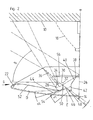
- Figur 2
- eine vergrößerte Darstellung der linken Hälfte der Fig. 1,
- Figur 3
- eine verkleinerte Darstellung der Leuchte gemäß Fig. 1, und
- Figur 4
- die auf einem hohen Ständer nahe der Raumdecke angebrachte Leuchte gemäß Fig.1 ohne die der Aufhängung dienenden Teile.
- FIG. 1
- a schematic section perpendicular to the longitudinal extent the indirectly suspended on a ceiling ceiling indirect light according to the invention,
- FIG. 2
- an enlarged view of the left half of Fig. 1,
- FIG. 3
- a reduced view of the lamp of FIG. 1, and
- FIG. 4
- the mounted on a high stand near the ceiling lamp according to Figure 1 without the suspension serving parts.
Da der Abstand A von der Raumdecke 10 zur Unterkante 12 des Leuchtengehäuses 14 gemäß Fig.1 möglichst klein sein soll, ist das verhältnismäßig flache Leuchtengehäuse 14 mittels eines kurzen Leuchtenschaftes 16 und einer etwa kegelförmigen Deckenrosette 18 in kurzem Abstand von der Decke 10 befestigt. Das Leuchtengehäuse 14 ist nach unten leicht konvex gekrümmt und besteht aus lichtdurchlässigem Material, das jedoch z.B. in Form von Lochblech, Gittergewebe, Gittergeflecht, Milchglas oder mittels anderen perforierten Materials wahlweise mehr oder weniger Licht nach unten durchlassen kann. An den Seitenkanten des Leuchtengehäuses 14 endet dasselbe jeweils in oben umgebogenen Abschnitten 22. Nach oben ist das Leuchtengehäuse 14 offen.Since the distance A from the
Das Leuchtengehäuse 14 ist symmetrisch zu einer in Richtung der Längserstreckung des Leuchtengehäuses 14 verlaufenden vertikalen Mittelebene 26 ausgebildet. In gleichen Abständen von der Mittelebene 26 sowie in gleicher Höhe oberhalb des Gehäuses 14, d.h. etwa in der Höhe der umgebogenen Abschnitte 22 des Leuchtengehäuses 14, ist je eine parallel zur Mittelebene 26 verlaufende Leuchtröhre 28 angeordnet.The
Nahe jeder Leuchtröhre 28 ist ein aus Lochblech bestehender Hochglanz-Reflektor angeordnet, der allgemein mit 30 bezeichnet ist. Ein erster etwa vertikaler Abschnitt 32 liegt an der der Mittelebene 26 zugewandten Seite der zugehörigen Leuchtröhre 28 an und ragt etwas über dieselbe nach oben. In geringem Abstand von der Oberseite der Leuchtröhre 28 schließt sich an den ersten Abschnitt 32 ein zweiter etwa horizontaler Abschnitt 34 des Reflektors 30 an, dessen Länge annähernd dem Durchmesser der Leuchtröhre 28 entspricht. Der zweite Abschnitt 34 geht sodann in einen dritten, von der Mittelebene 26 weg nach oben geneigten längeren Abschnitt 36 über, der nach oben leicht konvex und nach unten leicht konkav gewölbt ist. Bei der dargestellten Ausführungsform besitzt er eine mittlere Steigung von etwa 45°. Im vertikalen Schnitt der Fig.1 beträgt die Länge des dritten Abschnitts 36 das Mehrfache des ersten Abschnitts 32 bzw. des zweiten Abschnitts 34.Near each
Im Bereich zwischen den beiden Reflektoren 30 und den beiden Leuchtröhren 28 ist ein symmetrisch zur Mittelebene 26 angeordneter Mittelreflektor 38 vorgesehen, der zu beiden Seiten der Mittelebene 26 je eine obere, nach oben zur Mittelebene 26 hin geneigte ebene Reflektorfläche 40 und je eine untere, nach unten zur Mittelebene hin geneigte, im wesentlichen ebene Reflektorfläche 42 aufweist. Der Mittelreflektor 38 weist ferner je einen nach unten von der Mittelebene 26 weg geneigten, jeweils unterhalb einer der Leuchtröhren 28 angeordneten Unterreflektor 44 auf, der mit ihm einstückig oder auf sonstige Weise starr verbunden ist. Jeweils zwischen der unteren ebenen Reflektorfläche 42 und dem oberen Rand 46 des Unterreflektors 44 ist ein parallel zur Mittelebene 26 über die Länge der gesamten Leuchte verlaufender Durchbruch 48 vorgesehen, der allenfalls durch nicht dargestellte, dünne Haltestege oder dergleichen unterbrochen sein kann. Der gesamte Mittelreflektor 38 einschließlich des Unterreflektors 44 besteht vorzugsweise aus geschlossenem Hochglanzmaterial. Der untere Rand 50 des ersten vertikalen Abschnitts 32 jedes Reflektors 30 liegt vorzugsweise an der Oberseite des zugehörigen Unterreflektors 44 an.In the area between the two
Oberhalb der von der Mittelebene 26 abgelegenen seitlichen Abschnitte D des Leuchtengehäuses 14 ist jeweils im Abstand etwa parallel zu diesen je ein Seitenreflektor 52 angebracht. Er verläuft etwa von den umgebogenen Abschnitten 22 des Gehäuses 14 bis zu seinem inneren Rand 54 jeweils in geringem Abstand unterhalb der zugehörigen Leuchtröhre 28 und oberhalb des zugehörigen Unterreflektors 44 und ist bis auf die äußeren Randbereiche im wesentlichen eben. Er besteht vorzugsweise ebenfalls aus geschlossenem Hochglanzmaterial und ist zur Mittelebene hin nach unten leicht geneigt, so daß zwischen dem Seitenreflektor 52 und dem dritten Abschnitt 36 des zugehörigen Reflektors 30 ein sich nach oben öffnender, von Reflektoren unbehinderter Abstrahlwinkel B für das Licht der zugehörigen Leuchtröhre 28 gebildet wird. Der Abstrahlwinkelbereich B weist schräg seitlich nach oben, wodurch Blendungen in Blickrichtung des Pfeils G von schräg unten sicher vermieden werden, jedoch eine gute und gleichmäßige Ausleuchtung des Raumes seitlich und nach oben erreicht wird. Der dritte gewölbte Abschnitt 36 des Lochblechreflektors 30 ist bestimmend für die Größe des Abstrahlwinkels B. Die direkte Abstrahlung von der Leuchtröhre 28 nach unten in Richtung des Gehäuses 14 wird durch den Seitenreflektor 52 und den Unterreflektor 44 verhindert. Gleichzeitig unterstützt der Seitenreflektor 52 jeweils die breitstrahlende Charakteristik der Leuchte, die im wesentlichen durch den Winkel B bestimmt wird.Above the remote from the
Über dem Mittelreflektor 38 und den Leuchtröhren 28 ist eine lichtdurchlässige horizontale Abdeckplatte 56 angebracht, die einen gewissen Schutz gegen Verschmutzung des Mittelreflektors 38 und der Leuchtröhren 28 bietet.Above the
Die geschilderte Form der drei Abschnitte der beiden Lochblechreflektoren 30 dient zu einer gewissen, jedoch nicht vollständigen Abschattung der Leuchtröhren 28 in Richtung Decke 10 oberhalb der Reflektoren 30. Es ergibt sich dabei durch das Lochblech dieser Reflektoren 30 ein durch den Winkel C bestimmter Abstrahlbereich unmittelbar nach oben gegen die Decke 10.The described shape of the three sections of the two perforated
Um auch das Leuchtengehäuse 14 selbst möglichst gleichmäßig aufzuhellen, wird durch den Spalt zwischen dem inneren Rand 54 des Seitenreflektors 52 und der Oberseite des Unterreflektors 44 jeweils direkt Licht von der Leuchtröhre 28 in einen Winkelbereich D' eingestrahlt, um die seitlichen Abschnitte D des Gehäuses 14 aufzuhellen. Durch die ersten Abschnitte 32 der Lochblechreflektoren 30 abgestrahltes Licht wird über die unteren Reflexionsflächen 42 des Mittelreflektors 38 jeweils durch den Durchbruch 48 desselben nach unten in einem Winkelbereich E' auf den mittleren Abschnitt E des Gehäuses 14 reflektiert, während direkt durch die Durchbrüche 48 von den Leuchtröhren 28 abgestrahltes Licht in Winkelbereichen E'' auf den mittleren Abschnitt E auftreffen. Teilweise ist dabei der Einstrahlwinkel so flach, daß kein direktes Licht etwa durch Löcher eines Lochblechmaterials des Gehäuses 14 nach außen dringen würde. Dadurch wird eine weitgehend gleichmäßige Aufhellung des Gehäuses 14 erreicht. Um dies zu optimieren, könnte vorteilhafterweise eine transparente Folie auf die Innenseite des Gehäuses 14 aufgelegt werden.In order to lighten even the
In Fig.3 ist die in Fig.1 gezeigte Leuchte in ihrer kurzen Abhängung an der Raumdecke 10 im ungefähren Verhältnis zur Raumhöhe dargestellt, während sie in Fig.4 in ihrer Anordnung auf einem auf dem Fußboden 58 stehenden hohen Ständer 60 mit Standfuß 62 dargestellt ist.In Figure 3, the lamp shown in Figure 1 is shown in its short suspension on the
Claims (9)
- A wide-beam, indirect luminaire having an elongated luminaire housing (14) that extends symmetrically to a vertical centre plane (26), is transparent to the light emerging downwards and is open at the top, two fluorescent tubes (28) disposed in said housing on each side and equal distances away from the centre plane (26), and at least one reflector (30) in the luminaire housing (14) close to each fluorescent tube (28), which at least partially deflects the beam of said tube upwards,
characterised in that each reflector (30) is made from perforated sheet metal and comprises, in vertical cross section, a first, roughly vertical section (32) on the side of the associated fluorescent tube (28) facing towards the centre plane (26), a second, roughly horizontal section (34) on the upper surface of the associated fluorescent tube (28) and a third section (36), adjoining the second section (34), said third section (36) slanting upwards and away from the centre plane (26). - An indirect luminaire according to Claim 1,
characterised in that the third section (36) in each case has a slight concave curvature towards the centre plane (26). - An indirect luminaire according to Claim 1 or 2, in which a centre reflector (38) is disposed symmetrically to the centre plane in the region between the two reflectors (30) and the two fluorescent tubes (28), the said central reflector comprising two flat or only slightly curved upper reflector surfaces, which slant upwards towards the centre plane (26), and two flat or only slightly curved lower reflector surfaces (42), which slant downwards towards the centre plane,
characterised in that the centre reflector (38) comprises lower reflectors (44) that slant downwards and away from the centre plane (26) and are disposed under the fluorescent tubes (28), with in each case at least one opening (48) being provided between the lower reflector surface (42) of the centre reflector (38) and the upper edge (46) of the lower reflector (44). - An indirect luminaire according to Claim 1 or 2,
characterised in that the luminaire housing (14) is made at least in part from a partially transparent material, such as perforated sheet metal, woven mesh, braided mesh, milk glass or perforated material. - An indirect luminaire according to Claim 3 or 4,
characterised in that the lower edge (50) of the first roughly vertical section (32) of each reflector (30) rests on the upper surface of the associated lower reflector (44). - An indirect luminaire according to one of the preceding Claims,
characterised in that a side reflector (52) is disposed above each of the lateral sections (D) of the luminaire housing (14) situated away from the centre plane (26), spaced roughly parallel from said sections. - An indirect luminaire according to Claim 6,
characterised in that each side reflector (52) slants slightly downwards towards the centre plane (36) in such a manner that, an upwardly opening beam angle (B) for the light of the associated fluorescent tube (28), unimpeded by reflectors, is formed between the side reflector (52) and the third section (36) of the associated reflector (30. - An indirect luminaire according to Claim 6 or 7,
characterised in that the edge (54) of each side reflector (52) pointing towards the centre plane (26) extends below the associated fluorescent tube (28) and a short distance from the upper surface of the associate lower reflector (44). - An indirect luminaire according to Claim 3 or according to one of Claims 5 to 8 if dependent on Claim 3,
characterised in that a transparent, horizontal cover plate (56) is provided in the luminaire housing above the centre reflector (38) and the fluorescent tubes (28).
Applications Claiming Priority (2)
| Application Number | Priority Date | Filing Date | Title |
|---|---|---|---|
| DE19822305 | 1998-05-18 | ||
| DE19822305A DE19822305C1 (en) | 1998-05-18 | 1998-05-18 | Wide beam indirect light |
Publications (3)
| Publication Number | Publication Date |
|---|---|
| EP0959294A2 EP0959294A2 (en) | 1999-11-24 |
| EP0959294A3 EP0959294A3 (en) | 2001-04-11 |
| EP0959294B1 true EP0959294B1 (en) | 2006-08-30 |
Family
ID=7868198
Family Applications (1)
| Application Number | Title | Priority Date | Filing Date |
|---|---|---|---|
| EP99107617A Expired - Lifetime EP0959294B1 (en) | 1998-05-18 | 1999-04-16 | Indirect wide beam luminaire |
Country Status (7)
| Country | Link |
|---|---|
| US (1) | US6042246A (en) |
| EP (1) | EP0959294B1 (en) |
| CN (1) | CN1109217C (en) |
| AT (1) | ATE338246T1 (en) |
| DE (2) | DE19822305C1 (en) |
| DK (1) | DK0959294T3 (en) |
| SG (1) | SG77233A1 (en) |
Families Citing this family (9)
| Publication number | Priority date | Publication date | Assignee | Title |
|---|---|---|---|---|
| US6505953B1 (en) | 2000-04-06 | 2003-01-14 | Genlyte Thomas Group Llc | Luminaire optical system |
| US6837592B1 (en) | 2000-04-06 | 2005-01-04 | Genlyte Thomas Group, Llc | Indirect luminaire optical system |
| US20050201103A1 (en) * | 2004-03-12 | 2005-09-15 | Honeywell International Inc. | Luminaires with batwing light distribution |
| US7621133B2 (en) * | 2005-11-18 | 2009-11-24 | General Electric Company | Methods and apparatus for starting up combined cycle power systems |
| US8002446B1 (en) | 2008-06-09 | 2011-08-23 | Koninklijke Philips Electronics N.V. | Virtual direct and indirect suspended lighting fixture |
| US8342722B1 (en) * | 2010-02-12 | 2013-01-01 | Opdahl Nicholas C | Light system |
| US9140420B2 (en) * | 2011-06-14 | 2015-09-22 | Osram Sylvania Inc. | Edge-lit light panel having a downlight within a lined indentation in the panel |
| US10739513B2 (en) * | 2018-08-31 | 2020-08-11 | RAB Lighting Inc. | Apparatuses and methods for efficiently directing light toward and away from a mounting surface |
| CN112147115B (en) * | 2020-08-31 | 2023-10-27 | 中国科学院苏州生物医学工程技术研究所 | Fluorescence collection device and nucleic acid detection device |
Family Cites Families (6)
| Publication number | Priority date | Publication date | Assignee | Title |
|---|---|---|---|---|
| US2545058A (en) * | 1948-07-26 | 1951-03-13 | John S Walsh | Lighting fixture for use with elogated tubular lamps |
| US3803401A (en) * | 1970-10-21 | 1974-04-09 | H Drews | Reflectors for strip type fluorescent lighting |
| EP0217323A3 (en) * | 1985-10-02 | 1989-03-08 | THORN LICHT GmbH | Lighting fixture and method of lighting |
| US5075827A (en) * | 1990-10-31 | 1991-12-24 | Smith David H | Indirect light fixture amplification reflector system |
| ATE123335T1 (en) * | 1991-10-24 | 1995-06-15 | Zumtobel Licht | REFLECTOR FOR A LAMP. |
| DE19537685C1 (en) * | 1995-10-10 | 1997-03-13 | Waldmann Gmbh & Co Herbert | Wide beam indirect light |
-
1998
- 1998-05-18 DE DE19822305A patent/DE19822305C1/en not_active Expired - Fee Related
-
1999
- 1999-04-16 DE DE59913806T patent/DE59913806D1/en not_active Expired - Lifetime
- 1999-04-16 DK DK99107617T patent/DK0959294T3/en active
- 1999-04-16 EP EP99107617A patent/EP0959294B1/en not_active Expired - Lifetime
- 1999-04-16 AT AT99107617T patent/ATE338246T1/en active
- 1999-05-07 SG SG1999002142A patent/SG77233A1/en unknown
- 1999-05-12 CN CN99106471A patent/CN1109217C/en not_active Expired - Fee Related
- 1999-05-18 US US09/313,614 patent/US6042246A/en not_active Expired - Lifetime
Also Published As
| Publication number | Publication date |
|---|---|
| US6042246A (en) | 2000-03-28 |
| CN1236077A (en) | 1999-11-24 |
| SG77233A1 (en) | 2000-12-19 |
| DE59913806D1 (en) | 2006-10-12 |
| CN1109217C (en) | 2003-05-21 |
| DE19822305C1 (en) | 1999-12-02 |
| EP0959294A3 (en) | 2001-04-11 |
| DK0959294T3 (en) | 2007-01-08 |
| ATE338246T1 (en) | 2006-09-15 |
| EP0959294A2 (en) | 1999-11-24 |
Similar Documents
| Publication | Publication Date | Title |
|---|---|---|
| EP1154200B1 (en) | Light distributor for a lighting assembly, lighting assembly and use of a lighting assembly | |
| DE7118967U (en) | CEILING LIGHTING EQUIPMENT AND TRANSLUCENT COVER USED IN IT | |
| WO1990010176A1 (en) | Light deflecting system for lighting an indoor area | |
| EP0959294B1 (en) | Indirect wide beam luminaire | |
| DE19537685C1 (en) | Wide beam indirect light | |
| EP0716262B1 (en) | Lighting fixture for linear lighting means | |
| EP2116761B1 (en) | Facade lighting device and facade spotlight for same | |
| EP1338845B1 (en) | Lamp | |
| EP1635379A1 (en) | Reflector lamp | |
| AT394883B (en) | SLATER BLINDS | |
| EP0638764B2 (en) | Indoor lamp for mainly direct lighting | |
| EP0372272B1 (en) | Lighting fixture with a reflecting grid | |
| EP2258978B1 (en) | Lighting device with a transparent glass cover | |
| DE3030080C2 (en) | Elongated workplace lamp | |
| DE4125545C2 (en) | ||
| DE2912766C2 (en) | Table lamp for tubular fluorescent lamps | |
| DE10041366C2 (en) | Luminaire for a light-guiding panel | |
| EP1232363B1 (en) | Anti-dazzling transparent screen for illuminants | |
| AT500187A1 (en) | GRID LAMEL AND GRID FOR AN IMPROVED LIGHT SHADE AND ASSOCIATED LIGHT | |
| EP1291578B1 (en) | Luminaire | |
| DE10354462B4 (en) | Luminaire with asymmetrical light emission | |
| DE10213536B4 (en) | Secondary lighting system and luminaire with such a Sekundärbeleuchtungssystem | |
| DE19821762B4 (en) | Floor lamp with variable radiation characteristics | |
| DE2648961A1 (en) | Aluminium anti dazzle lampshade - has mesh of strips with both sides stepped and forming concave reflective surface | |
| AT407678B (en) | DAYLIGHT CONTROL SYSTEM |
Legal Events
| Date | Code | Title | Description |
|---|---|---|---|
| PUAI | Public reference made under article 153(3) epc to a published international application that has entered the european phase |
Free format text: ORIGINAL CODE: 0009012 |
|
| AK | Designated contracting states |
Kind code of ref document: A2 Designated state(s): AT BE CH DE DK FR GB IT LI LU NL SE |
|
| AX | Request for extension of the european patent |
Free format text: AL;LT;LV;MK;RO;SI |
|
| PUAL | Search report despatched |
Free format text: ORIGINAL CODE: 0009013 |
|
| AK | Designated contracting states |
Kind code of ref document: A3 Designated state(s): AT BE CH CY DE DK ES FI FR GB GR IE IT LI LU MC NL PT SE |
|
| AX | Request for extension of the european patent |
Free format text: AL;LT;LV;MK;RO;SI |
|
| 17P | Request for examination filed |
Effective date: 20010505 |
|
| AKX | Designation fees paid |
Free format text: AT BE CH DE DK FR GB IT LI LU NL SE |
|
| GRAP | Despatch of communication of intention to grant a patent |
Free format text: ORIGINAL CODE: EPIDOSNIGR1 |
|
| GRAS | Grant fee paid |
Free format text: ORIGINAL CODE: EPIDOSNIGR3 |
|
| GRAA | (expected) grant |
Free format text: ORIGINAL CODE: 0009210 |
|
| AK | Designated contracting states |
Kind code of ref document: B1 Designated state(s): AT BE CH DE DK FR GB IT LI LU NL SE |
|
| PG25 | Lapsed in a contracting state [announced via postgrant information from national office to epo] |
Ref country code: IT Free format text: LAPSE BECAUSE OF FAILURE TO SUBMIT A TRANSLATION OF THE DESCRIPTION OR TO PAY THE FEE WITHIN THE PRESCRIBED TIME-LIMIT;WARNING: LAPSES OF ITALIAN PATENTS WITH EFFECTIVE DATE BEFORE 2007 MAY HAVE OCCURRED AT ANY TIME BEFORE 2007. THE CORRECT EFFECTIVE DATE MAY BE DIFFERENT FROM THE ONE RECORDED. Effective date: 20060830 |
|
| REG | Reference to a national code |
Ref country code: GB Ref legal event code: FG4D Free format text: NOT ENGLISH |
|
| REG | Reference to a national code |
Ref country code: CH Ref legal event code: EP |
|
| REF | Corresponds to: |
Ref document number: 59913806 Country of ref document: DE Date of ref document: 20061012 Kind code of ref document: P |
|
| GBT | Gb: translation of ep patent filed (gb section 77(6)(a)/1977) |
Effective date: 20060924 |
|
| REG | Reference to a national code |
Ref country code: CH Ref legal event code: NV Representative=s name: R. A. EGLI & CO. PATENTANWAELTE |
|
| REG | Reference to a national code |
Ref country code: SE Ref legal event code: TRGR |
|
| REG | Reference to a national code |
Ref country code: DK Ref legal event code: T3 |
|
| ET | Fr: translation filed | ||
| PLBE | No opposition filed within time limit |
Free format text: ORIGINAL CODE: 0009261 |
|
| STAA | Information on the status of an ep patent application or granted ep patent |
Free format text: STATUS: NO OPPOSITION FILED WITHIN TIME LIMIT |
|
| 26N | No opposition filed |
Effective date: 20070531 |
|
| PGFP | Annual fee paid to national office [announced via postgrant information from national office to epo] |
Ref country code: LU Payment date: 20110420 Year of fee payment: 13 |
|
| PGFP | Annual fee paid to national office [announced via postgrant information from national office to epo] |
Ref country code: GB Payment date: 20110316 Year of fee payment: 13 Ref country code: SE Payment date: 20110419 Year of fee payment: 13 |
|
| PGFP | Annual fee paid to national office [announced via postgrant information from national office to epo] |
Ref country code: NL Payment date: 20110420 Year of fee payment: 13 Ref country code: DK Payment date: 20110426 Year of fee payment: 13 Ref country code: BE Payment date: 20110419 Year of fee payment: 13 |
|
| BERE | Be: lapsed |
Owner name: HERBERT *WALDMANN G.M.B.H. & CO. Effective date: 20120430 |
|
| REG | Reference to a national code |
Ref country code: NL Ref legal event code: V1 Effective date: 20121101 |
|
| REG | Reference to a national code |
Ref country code: DK Ref legal event code: EBP |
|
| REG | Reference to a national code |
Ref country code: SE Ref legal event code: EUG |
|
| GBPC | Gb: european patent ceased through non-payment of renewal fee |
Effective date: 20120416 |
|
| PG25 | Lapsed in a contracting state [announced via postgrant information from national office to epo] |
Ref country code: GB Free format text: LAPSE BECAUSE OF NON-PAYMENT OF DUE FEES Effective date: 20120416 Ref country code: BE Free format text: LAPSE BECAUSE OF NON-PAYMENT OF DUE FEES Effective date: 20120430 |
|
| PG25 | Lapsed in a contracting state [announced via postgrant information from national office to epo] |
Ref country code: SE Free format text: LAPSE BECAUSE OF NON-PAYMENT OF DUE FEES Effective date: 20120417 |
|
| PG25 | Lapsed in a contracting state [announced via postgrant information from national office to epo] |
Ref country code: NL Free format text: LAPSE BECAUSE OF NON-PAYMENT OF DUE FEES Effective date: 20121101 |
|
| PG25 | Lapsed in a contracting state [announced via postgrant information from national office to epo] |
Ref country code: DK Free format text: LAPSE BECAUSE OF NON-PAYMENT OF DUE FEES Effective date: 20120430 |
|
| PG25 | Lapsed in a contracting state [announced via postgrant information from national office to epo] |
Ref country code: LU Free format text: LAPSE BECAUSE OF NON-PAYMENT OF DUE FEES Effective date: 20120416 |
|
| REG | Reference to a national code |
Ref country code: FR Ref legal event code: PLFP Year of fee payment: 18 |
|
| REG | Reference to a national code |
Ref country code: FR Ref legal event code: PLFP Year of fee payment: 19 |
|
| REG | Reference to a national code |
Ref country code: FR Ref legal event code: PLFP Year of fee payment: 20 |
|
| PGFP | Annual fee paid to national office [announced via postgrant information from national office to epo] |
Ref country code: CH Payment date: 20180424 Year of fee payment: 20 Ref country code: DE Payment date: 20180525 Year of fee payment: 20 |
|
| PGFP | Annual fee paid to national office [announced via postgrant information from national office to epo] |
Ref country code: AT Payment date: 20180418 Year of fee payment: 20 Ref country code: IT Payment date: 20180420 Year of fee payment: 20 Ref country code: FR Payment date: 20180424 Year of fee payment: 20 |
|
| REG | Reference to a national code |
Ref country code: DE Ref legal event code: R071 Ref document number: 59913806 Country of ref document: DE |
|
| REG | Reference to a national code |
Ref country code: CH Ref legal event code: PL |
|
| REG | Reference to a national code |
Ref country code: AT Ref legal event code: MK07 Ref document number: 338246 Country of ref document: AT Kind code of ref document: T Effective date: 20190416 |