EP0959274A2 - Cylinder head gasket - Google Patents
Cylinder head gasket Download PDFInfo
- Publication number
- EP0959274A2 EP0959274A2 EP99109598A EP99109598A EP0959274A2 EP 0959274 A2 EP0959274 A2 EP 0959274A2 EP 99109598 A EP99109598 A EP 99109598A EP 99109598 A EP99109598 A EP 99109598A EP 0959274 A2 EP0959274 A2 EP 0959274A2
- Authority
- EP
- European Patent Office
- Prior art keywords
- cylinder head
- head gasket
- travel limiter
- gasket according
- decrease
- Prior art date
- Legal status (The legal status is an assumption and is not a legal conclusion. Google has not performed a legal analysis and makes no representation as to the accuracy of the status listed.)
- Granted
Links
- 229910052751 metal Inorganic materials 0.000 claims abstract description 3
- 239000002184 metal Substances 0.000 claims abstract description 3
- 238000002485 combustion reaction Methods 0.000 claims description 20
- 239000011324 bead Substances 0.000 claims description 10
- 230000007423 decrease Effects 0.000 claims description 7
- 239000000463 material Substances 0.000 claims 1
- 238000005452 bending Methods 0.000 description 5
- 230000003247 decreasing effect Effects 0.000 description 3
- 238000004826 seaming Methods 0.000 description 3
- 238000005096 rolling process Methods 0.000 description 2
- TVEXGJYMHHTVKP-UHFFFAOYSA-N 6-oxabicyclo[3.2.1]oct-3-en-7-one Chemical compound C1C2C(=O)OC1C=CC2 TVEXGJYMHHTVKP-UHFFFAOYSA-N 0.000 description 1
- 229910000838 Al alloy Inorganic materials 0.000 description 1
- 229910000639 Spring steel Inorganic materials 0.000 description 1
- 230000006978 adaptation Effects 0.000 description 1
- 239000010960 cold rolled steel Substances 0.000 description 1
- 238000002788 crimping Methods 0.000 description 1
- 238000004049 embossing Methods 0.000 description 1
- 239000010410 layer Substances 0.000 description 1
- 230000036316 preload Effects 0.000 description 1
- 239000002356 single layer Substances 0.000 description 1
- 239000007787 solid Substances 0.000 description 1
- 239000010935 stainless steel Substances 0.000 description 1
- 229910001220 stainless steel Inorganic materials 0.000 description 1
- 238000003466 welding Methods 0.000 description 1
Images
Classifications
-
- F—MECHANICAL ENGINEERING; LIGHTING; HEATING; WEAPONS; BLASTING
- F02—COMBUSTION ENGINES; HOT-GAS OR COMBUSTION-PRODUCT ENGINE PLANTS
- F02F—CYLINDERS, PISTONS OR CASINGS, FOR COMBUSTION ENGINES; ARRANGEMENTS OF SEALINGS IN COMBUSTION ENGINES
- F02F11/00—Arrangements of sealings in combustion engines
- F02F11/002—Arrangements of sealings in combustion engines involving cylinder heads
-
- F—MECHANICAL ENGINEERING; LIGHTING; HEATING; WEAPONS; BLASTING
- F16—ENGINEERING ELEMENTS AND UNITS; GENERAL MEASURES FOR PRODUCING AND MAINTAINING EFFECTIVE FUNCTIONING OF MACHINES OR INSTALLATIONS; THERMAL INSULATION IN GENERAL
- F16J—PISTONS; CYLINDERS; SEALINGS
- F16J15/00—Sealings
- F16J15/02—Sealings between relatively-stationary surfaces
- F16J15/06—Sealings between relatively-stationary surfaces with solid packing compressed between sealing surfaces
- F16J15/08—Sealings between relatively-stationary surfaces with solid packing compressed between sealing surfaces with exclusively metal packing
- F16J15/0818—Flat gaskets
- F16J15/0825—Flat gaskets laminated
-
- F—MECHANICAL ENGINEERING; LIGHTING; HEATING; WEAPONS; BLASTING
- F16—ENGINEERING ELEMENTS AND UNITS; GENERAL MEASURES FOR PRODUCING AND MAINTAINING EFFECTIVE FUNCTIONING OF MACHINES OR INSTALLATIONS; THERMAL INSULATION IN GENERAL
- F16J—PISTONS; CYLINDERS; SEALINGS
- F16J15/00—Sealings
- F16J15/02—Sealings between relatively-stationary surfaces
- F16J15/06—Sealings between relatively-stationary surfaces with solid packing compressed between sealing surfaces
- F16J15/08—Sealings between relatively-stationary surfaces with solid packing compressed between sealing surfaces with exclusively metal packing
- F16J15/0818—Flat gaskets
- F16J2015/0843—Flat gaskets with an edge portion folded over the plate itself
Definitions
- the invention relates to a cylinder head gasket according to the preamble of Claim 1.
- Such a cylinder head gasket is known from EP 0 627 581 A1, in which two corrugated cover plates with a support plate located between them are, being along the edge of the combustion chamber of the internal combustion engine extending travel limiter, also called a stopper, which is also used for Excessive combustion chamber serves, whereby the cylinder head of the internal combustion engine Defined preload when clamping the cylinder head gasket along the Combustion chamber edge receives, is welded to the support plate.
- the separately manufactured travel limiter is designed to make welding easier initially trapezoidal in section and is then adjacent to Combustion chamber edge pressed flat to a desired height so that it is facing each other parallel bearing surfaces for the flat sections of the cover plates radially inward from receives the beads. Accordingly, the initial trapezoidal shape does not Function of the cylinder head gasket is affected.
- From DE 196 01 324 A1 is also a metallic cylinder head gasket type mentioned at the beginning, in which between two corrugated cover plates Folded flange is provided, the bending end portion of which is in Radial direction of the combustion chamber opening is in front of the edges of the cover plates, so that this is not subjected to pressure.
- the effective part regarding the beads of the bending section has a constant thickness.
- the object of the invention is therefore to provide a cylinder head gasket Generic preamble of claim 1, the lifespan of which Rolling movement of the cylinder head across the width of the travel limiter is affected as little as possible.
- the angle of the The bevel is determined using clamping tests.
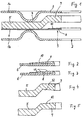
- Fig. 1 shows in section and sections of a cylinder head gasket.
- the cylinder head gasket shown in Fig. 1 comprises two cover plates 1a, 1b, of which the cover plate 1a in the installed state of the cylinder head gasket Cylinder head of the internal combustion engine for which the cylinder head gasket is designed, is turned while the cover plate 1b is facing the cylinder block.
- the Cover plates 1a, 1b are with one or usually several, side by side arranged openings 2 corresponding to the combustion chambers of the internal combustion engine Mistake.
- the cover plates 1a, 1b are also spaced around each opening 2 to this while leaving a straight sheet metal section 3 in the opening edge area provided with an annular bead 4 running around the respective opening 2, the beads 4 of the two cover plates 1a, 1b with their apices each other are turned.
- the carrier plate 5 is in the opening edge area provided with a cranked section 7, in the area of which by flanging of the crimped sheet 6 resulting crimped flange 8 is arranged.
- the folding flange 8 forms together with the sections of the Carrier plate 5 and the seaming flange 6 a travel limiter 9 of larger Total sheet thickness than in the remaining area of the cylinder head gasket, on the one hand serves to limit the travel of the associated bead (s) 4, and on the other hand forms a combustion chamber elevation at the edge of the combustion chamber, so that along of the opening edge area the highest pressure when clamped Cylinder head gasket prevails.
- the flanged seam flange 8 is here with a radially outward in it Provide decreasing thickness bevel 10 so that the surface pressure in the area of the travel limiter 9 across its width in the radial direction below Operating conditions, i.e. with the internal combustion engine running, this is heated accordingly, is substantially homogeneous. Here will expediently start from the most critical operating conditions, e.g. Full load. In the cold, installed state, the radially outer section of the Bevel 10 may not yet be under pressure.
- a bevel 10 of approximately 3/100 mm can be provided.
- the Bevel 10 can also be formed by steps 11, cf. Fig. 3. Simultaneously for this purpose, the steps can be chamfered. Expediently the height difference in the form of the bevel 10 and / or steps 11 by embossing manufactured.
- the crimping flange 8 usually pushes something into it Folding flange 6, see. Fig. 2.
- the carrier plate 5 is usually around a sheet of cold-rolled steel, while the cover sheets 1a, 1b of spring steel consist.
- the seaming flange 6 can also be applied to the seaming flange 8 Side should be designed to decrease in height radially outwards.
- the carrier plate 5 can in the area of the bent portion 7 one of the side facing the cover plate 1a or the folded flange plate 6 have corresponding bevel 12, while the folded area of the Folding flange 6 is practically constant in its strength, cf. 4, 5.
- the entire travel limiter 9 can also be solid on the carrier plate 5 corresponding deformation and decreasing in strength radially outwards or as inserted into a corresponding opening concentric with the opening 2, in its strength radially outwardly decreasing ring, where then a crimped sheet 6 is unnecessary.
- the cover plate 1b which faces the cylinder block, omitted.
- the cylinder head gasket can also be single-layer, i.e. only that beaded cover plate 1a include that on the side on which the apex of the Bead 4 is located, carries, for example, a welded-on travel limiter 9, which is bevelled accordingly.
- the travel limiter 9 or the seamed flange 6 is expediently rounded at opening 2 in the bending area to avoid edge pressure there.
Landscapes
- Engineering & Computer Science (AREA)
- General Engineering & Computer Science (AREA)
- Mechanical Engineering (AREA)
- Chemical & Material Sciences (AREA)
- Combustion & Propulsion (AREA)
- Gasket Seals (AREA)
Abstract
Description
Die Erfindung betrifft eine Zylinderkopfdichtung nach dem Oberbegriff des Anspruchs 1.The invention relates to a cylinder head gasket according to the preamble of Claim 1.
Aus EP 0 627 581 A1 ist eine derartige Zylinderkopfdichtung bekannt, bei der zwei gesickte Deckbleche mit einem dazwischen befindlichen Trägerblech vorgesehen sind, wobei ein sich entlang des Brennkammerrandes der Brennkraftmaschine erstreckender Federwegbegrenzer, auch als Stopper bezeichnet, der auch zur Brennraumüberhöhung dient, wodurch der Zylinderkopf der Brennkraftmaschine eine definierte Vorspannung beim Einspannen der Zylinderkopfdichtung entlang des Brennkammerrandes erhält, mit dem Trägerblech verschweißt ist. Um das Verschweißen zu erleichtern, ist der getrennt hergestellte Federwegbegrenzer zunächst im Schnitt trapezförmig ausgebildet und wird dann benachbart zum Brennkammerrand auf eine gewünschte Höhe flach gedrückt, so daß er zueinander parallele Auflageflächen für die planen Abschnitte der Deckbleche radial einwärts von den Sicken erhält. Dementsprechend wird mit der anfänglichen Trapezform keine Funktion der Zylinderkopfdichtung beeinflußt.Such a cylinder head gasket is known from EP 0 627 581 A1, in which two corrugated cover plates with a support plate located between them are, being along the edge of the combustion chamber of the internal combustion engine extending travel limiter, also called a stopper, which is also used for Excessive combustion chamber serves, whereby the cylinder head of the internal combustion engine Defined preload when clamping the cylinder head gasket along the Combustion chamber edge receives, is welded to the support plate. To do that The separately manufactured travel limiter is designed to make welding easier initially trapezoidal in section and is then adjacent to Combustion chamber edge pressed flat to a desired height so that it is facing each other parallel bearing surfaces for the flat sections of the cover plates radially inward from receives the beads. Accordingly, the initial trapezoidal shape does not Function of the cylinder head gasket is affected.
Bei Brennkraftmaschinen mit weniger steifen Zylinderköpfen, etwa aus einer Al-Legierung, wurde festgestellt, daß eine "Abrollbewegung" des Zylinderkopfes über die Breite des Federwegbegrenzers erfolgt. Dies hat zur Folge, daß es aufgrund hoher Kantenpressung zu Biege- und Schubspannungen in den Deckblechen und im Trägerblech der Zylinderkopfdichtung kommt, die letztlich zu Rissen in den Deckblechen und im Trägerblech führen können.In internal combustion engines with less rigid cylinder heads, for example made of an aluminum alloy, it was found that a "rolling movement" of the cylinder head over the Width of the travel limiter takes place. As a result, it is due to high Edge pressure to bending and shear stresses in the cover plates and in Carrier plate of the cylinder head gasket comes, which ultimately leads to cracks in the Cover plates and can lead in the carrier plate.
Aus DE 196 01 324 A1 ist ebenfalls eine metallische Zylinderkopfdichtung der eingangs genannten Art bekannt, bei der zwischen zwei gesickten Deckblechen ein Falzbördelblech vorgesehen ist, dessen Umbiegungsendabschnitt sich in Radialrichtung der Brennkammeröffnung vor den Rändern der Deckbleche befindet, so daß dieser keiner Pressung unterworfen wird. Der bezüglich der Sicken wirksame Teil des Umbiegungsabschnittes hat gleichbleibende Dicke.From DE 196 01 324 A1 is also a metallic cylinder head gasket type mentioned at the beginning, in which between two corrugated cover plates Folded flange is provided, the bending end portion of which is in Radial direction of the combustion chamber opening is in front of the edges of the cover plates, so that this is not subjected to pressure. The effective part regarding the beads of the bending section has a constant thickness.
Aus DE 195 31 232 C2 ist eine metallische Zylinderkopfdichtung der eingangs genannten Art bekannt, bei der der den Federwegbegrenzer gleichbleibender Dicke für die Sicken der Deckbleche bildende umgebördelte Bereich des Falzbördelblechs im Stegbereich zwischen den Brennkammer-öffnungen, wenn dieser sehr schmal ist, weggelassen ist.From DE 195 31 232 C2 is a metallic cylinder head gasket at the beginning Known type known, in which the travel of the travel limiter constant thickness the beads of the cover plates forming the flanged area of the folded flange in Web area between the combustion chamber openings, if this is very narrow, is omitted.
Aufgabe der Erfindung ist es daher, eine Zylinderkopfdichtung nach dem Oberbegriff des Anspruchs 1 zu schaffen, deren Lebensdauer durch eine Abrollbewegung des Zylinderkopfes über die Breite des Federwegbegrenzers möglichst wenig beeinträchtigt wird.The object of the invention is therefore to provide a cylinder head gasket Generic preamble of claim 1, the lifespan of which Rolling movement of the cylinder head across the width of the travel limiter is affected as little as possible.
Diese Aufgabe wird entsprechend dem kennzeichnenden Teil des Anspruchs 1 gelöst.This object is in accordance with the characterizing part of claim 1 solved.
Durch entsprechendes Abschrägen des Federwegbegrenzers wird die Kantenpressung reduziert. Dies hat zur Folge, daß die Biege- und Schubspannungen in dem wenigstens einen Deckblech und in einem gegebenenfalls vorhandenen Trägerblech reduziert werden können. Somit kann die Gefahr von Rissen in den Deckblechen und im Trägerblech vermindert werden. Anstelle einer Linienauflage bzw. -pressung ergibt sich eine flächige Auflage und somit eine geringere partielle Pressung zwischen Zylinderkopf und zugewandtem Deckblech und daraus resultierend ein geringerer Verschleiß. Der Federwegbegrenzer ist somit an die Deformation des Zylinderkopfes angepaßt.By appropriately chamfering the travel limiter Edge pressure reduced. This has the consequence that the bending and shear stresses in the at least one cover plate and in an existing one Carrier sheet can be reduced. Thus, the risk of cracks in the Cover plates and be reduced in the carrier plate. Instead of a line support or -pressure results in a flat support and thus a lower partial pressure between the cylinder head and the facing cover plate and the resulting one less wear. The travel limiter is thus at the deformation of the Adjusted cylinder head.
Hierbei ist durch eine entsprechende Änderung des Winkels der Abschrägung eine Anpassung an verschiedene Zylinderkopfsteifigkeiten möglich. Der Winkel der Abschrägung wird dabei über Einspannversuche ermittelt.Here is a corresponding change in the angle of the bevel an adaptation to different cylinder head stiffness possible. The angle of the The bevel is determined using clamping tests.
Weitere Ausgestaltungen der Erfindung sind der nachfolgenden Beschreibung und den Unteransprüchen zu entnehmen.Further embodiments of the invention are the following description and the subclaims.
Die Erfindung wird nachstehend anhand von in den beigefügten Abbildungen dargestellten Ausführungsbeispielen näher erläutert.The invention is illustrated below in the accompanying figures illustrated embodiments explained in more detail.
Fig. 1 zeigt im Schnitt und ausschnittweise eine Zylinderkopfdichtung.Fig. 1 shows in section and sections of a cylinder head gasket.
Fig. 2 bis 5 zeigen ausschnittweise weitere Ausführungsformen im Schnitt.2 to 5 show sections of further embodiments in section.
Die in Fig. 1 dargestellte Zylinderkopfdichtung umfaßt zwei Deckbleche 1a, 1b,
von denen das Deckblech 1a im eingebauten Zustand der Zylinderkopfdichtung dem
Zylinderkopf der Brennkraftmaschine, für die die Zylinderkopfdichtung konzipiert ist,
zugekehrt ist, während das Deckblech 1b dem Zylinderblock zugewandt ist. Die
Deckbleche 1a, 1b sind mit einer oder üblicherweise mit mehreren, nebeneinander
angeordneten Öffnungen 2 entsprechend den Brennkammern der Brennkraftmaschine
versehen. Die Deckbleche 1a, 1b sind zudem um jede Öffnung 2 herum mit Abstand
zu dieser unter Belassung eines geraden Blechabschnitts 3 im Öffnungsrandbereich
mit einer um die jeweilige Öffnung 2 umlaufenden, ringförmigen Sicke 4 versehen,
wobei die Sicken 4 der beiden Deckbleche 1a, 1b mit ihren Scheiteln einander
zugekehrt sind.The cylinder head gasket shown in Fig. 1 comprises two cover plates 1a, 1b,
of which the cover plate 1a in the installed state of the cylinder head gasket
Cylinder head of the internal combustion engine for which the cylinder head gasket is designed,
is turned while the cover plate 1b is facing the cylinder block. The
Cover plates 1a, 1b are with one or usually several, side by side
arranged openings 2 corresponding to the combustion chambers of the internal combustion engine
Mistake. The cover plates 1a, 1b are also spaced around each opening 2
to this while leaving a straight
Zwischen den beiden Deckblechen 1a, 1b befindet sich eine Zwischenlage, die
bei dem in Fig. 1 dargestellten Ausführungsbeispiel aus einem Trägerblech 5 und
einem Falzbördelblech 6 gebildet wird. Das Trägerblech 5 ist im Öffnungsrandbereich
mit einem gekröpften Abschnitt 7 versehen, in dessen Bereich ein durch Umbördeln
des Falzbördelblechs 6 entstandener Falzbördel 8 angeordnet ist. Der Falzbördel 8
bildet zusammen mit den darüber und darunter befindlichen Abschnitten des
Trägerblechs 5 und des Falzbördelblechs 6 einen Federwegbegrenzer 9 von größerer
Gesamtblechstärke als im übrigen Bereich der Zylinderkopfdichtung, der einerseits
dazu dient, den Federweg der zugehörigen Sicke(n) 4 zu begrenzen, und
andererseits am Brennkammerrand eine Brennraumüberhöhung bildet, so daß entlang
des Öffnungsrandbereichs der höchste Pressungsdruck bei eingespannter
Zylinderkopfdichtung herrscht.There is an intermediate layer between the two cover plates 1a, 1b
in the embodiment shown in Fig. 1 from a
Der umgebördelte Falzbördel 8 ist hierbei mit einer sich radial auswärts in ihrer
Dicke abnehmend Abschrägung 10 versehen, so daß die Flächenpressung im Bereich
des Federwegbegrenzers 9 über dessen Breite in radialer Richtung unter
Betriebsbedingungen, d.h. bei laufender Brennkraftmaschine, bei der diese
entsprechend erwärmt ist, im wesentlichen homogen ist. Hierbei wird
zweckmäßigerweise von den kritischsten Betriebsbedingungen ausgegangen, z.B.
Vollast. Im kalten, eingebauten Zustand steht der radial äußere Abschnitt der
Abschrägung 10 gegebenenfalls noch nicht unter Pressung.The
Als Falzbördelblech 6 wird üblicherweise ein (Edelstahl-)Blech einer Stärke von
etwa 0,12 bis 0,15 mm verwendet, wobei beispielsweise über eine Falzbördelbreite
von 2,5 mm eine Abschrägung 10 von etwa 3/100 mm vorgesehen sein kann. Die
Abschrägung 10 kann auch durch Stufen 11 gebildet sein, vgl. Fig. 3. Gleichzeitig
hierzu kann eine Abschrägung der Stufen vorgesehen sein. Zweckmäßigerweise wird
die Höhendifferenz in Form der Abschrägung 10 und/oder Stufen 11 durch Prägen
hergestellt. Hierbei drückt sich gewöhnlich der Falzbördel 8 etwas in das
Falzbördelblech 6 ein, vgl. Fig. 2. Bei dem Trägerblech 5 handelt es sich üblicherweise
um ein Blech aus kaltgewalztem Stahl, während die Deckbleche 1a, 1b aus Federstahl
bestehen.Usually a (stainless steel) sheet with a thickness of
used about 0.12 to 0.15 mm, for example over a seam flare width
of 2.5 mm, a
Das Falzbördelblech 6 kann aber auch an der dem Falzbördel 8 angewandten
Seite entsprechend radial nach außen in der Höhe abnehmend ausgebildet sein.The
Ferner kann das Trägerblech 5 im Bereich des abgekröpften Abschnitts 7 an
der dem Deckblech 1a oder dem Falzbördelblech 6 zugewandten Seite eine
entsprechende Abschrägung 12 aufweisen, während der umgefalzte Bereich des
Falzbördelblechs 6 in seiner Stärke praktisch gleichbleibend ist, vgl. Fig. 4, 5.Furthermore, the
Der gesamte Federwegbegrenzer 9 kann auch massiv am Trägerblech 5 durch
entsprechende Verformung und in seiner Stärke radial nach außen hin abnehmend
oder als in eine entsprechende zur Öffnung 2 konzentrische Öffnung eingesetzter, in
seiner Stärke radial nach außen abnehmender Ring ausgebildet sein, wobei sich dann
ein Falzbördelblech 6 erübrigt.The
Gegebenenfalls kann das Deckblech 1b, das dem Zylinderblock zugewandt ist, entfallen.If necessary, the cover plate 1b, which faces the cylinder block, omitted.
Gegebenenfalls kann die Zylinderkopfdichtung auch einlagig sein, d.h. nur das
gesickte Deckblech 1a umfassen, das auf der Seite, auf der sich der Scheitel der
Sicke 4 befindet, einen beispielsweise aufgeschweißten Federwegbegrenzer 9 trägt,
der entsprechend abgeschrägt ist.If necessary, the cylinder head gasket can also be single-layer, i.e. only that
beaded cover plate 1a include that on the side on which the apex of the
Zweckmäßigerweise ist der Federwegbegrenzer 9 bzw. das Falzbördelblech 6
im Biegebereich an der Öffnung 2 gerundet, um dort Kantenpressungen zu vermeiden.The
Claims (9)
Applications Claiming Priority (2)
| Application Number | Priority Date | Filing Date | Title |
|---|---|---|---|
| DE19822143 | 1998-05-16 | ||
| DE1998122143 DE19822143C9 (en) | 1998-05-16 | 1998-05-16 | Cylinder head gasket |
Publications (3)
| Publication Number | Publication Date |
|---|---|
| EP0959274A2 true EP0959274A2 (en) | 1999-11-24 |
| EP0959274A3 EP0959274A3 (en) | 2000-07-19 |
| EP0959274B1 EP0959274B1 (en) | 2004-12-29 |
Family
ID=7868082
Family Applications (1)
| Application Number | Title | Priority Date | Filing Date |
|---|---|---|---|
| EP19990109598 Revoked EP0959274B1 (en) | 1998-05-16 | 1999-05-14 | Cylinder head gasket |
Country Status (2)
| Country | Link |
|---|---|
| EP (1) | EP0959274B1 (en) |
| DE (2) | DE19822143C9 (en) |
Cited By (2)
| Publication number | Priority date | Publication date | Assignee | Title |
|---|---|---|---|---|
| DE102005039060A1 (en) * | 2005-08-18 | 2007-03-01 | Federal-Mogul Sealing Systems Gmbh | Cylinder head gasket for internal combustion engine, has stopper unit staying with defined breadth with support layer in support contact, in area of free shank of support layer, so that gap is formed around edge of passage opening |
| DE102014215596A1 (en) | 2014-08-06 | 2016-02-11 | Elringklinger Ag | Cylinder head gasket and combination of a cylinder head gasket and an internal combustion engine |
Families Citing this family (3)
| Publication number | Priority date | Publication date | Assignee | Title |
|---|---|---|---|---|
| DE10130329A1 (en) * | 2001-06-22 | 2003-01-23 | Federal Mogul Sealing Sys Spa | Process for manufacturing a flat gasket and flat gasket |
| DE102008006675A1 (en) * | 2008-01-30 | 2009-08-13 | Federal-Mogul Sealing Systems Gmbh | gasket |
| DE102008061684B4 (en) * | 2008-12-11 | 2014-12-04 | Acs Coating Systems Gmbh | Flat elastically deformable element |
Citations (3)
| Publication number | Priority date | Publication date | Assignee | Title |
|---|---|---|---|---|
| EP0627581A1 (en) | 1992-06-09 | 1994-12-07 | Japan Metal Gasket Co., Ltd. | Metallic gasket |
| DE19601324A1 (en) | 1995-01-25 | 1996-08-14 | Nihon Metal Gasket | Engine cylinder head gasket |
| DE19531232A1 (en) | 1995-08-25 | 1997-02-27 | Elringklinger Gmbh | Metallic sealing gasket for internal combustion engine cylinder heads |
Family Cites Families (5)
| Publication number | Priority date | Publication date | Assignee | Title |
|---|---|---|---|---|
| JPS61255252A (en) * | 1985-05-09 | 1986-11-12 | Nippon Metal Gasket Kk | Single-plate metal gasket |
| DE4219709C2 (en) * | 1992-06-16 | 2001-07-12 | Reinz Dichtungs Gmbh | Metallic flat gasket |
| DE19513361C1 (en) * | 1995-04-08 | 1996-06-27 | Elringklinger Gmbh | Metallic cylinder head gasket for IC engine |
| DE19520695C1 (en) * | 1995-06-07 | 1996-07-04 | Elringklinger Gmbh | Metallic cylinder head gasket for IC engine |
| DE19654283A1 (en) * | 1996-12-24 | 1998-06-25 | Reinz Dichtungs Gmbh | Metallic flat gasket |
-
1998
- 1998-05-16 DE DE1998122143 patent/DE19822143C9/en not_active Expired - Fee Related
-
1999
- 1999-05-14 EP EP19990109598 patent/EP0959274B1/en not_active Revoked
- 1999-05-14 DE DE59911351T patent/DE59911351D1/en not_active Expired - Lifetime
Patent Citations (3)
| Publication number | Priority date | Publication date | Assignee | Title |
|---|---|---|---|---|
| EP0627581A1 (en) | 1992-06-09 | 1994-12-07 | Japan Metal Gasket Co., Ltd. | Metallic gasket |
| DE19601324A1 (en) | 1995-01-25 | 1996-08-14 | Nihon Metal Gasket | Engine cylinder head gasket |
| DE19531232A1 (en) | 1995-08-25 | 1997-02-27 | Elringklinger Gmbh | Metallic sealing gasket for internal combustion engine cylinder heads |
Cited By (2)
| Publication number | Priority date | Publication date | Assignee | Title |
|---|---|---|---|---|
| DE102005039060A1 (en) * | 2005-08-18 | 2007-03-01 | Federal-Mogul Sealing Systems Gmbh | Cylinder head gasket for internal combustion engine, has stopper unit staying with defined breadth with support layer in support contact, in area of free shank of support layer, so that gap is formed around edge of passage opening |
| DE102014215596A1 (en) | 2014-08-06 | 2016-02-11 | Elringklinger Ag | Cylinder head gasket and combination of a cylinder head gasket and an internal combustion engine |
Also Published As
| Publication number | Publication date |
|---|---|
| EP0959274A3 (en) | 2000-07-19 |
| DE19822143C5 (en) | 2005-04-21 |
| DE19822143C1 (en) | 1999-10-07 |
| EP0959274B1 (en) | 2004-12-29 |
| DE19822143C9 (en) | 2006-05-04 |
| DE59911351D1 (en) | 2005-02-03 |
Similar Documents
| Publication | Publication Date | Title |
|---|---|---|
| EP0747614B2 (en) | Metallic cylinder head gasket | |
| EP0877183B1 (en) | Metallic cylinder head gasket | |
| DE69215460T2 (en) | Metal seal and manufacturing process therefor | |
| EP0939255B1 (en) | Cylinder head gasket | |
| EP1291561B1 (en) | Cylinder head gasket | |
| EP1643170B1 (en) | Flat gasket and method of making a flat gasket | |
| DE19808362C2 (en) | Flat gasket | |
| DE19822143C1 (en) | Cylinder head gasket for internal combustion engine | |
| DE102006021499A1 (en) | Flat gasket, in particular cylinder head gasket | |
| EP0619447B1 (en) | Flat metallic gasket | |
| DE19513361C1 (en) | Metallic cylinder head gasket for IC engine | |
| EP0769616A1 (en) | Sealing system for internal combustion engines | |
| DE102008064044A1 (en) | Sealing system and cylinder head gasket for a reciprocating internal combustion engine | |
| DE19531232C2 (en) | Metallic cylinder head gasket | |
| EP2138745B1 (en) | Cylinder head gasket | |
| DE19934825C1 (en) | Gasket seal for IC motor cylinder heads has cut rectangular sections at the center carrier sheet around the cylinder openings to cover the raised sections at the combustion zones without additional welded rings | |
| DE112019003842T5 (en) | SELF-FORMING SEAL ARRANGEMENT AND PROCEDURE FOR ITS CONSTRUCTION AND ASSEMBLY | |
| DE19725986A1 (en) | Metallic cylinder head gasket | |
| DE102004061964B4 (en) | gasket | |
| DE19523825A1 (en) | Metallic flat packing, esp. cylinder head gasket for IC engine | |
| DE19549593C2 (en) | Cylinder head gasket | |
| DE19924260C2 (en) | Metallic flat gasket | |
| DE19548574C2 (en) | Metallic cylinder head gasket | |
| DE102013101253A1 (en) | Cylinder head gasket for sealing seam i.e. circular arc, has sealing plate provided with seal assembly to surround deformation delimiter by engine operation during spring travel of support element seam | |
| EP0780561B2 (en) | Cylinder head gasket |
Legal Events
| Date | Code | Title | Description |
|---|---|---|---|
| PUAI | Public reference made under article 153(3) epc to a published international application that has entered the european phase |
Free format text: ORIGINAL CODE: 0009012 |
|
| AK | Designated contracting states |
Kind code of ref document: A2 Designated state(s): DE FR GB IT |
|
| AX | Request for extension of the european patent |
Free format text: AL;LT;LV;MK;RO;SI |
|
| PUAL | Search report despatched |
Free format text: ORIGINAL CODE: 0009013 |
|
| AK | Designated contracting states |
Kind code of ref document: A3 Designated state(s): AT BE CH CY DE DK ES FI FR GB GR IE IT LI LU MC NL PT SE |
|
| AX | Request for extension of the european patent |
Free format text: AL;LT;LV;MK;RO;SI |
|
| 17P | Request for examination filed |
Effective date: 20001110 |
|
| AKX | Designation fees paid |
Free format text: DE FR GB IT |
|
| RAP1 | Party data changed (applicant data changed or rights of an application transferred) |
Owner name: ELRINGKLINGER AG |
|
| 17Q | First examination report despatched |
Effective date: 20030715 |
|
| GRAP | Despatch of communication of intention to grant a patent |
Free format text: ORIGINAL CODE: EPIDOSNIGR1 |
|
| GRAA | (expected) grant |
Free format text: ORIGINAL CODE: 0009210 |
|
| GRAS | Grant fee paid |
Free format text: ORIGINAL CODE: EPIDOSNIGR3 |
|
| AK | Designated contracting states |
Kind code of ref document: B1 Designated state(s): DE FR GB IT |
|
| REG | Reference to a national code |
Ref country code: GB Ref legal event code: FG4D Free format text: NOT ENGLISH |
|
| REF | Corresponds to: |
Ref document number: 59911351 Country of ref document: DE Date of ref document: 20050203 Kind code of ref document: P |
|
| GBT | Gb: translation of ep patent filed (gb section 77(6)(a)/1977) |
Effective date: 20050413 |
|
| PLBI | Opposition filed |
Free format text: ORIGINAL CODE: 0009260 |
|
| 26 | Opposition filed |
Opponent name: FEDERAL MOGULSEALING SYSTEMS GMBH Effective date: 20050823 |
|
| PLAX | Notice of opposition and request to file observation + time limit sent |
Free format text: ORIGINAL CODE: EPIDOSNOBS2 |
|
| ET | Fr: translation filed | ||
| PLAF | Information modified related to communication of a notice of opposition and request to file observations + time limit |
Free format text: ORIGINAL CODE: EPIDOSCOBS2 |
|
| PLBB | Reply of patent proprietor to notice(s) of opposition received |
Free format text: ORIGINAL CODE: EPIDOSNOBS3 |
|
| PGFP | Annual fee paid to national office [announced via postgrant information from national office to epo] |
Ref country code: IT Payment date: 20090525 Year of fee payment: 11 Ref country code: FR Payment date: 20090513 Year of fee payment: 11 |
|
| RDAF | Communication despatched that patent is revoked |
Free format text: ORIGINAL CODE: EPIDOSNREV1 |
|
| APAH | Appeal reference modified |
Free format text: ORIGINAL CODE: EPIDOSCREFNO |
|
| APBM | Appeal reference recorded |
Free format text: ORIGINAL CODE: EPIDOSNREFNO |
|
| APBP | Date of receipt of notice of appeal recorded |
Free format text: ORIGINAL CODE: EPIDOSNNOA2O |
|
| PGFP | Annual fee paid to national office [announced via postgrant information from national office to epo] |
Ref country code: GB Payment date: 20100519 Year of fee payment: 12 |
|
| APBQ | Date of receipt of statement of grounds of appeal recorded |
Free format text: ORIGINAL CODE: EPIDOSNNOA3O |
|
| REG | Reference to a national code |
Ref country code: FR Ref legal event code: ST Effective date: 20110131 |
|
| PG25 | Lapsed in a contracting state [announced via postgrant information from national office to epo] |
Ref country code: IT Free format text: LAPSE BECAUSE OF NON-PAYMENT OF DUE FEES Effective date: 20100514 |
|
| PG25 | Lapsed in a contracting state [announced via postgrant information from national office to epo] |
Ref country code: FR Free format text: LAPSE BECAUSE OF NON-PAYMENT OF DUE FEES Effective date: 20100531 |
|
| GBPC | Gb: european patent ceased through non-payment of renewal fee |
Effective date: 20110514 |
|
| PG25 | Lapsed in a contracting state [announced via postgrant information from national office to epo] |
Ref country code: GB Free format text: LAPSE BECAUSE OF NON-PAYMENT OF DUE FEES Effective date: 20110514 |
|
| PGFP | Annual fee paid to national office [announced via postgrant information from national office to epo] |
Ref country code: DE Payment date: 20140521 Year of fee payment: 16 |
|
| REG | Reference to a national code |
Ref country code: DE Ref legal event code: R103 Ref document number: 59911351 Country of ref document: DE Ref country code: DE Ref legal event code: R064 Ref document number: 59911351 Country of ref document: DE |
|
| APBU | Appeal procedure closed |
Free format text: ORIGINAL CODE: EPIDOSNNOA9O |
|
| RDAG | Patent revoked |
Free format text: ORIGINAL CODE: 0009271 |
|
| STAA | Information on the status of an ep patent application or granted ep patent |
Free format text: STATUS: PATENT REVOKED |
|
| 27W | Patent revoked |
Effective date: 20150212 |
|
| REG | Reference to a national code |
Ref country code: DE Ref legal event code: R107 Ref document number: 59911351 Country of ref document: DE |