EP0959271B1 - Actionneur hélicoidal de câble de changement de vitesse - Google Patents
Actionneur hélicoidal de câble de changement de vitesse Download PDFInfo
- Publication number
- EP0959271B1 EP0959271B1 EP99201174A EP99201174A EP0959271B1 EP 0959271 B1 EP0959271 B1 EP 0959271B1 EP 99201174 A EP99201174 A EP 99201174A EP 99201174 A EP99201174 A EP 99201174A EP 0959271 B1 EP0959271 B1 EP 0959271B1
- Authority
- EP
- European Patent Office
- Prior art keywords
- set forth
- shift
- mounting structure
- terminal
- supported
- Prior art date
- Legal status (The legal status is an assumption and is not a legal conclusion. Google has not performed a legal analysis and makes no representation as to the accuracy of the status listed.)
- Expired - Lifetime
Links
Images


Classifications
-
- F—MECHANICAL ENGINEERING; LIGHTING; HEATING; WEAPONS; BLASTING
- F16—ENGINEERING ELEMENTS AND UNITS; GENERAL MEASURES FOR PRODUCING AND MAINTAINING EFFECTIVE FUNCTIONING OF MACHINES OR INSTALLATIONS; THERMAL INSULATION IN GENERAL
- F16H—GEARING
- F16H61/00—Control functions within control units of change-speed- or reversing-gearings for conveying rotary motion ; Control of exclusively fluid gearing, friction gearing, gearings with endless flexible members or other particular types of gearing
- F16H61/26—Generation or transmission of movements for final actuating mechanisms
- F16H61/28—Generation or transmission of movements for final actuating mechanisms with at least one movement of the final actuating mechanism being caused by a non-mechanical force, e.g. power-assisted
- F16H61/32—Electric motors actuators or related electrical control means therefor
- F16H2061/326—Actuators for range selection, i.e. actuators for controlling the range selector or the manual range valve in the transmission
-
- F—MECHANICAL ENGINEERING; LIGHTING; HEATING; WEAPONS; BLASTING
- F16—ENGINEERING ELEMENTS AND UNITS; GENERAL MEASURES FOR PRODUCING AND MAINTAINING EFFECTIVE FUNCTIONING OF MACHINES OR INSTALLATIONS; THERMAL INSULATION IN GENERAL
- F16H—GEARING
- F16H59/00—Control inputs to control units of change-speed-, or reversing-gearings for conveying rotary motion
- F16H59/02—Selector apparatus
- F16H59/08—Range selector apparatus
- F16H59/10—Range selector apparatus comprising levers
-
- F—MECHANICAL ENGINEERING; LIGHTING; HEATING; WEAPONS; BLASTING
- F16—ENGINEERING ELEMENTS AND UNITS; GENERAL MEASURES FOR PRODUCING AND MAINTAINING EFFECTIVE FUNCTIONING OF MACHINES OR INSTALLATIONS; THERMAL INSULATION IN GENERAL
- F16H—GEARING
- F16H61/00—Control functions within control units of change-speed- or reversing-gearings for conveying rotary motion ; Control of exclusively fluid gearing, friction gearing, gearings with endless flexible members or other particular types of gearing
- F16H61/26—Generation or transmission of movements for final actuating mechanisms
- F16H61/36—Generation or transmission of movements for final actuating mechanisms with at least one movement being transmitted by a cable
-
- Y—GENERAL TAGGING OF NEW TECHNOLOGICAL DEVELOPMENTS; GENERAL TAGGING OF CROSS-SECTIONAL TECHNOLOGIES SPANNING OVER SEVERAL SECTIONS OF THE IPC; TECHNICAL SUBJECTS COVERED BY FORMER USPC CROSS-REFERENCE ART COLLECTIONS [XRACs] AND DIGESTS
- Y10—TECHNICAL SUBJECTS COVERED BY FORMER USPC
- Y10T—TECHNICAL SUBJECTS COVERED BY FORMER US CLASSIFICATION
- Y10T74/00—Machine element or mechanism
- Y10T74/19—Gearing
- Y10T74/19219—Interchangeably locked
- Y10T74/19251—Control mechanism
-
- Y—GENERAL TAGGING OF NEW TECHNOLOGICAL DEVELOPMENTS; GENERAL TAGGING OF CROSS-SECTIONAL TECHNOLOGIES SPANNING OVER SEVERAL SECTIONS OF THE IPC; TECHNICAL SUBJECTS COVERED BY FORMER USPC CROSS-REFERENCE ART COLLECTIONS [XRACs] AND DIGESTS
- Y10—TECHNICAL SUBJECTS COVERED BY FORMER USPC
- Y10T—TECHNICAL SUBJECTS COVERED BY FORMER US CLASSIFICATION
- Y10T74/00—Machine element or mechanism
- Y10T74/20—Control lever and linkage systems
- Y10T74/20012—Multiple controlled elements
- Y10T74/20018—Transmission control
- Y10T74/2003—Electrical actuator
-
- Y—GENERAL TAGGING OF NEW TECHNOLOGICAL DEVELOPMENTS; GENERAL TAGGING OF CROSS-SECTIONAL TECHNOLOGIES SPANNING OVER SEVERAL SECTIONS OF THE IPC; TECHNICAL SUBJECTS COVERED BY FORMER USPC CROSS-REFERENCE ART COLLECTIONS [XRACs] AND DIGESTS
- Y10—TECHNICAL SUBJECTS COVERED BY FORMER USPC
- Y10T—TECHNICAL SUBJECTS COVERED BY FORMER US CLASSIFICATION
- Y10T74/00—Machine element or mechanism
- Y10T74/20—Control lever and linkage systems
- Y10T74/20012—Multiple controlled elements
- Y10T74/20018—Transmission control
- Y10T74/20049—Transmission controlled by flexible cable
-
- Y—GENERAL TAGGING OF NEW TECHNOLOGICAL DEVELOPMENTS; GENERAL TAGGING OF CROSS-SECTIONAL TECHNOLOGIES SPANNING OVER SEVERAL SECTIONS OF THE IPC; TECHNICAL SUBJECTS COVERED BY FORMER USPC CROSS-REFERENCE ART COLLECTIONS [XRACs] AND DIGESTS
- Y10—TECHNICAL SUBJECTS COVERED BY FORMER USPC
- Y10T—TECHNICAL SUBJECTS COVERED BY FORMER US CLASSIFICATION
- Y10T74/00—Machine element or mechanism
- Y10T74/20—Control lever and linkage systems
- Y10T74/20396—Hand operated
- Y10T74/20402—Flexible transmitter [e.g., Bowden cable]
- Y10T74/20456—Specific cable or sheath structure
Definitions
- This invention relates to an electric shift apparatus for shifting a vehicle transmission. More specifically, the invention relates to a motor driven drive assembly for driving a helical cable for linear actuation of a transmission shift lever.
- a typical automatic transmission receives input from a driver via a mode select lever that is movable between various shift positions, such as drive, reverse, park, or neutral.
- this mode select lever is connected to a cable or linkage assembly that extends to a transmission shift lever.
- the cable or linkage assembly actuates the transmission shift lever which causes the transmission to shift into the desired gear.
- An electric shift apparatus for a shifting a vehicle transmission assembly comprising a mounting structure adapted to be mounted to a vehicle structure, an electric motor supported by the mounting structure, and a drive assembly operably driven by the electric motor.
- the apparatus further includes a core element movably supported by the mounting structure and a guide for guiding the core element.
- a terminal is slidably disposed in the guide and connected to the core element.
- a shift lever is movable between a plurality of shift positions and connected to the terminal for shifting a transmission.
- the apparatus is characterized by the core element comprising a helical cable which is driven by the drive assembly for linear actuation of the shift lever.
- the subject invention provides, an electronic shift apparatus that is easily attached to almost any transmission and that is less expensive than prior art systems.
- the system is also compact, which increases the packaging space available for other vehicle components.
- the subject invention also provides flexible mounting for the electric shift apparatus as it can be located close to the transmission shift lever or up to several inches away from the lever, depending on what packaging space is available.
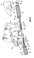
- an electric shift apparatus is shown generally at 10 in Figure 1.
- the electric shift apparatus 10 controls the shifting of a vehicle transmission 12 among various transmission shift positions.
- the transmission 12 receives input torque and speed from an engine 14 and transmits output torque to a vehicle driveline (not shown).
- the shifting of the transmission among the various shift positions increases, decreases, or eliminates the output torque to the driveline depending on which shift position has been selected.
- the electric shift apparatus 10 is electrically connected to a mode select lever 16 by an electrical connector 18 well known in the art.
- the mode select lever 16 is operated by a driver (not shown) who moves the mode select lever 16 among a plurality of shift positions, such as park, reverse, neutral, drive, or low gear, for example. Once the driver selects a desired shift position, the electric shift apparatus 10 is activated and the transmission 12 is shifted into the desired shift position.
- the electric shift apparatus 10 includes a mounting structure 20 adapted to be mounted to a vehicle structure such as a transmission housing 22 , for example.
- the mounting structure 20 is preferably mounted to the transmission housing 22 but could also be mounted to any other vehicle structure depending on what packaging space is available.
- the electric shift apparatus 10 also includes an electric motor 24 that is supported by the mounting structure 22 and a drive assembly 26 that is operably driven by the electric motor 24 , shown in Figure 2.
- a core element 28 is movably supported by the mounting structure 20 and is guided by a guide member 30 .
- a terminal 32 is slidably disposed in the guide member 30 and connected to the core element 28 .
- the terminal 32 is connected to a shift lever 34 which is pivotally supported on the transmission 12.
- the shift lever 34 shifts the gears (not shown) housed within the transmission 12 and is movable between a plurality of shift positions.
- the core element 28 of the electric shift apparatus 10 is comprised of a helical cable 36 driven by the drive assembly 26 for linear actuation of the shift lever 34 .
- the helical cable 36 is comprised of a filamentous member 38 and a core member 40 , defining a longitudinal axis 42 .
- the filamentous member 38 is wound about the core member 40 along the longitudinal axis.
- the filamentous member 38 is wound in spaced convolutions to define tooth-like members 44 that are spaced apart from one another along the core member 40 .
- the tooth-like members 44 are in driven engagement with the drive assembly 26 .
- the drive assembly 26 is shown in more detail in Figure 3.
- the drive assembly 26 is preferably comprised of a worm gear 46 and a worm wheel 48 .
- the electric motor 24 includes an output shaft 50 , shown in Figure 2, for driving the worm gear 46.
- the worm gear 46 drives the worm wheel 48 which is fixedly supported on a support shaft 52 .
- the support shaft 52 is spaced apart from and orientated perpendicularly to the output shaft 50 .
- a worm gear assembly is the preferred drive assembly 26 because due to the orientation of the electric motor 24 , the worm gear assembly is used to driveably connect the output shaft 52 to the nonparallel and nonintersecting support shaft 50 .
- the drive assembly 26 preferably further includes a pinion gear 54 for driving the helical cable 36 .
- the pinion gear 54 is also fixedly supported on the support shaft 52 and is spaced apart from the worm wheel 48 , thus the worm wheel 48 and pinion gear 54 rotate together.
- the electric motor 24 drives the worm gear 46 which drives the worm wheel 48 which causes the pinion gear 54 to rotate such that the pinion gear 54 engages the tooth-like members 44 of the helical cable 36 .
- the cable 36 is caused to move in either of two directions along a linear path.
- gearing assembly 26 could be configured such that the pinion gear 54 is eliminated and the worm wheel 48 directly drives the cable 36 .
- the electric motor could be repositioned such that a spur gear type assembly could be used to drive the helical cable 36 instead of a worm gear assembly, for example.
- the electric shift apparatus 10 includes a controller 56 , shown in Figure 1, for transmitting a shift selection signal indicating a desired shift position that has been selected by the driver to the electric motor 24 to adjust the shift lever 34 to achieve the desired shift position.
- the controller 56 is shown mounted adjacent to the mode select lever 16 , however, the controller 56 could be located anywhere in the vehicle.
- a sensor 58 is used to determine the longitudinal position of the helical cable 36 .
- the sensor 58 also transmits a cable position signal to the controller 56 for modifying the shift selection signal.
- the longitudinal position of the helical cable 36 is monitored to determine what shift position the transmission shift lever 34 is currently in.
- the current transmission shift lever position is compared to the shift selection signal initiated by the driver's input to ensure that the shift position selected by the driver is proper.
- the shift selection signal is compared to the cable position signal to ensure that the shift position selected by the driver corresponds to the shift position that the shift lever 34 is in.
- a preferred electrical drive circuit for comparing the cable position signal and the shift selection signal will be discussed in more detail below.
- the sensor 58 is a potentiometer which measures rotation of the worm wheel 48 and produces a rotation signal. The cable position signal would then be derived from the rotation signal.
- the potentiometer sensor 58 is supported by the mounting structure 20 and positioned concentrically with the worm wheel 48 .
- the potentiometer could be positioned and supported in other locations on the mounting structure 20 .
- the potentiometer could be used to measure the rotation of the pinion gear 54 or could be used to measure the linear movement of the helical cable 36 itself. While a potentiometer is the preferred sensor 58 , other sensors known in the art could be used to determine the position of the helical cable 36.
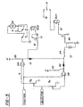
- a preferred electrical drive circuit utilizes the input from the mode select lever 16 and input from the sensor 5 8 and compares the cable position signal and the shift selection signal to power the electric motor 24 to control the shifting of the gears in the transmission 12 .
- the first input is the output voltage, i.e. the cable position signal, from the sensor 58 which is proportional to the position of the cable 36 and communicates to the controller 56 whether the cable 36 is in the requested position.
- the second input is the voltage input from the driver as the mode select lever 16 is actuated, i.e., the shift selection signal.
- the second input can be one of a plurality of unique voltages that correspond to a specific gear position selected by the driver. In other words, there is a reference voltage associated with the park position that is different than the reference voltage associated with the reverse position that is different than the reference voltage associated with the drive position, etc.
- the drive circuit also has two (2) outputs.
- the first output is a power signal that powers the electric motor 24 .
- the second output is a direction control signal that communicates to the electric motor 24 what direction to drive the helical cable 36 .
- Both the cable position signal and the shift selection signal are communicated to two (2) comparators U1A, U1B.
- comparator U1A goes high, producing a direction control signal that causes the helical cable 36 to move in the specified direction.
- a path is provided from the comparator U1A to a timing circuit associated with the second output, i.e. the motor control.
- a certain pre-determined amount of time is needed to determine which direction the motor should be operation in. Once the predetermined time has passed and the direction control signal has been produced, the second output is energized to power the electric motor 24 .
- the comparator U1B will go high, thus powering the motor 24 .
- the shift selection signal exceeds the second pre-determined voltage, power is no longer supplied to the motor 24 and the motor is grounded.
- the preferred drive circuit also includes the following components: two (2) diodes D1 and D2; seven (7) resistors R1 (preferably with 1k of resistance), R2 (preferably with 1k of resistance), R3 (preferably with 1k of resistance), R4 (preferably with 15k of resistance), R5 (preferably with 100k of resistance), R6 (preferably with 10k of resistance), and R7 (preferably with 10k of resistance); two transistors Q1 and Q2; two (2) relays RLY1 and RLY2; and one (1) capacitor (preferably 2200 pf). It should be understood that while the above values are preferred, other values can be used.
- the guide 30 is comprised of a tube 60 which is supported by the mounting structure 20 for swivelling movement relative thereto.
- This swivel tube 60 configuration is used to compensate for any angular movement between the shift lever 34 and the mounting structure 20 .
- the tube 60 includes a spherical end 62 and a distal end 64 located opposite from the spherical end 62 .
- the mounting structure 20 includes an integral female pocket 66 that rotatably supports the spherical end 62 of the tube 60 .
- the distal end 64 of the tube 60 is slidably supported on the terminal 30 .
- the terminal 32 includes a first end 68 and a second end 70 .
- the first end 68 is in sliding engagement with the tube 60 and the second end 70 is attached to the shift lever 34 .
- the shift lever 34 is rotatably attached to the transmission 12 at one end and includes a ball stud 72 at its other end.
- the second end 70 of the terminal 32 is, preferably snap fit onto the ball stud 72 , however, other attachment methods known in the art could be used.
- the terminal 32 further includes an outer surface 74 and an inner surface 76 .
- the outer surface 74 slidably engages the tube 60 and the inner surface 76 includes a crimp section 78 deformed into gripping engagement with the helical cable 36 .
- Crimping the terminal 32 onto the helical cable 36 is just one method of attachment, other attachment methods well known in the art could also be used.
- a covering 80 is used to enclose the terminal 32 in order to prevent dirt and other contaminants from interfering with the sliding engagement between the terminal 32 and the tube 60 .
- the covering 80 is preferably made from a flexible material such as rubber, that can extend and retract as the shift lever 34 is rotated with respect to the transmission 12 .
- the covering 80 has a first end 82 that is attached to the tube 60 and a second end 84 that is attached to the terminal 32 near its second end 70 .
- the covering 80 is attached to the terminal 32 and the tube 60 by means well known in the art, such as by clamps 86 , for example.
- the covering 80 is preferably constructed as a rubber boot style covering made from an elastic material, however, other style coverings could be used.
- a second covering 88 is used to enclose the helical cable 36 to prevent dirt and other contaminants from interfering in the interface between the worm wheel 48 and the tooth-like members 44 of the helical cable 36 .
- This covering 88 is also preferably made from a flexible material such as rubber, that can be extended and retracted as the helical cable 36 moves along a linear path.
- the helical cable 36 includes a first end 90 and a second end 92 .
- the first end 90 of the cable 36 is attached to the terminal 30 while the second end 92 extends outwardly from the mounting structure 20 .
- a cap member 94 is supported on the second end 92 of the helical cable 36 for engagement with the covering 88 .
- the cap member 94 prevents the end 92 of the helical cable 36 from damaging the covering 88 .
- the second covering 88 is attached to the mounting structure 60 by a clamp 86 .
- the mounting structure 20 is adapted to be mounted to the transmission housing 22. This mounting is done by bolts 94 or other fastening means known in the art.
- the subject invention provides an electronic shift apparatus 10 that is easily attached to almost any transmission. This allows an electric shift feature to be easily implemented on current transmissions 12 without having to modify the transmission 12 itself.
- the apparatus 10 is also compact, which increases the packaging space available for other vehicle components, and can be flexibly mounted in the vehicle.
- the electric shift apparatus 10 has flexibility in mounting location, it can be located close to the transmission shift lever 34 or up to several inches away from the lever, depending on what packaging space is available.
Landscapes
- Engineering & Computer Science (AREA)
- General Engineering & Computer Science (AREA)
- Mechanical Engineering (AREA)
- Gear-Shifting Mechanisms (AREA)
- Arrangement Or Mounting Of Control Devices For Change-Speed Gearing (AREA)
- Transmission Devices (AREA)
Claims (22)
- Appareil électrique de changement de vitesses (10) destiné à changer les vitesses d'une boíte de vitesses (12) sur un véhicule, comprenant :une structure de montage (20) susceptible d'être montée sur le corps d'un véhicule ;un moteur électrique (24) supporté par la structure de montage (20) ;un ensemble d'entraínement (26) entraíné par le moteur électrique (24) ;un élément formant âme (28) supporté de façon mobile par la structure de montage (20) ;un guide (30) destiné à guider l'élément formant âme (28) ;une attache d'extrémité (32) montée coulissante dans le guide (30) et reliée à l'élément formant âme (28) ; etun levier de changement de vitesses (34) susceptible d'être déplacé dans plusieurs positions et relié à l'attache d'extrémité (32) pour changer les vitesses d'une boíte de vitesses (12) ;cet appareil (10) étant caractérisé en ce que l'élément formant âme (28) comprend un câble hélicoïdal (36) entraíné par l'ensemble d'entraínement (26) pour actionner linéairement le levier de changement de vitesses (34).
- Appareil selon la revendication 1, dans lequel le câble hélicoïdal (36) comprend un élément filamenteux (38) et un élément formant âme (40) définissant un axe longitudinal (42), l'élément filamenteux (38) étant enroulé autour de l'élément formant âme (40) le long de cet axe longitudinal (42).
- Appareil selon la revendication 2, dans lequel l'élément filamenteux (38) est enroulé en spires espacées pour définir des éléments semblables à des dents (44) espacés les uns des autres le long de l'élément formant âme (40), les éléments semblables à des dents (44) engrenant avec l'ensemble d'entraínement (26).
- Appareil selon la revendication 2, comprenant un dispositif de commande (56) destiné à transmettre un signal de sélection de vitesse indiquant la vitesse souhaitée et choisie par un opérateur au moteur électrique (24) afin de régler le levier de changement de vitesses (34) pour obtenir la vitesse souhaitée.
- Appareil selon la revendication 4, dans lequel l'ensemble d'entraínement (26) comprend une vis sans fin (46) et une roue à vis sans fin (48).
- Appareil selon la revendication 5, dans lequel le moteur électrique (24) comprend un arbre de sortie (50) destiné à entraíner la vis sans fin (46).
- Appareil selon la revendication 6, comprenant un arbre (52) servant de support à la roue à vis sans fin (48), et dans lequel l'ensemble d'entraínement (26) comprend, en outre, un pignon (54) destiné à actionner le câble hélicoïdal (36), ce pignon (54) étant monté sur l'arbre (52) et espacé de la roue à vis sans fin (48).
- Appareil selon la revendication 5, comprenant un capteur (58) destiné à détecter la position longitudinale du câble hélicoïdal (36) et à transmettre un signal de position du câble au dispositif de commande (56) afin de modifier le signal de sélection de vitesse.
- Appareil selon la revendication 8, dans lequel le capteur (58) comprend un potentiomètre qui mesure la rotation de la roue à vis sans fin (48), ce qui produit un signal de rotation, le signal de position du câble étant dérivé de ce signal de rotation.
- Appareil selon la revendication 9, dans lequel le potentiomètre est disposé de manière concentrique à la roue à vis sans fin (48).
- Appareil selon la revendication 1, dans lequel le guide (30) comprend un tube (60) qui est supporté par la structure de montage (20) pour effectuer un pivotement par rapport à celle-ci.
- Appareil selon la revendication 11, dans lequel la structure de montage (20) comprend une poche (66) formée d'une seule pièce et le tube présente une extrémité sphérique (62) montée de façon rotative dans la poche (66).
- Appareil selon la revendication 12, dans lequel le tube (60) comprend une extrémité distale (64), à l'opposé de l'extrémité sphérique (62), qui est montée coulissante sur l'attache d'extrémité (32).
- Appareil selon la revendication 13, dans lequel l'attache d'extrémité (32) comprend une première extrémité (68) qui coopère de façon coulissante avec le tube (60) et une deuxième extrémité (70) montée sur le levier de changement de vitesses (34).
- Appareil selon la revendication 14, dans lequel le levier de changement de vitesses (34) comprend un pivot à rotule (72), la deuxième extrémité (70) de l'attache d'extrémité (32) étant enclenchée sur le pivot à rotule (72).
- Appareil selon la revendication 14, dans lequel l'attache d'extrémité (32) présente une surface extérieure (74) et une surface intérieure (76), la surface extérieure (74) étant destinée à coopérer avec le tube (60) et la surface intérieure (76) comprenant une section de sertissage (78) déformée pour saisir le câble hélicoïdal (36).
- Appareil selon la revendication 14, comprenant un élément de recouvrement (80) destiné à contenir l'attache d'extrémité (32), cet élément de recouvrement (80) étant monté sur la structure de montage (20).
- Appareil selon la revendication 17, dans lequel l'élément de recouvrement (80) est constitué en matériau flexible qui peut être allongé et rétracté lorsque le levier de changement de vitesses (34) tourne, l'élément de recouvrement (80) possédant une première extrémité (82) montée sur le tube (60) et une deuxième extrémité (84) montée de façon adjacente à la deuxième extrémité (70) de l'attache d'extrémité (32).
- Appareil selon la revendication 1, dans lequel le câble hélicoïdal (36) comprend une première extrémité (90) et une deuxième extrémité (92), la première extrémité (90) étant montée sur l'attache d'extrémité (32), et la deuxième extrémité (92) s'étendant en direction de l'extérieur à partir de la structure de montage (20).
- Appareil selon la revendication 19, comprenant un élément de recouvrement (88) destiné à contenir la deuxième extrémité (92) du câble hélicoïdal (36), l'élément de recouvrement (88) étant monté sur la structure de montage (20).
- Appareil selon la revendication 20, dans lequel l'élément de recouvrement (88) est constitué dans un matériau flexible pouvant être allongé et rétracté lorsque le câble hélicoïdal (36) décrit une trajectoire linéaire.
- Appareil selon la revendication 1, dans lequel la structure de montage (20) est susceptible d'être montée sur le boítier (22) d'une boíte de vitesses.
Applications Claiming Priority (2)
| Application Number | Priority Date | Filing Date | Title |
|---|---|---|---|
| US09/080,429 US6016717A (en) | 1998-05-18 | 1998-05-18 | Helical cable actuator for shift by wire system |
| US80429 | 2002-02-22 |
Publications (3)
| Publication Number | Publication Date |
|---|---|
| EP0959271A2 EP0959271A2 (fr) | 1999-11-24 |
| EP0959271A3 EP0959271A3 (fr) | 2000-09-06 |
| EP0959271B1 true EP0959271B1 (fr) | 2003-03-05 |
Family
ID=22157316
Family Applications (1)
| Application Number | Title | Priority Date | Filing Date |
|---|---|---|---|
| EP99201174A Expired - Lifetime EP0959271B1 (fr) | 1998-05-18 | 1999-04-15 | Actionneur hélicoidal de câble de changement de vitesse |
Country Status (6)
| Country | Link |
|---|---|
| US (1) | US6016717A (fr) |
| EP (1) | EP0959271B1 (fr) |
| JP (1) | JP3380186B2 (fr) |
| CA (1) | CA2269898A1 (fr) |
| DE (1) | DE69905648T2 (fr) |
| ES (1) | ES2193662T3 (fr) |
Families Citing this family (24)
| Publication number | Priority date | Publication date | Assignee | Title |
|---|---|---|---|---|
| US6244127B1 (en) * | 1999-10-28 | 2001-06-12 | Teleflex, Incorporated | Mechanical or electrical transmission shifter |
| IT1311306B1 (it) * | 1999-12-09 | 2002-03-12 | Sila Holding Ind Srl | Gruppo di comando servo-assistito di un cambio di un autoveicolo. |
| JP2001235028A (ja) * | 2000-02-23 | 2001-08-31 | Isuzu Motors Ltd | 変速機のシフトアシスト装置 |
| DE10044159B4 (de) * | 2000-09-06 | 2009-12-31 | ZF Lemförder GmbH | Vorrichtung zum Umschaltung eines mechanischen Schaltmittels zwischen einem ersten Schaltzustand und wenigstens einem zweiten Schaltzustand |
| DE10046589B4 (de) * | 2000-09-20 | 2005-09-22 | Siemens Ag | Stellvorrichtung für ein einstellbares Getriebe, insbesondere für die Bereichsvorwahl eines Automatikgetriebes |
| DE10146958A1 (de) * | 2001-09-24 | 2003-04-17 | Zahnradfabrik Friedrichshafen | Modul für Aktuatoren in einem Fahrzeug |
| US6918314B2 (en) * | 2002-05-31 | 2005-07-19 | Dura Global Technologies, Inc. | Shift-by-wire transmission actuator assembly |
| US6955046B1 (en) | 2002-11-07 | 2005-10-18 | Hydro-Gear Limited Partnership | System and method for electronic actuation of axle driving apparatus |
| US7165398B1 (en) | 2002-11-07 | 2007-01-23 | Hydro-Gear Limited Partnership | System and method for electronic actuation of axle driving apparatus |
| JP2005207570A (ja) * | 2003-04-18 | 2005-08-04 | Aisin Aw Co Ltd | 車輌のレンジ切換え装置 |
| JP4576099B2 (ja) * | 2003-07-17 | 2010-11-04 | 日発テレフレックス株式会社 | 船外機用シフト操作装置 |
| US7073330B1 (en) | 2003-10-15 | 2006-07-11 | Hydro-Gear Limited Partnership | Steering system for a hydrostatic drive apparatus |
| US7464621B2 (en) * | 2004-11-09 | 2008-12-16 | Steeda Autosports, Inc. | Longitudinally displaced shifter |
| PT2078886E (pt) * | 2008-01-14 | 2011-08-26 | Sila Holding Ind Spa | Dispositivo de controlo para uma caixa de velocidades, em particular para uma caixa de velocidades de um veículo motorizado, com um sistema para identificar a mudança engatada |
| DE102009028340A1 (de) * | 2009-08-07 | 2011-02-10 | Zf Friedrichshafen Ag | Einrichtung zur Notentriegelung einer Parksperre eines Automatgetriebes eines Kraftfahrzeugs |
| FR2949836B1 (fr) * | 2009-09-04 | 2011-08-26 | Renault Sa | Dispositif d'assistance actif au passage des vitesses |
| US8560193B2 (en) * | 2010-03-15 | 2013-10-15 | Ford Global Technologies, Llc | Range shifting of an automatic transmission |
| US9037361B2 (en) * | 2010-04-05 | 2015-05-19 | GM Global Technology Operations LLC | Self adjusting shift cable alignment for a transmission range control module system |
| US8788158B2 (en) * | 2011-06-21 | 2014-07-22 | Sl Corporation | Shifting device for vehicle and shifting system using the same |
| US9651138B2 (en) | 2011-09-30 | 2017-05-16 | Mtd Products Inc. | Speed control assembly for a self-propelled walk-behind lawn mower |
| JP5667964B2 (ja) * | 2011-11-28 | 2015-02-12 | 本田技研工業株式会社 | 車両のケーブル配設構造及び車両の組立方法 |
| US20130269467A1 (en) | 2012-04-17 | 2013-10-17 | John R. Rice | Power actuator with integral decoupling mechanism |
| KR101339158B1 (ko) * | 2012-06-20 | 2013-12-09 | 에스엘 주식회사 | 차량용 변속 조작장치 및 이를 이용한 변속 시스템 |
| KR101370529B1 (ko) * | 2012-07-05 | 2014-03-06 | 에스엘 주식회사 | 차량용 변속 조작장치 및 이를 이용한 변속 시스템 |
Family Cites Families (12)
| Publication number | Priority date | Publication date | Assignee | Title |
|---|---|---|---|---|
| US34064A (en) * | 1862-01-07 | Improvement in furnace-grates | ||
| IT8053220V0 (it) * | 1980-05-22 | 1980-05-22 | Roltra Spa | Dispositivo alzacristallo a vite di azionamento flessibile |
| JPS62246764A (ja) * | 1986-04-18 | 1987-10-27 | Asahi Miniroopu Hanbai Kk | 駆動用ロ−プ |
| DE3635040A1 (de) | 1986-10-15 | 1988-04-21 | Skf Gmbh | Schraubengetriebe |
| US4841793A (en) * | 1987-07-16 | 1989-06-27 | Leigh Monstevens Keith V | Electric shift apparatus |
| US4790204A (en) * | 1987-07-16 | 1988-12-13 | Automotive Products, Plc | Electric shift apparatus |
| US5068583A (en) * | 1990-08-15 | 1991-11-26 | Transportation Technologies, Inc. | Electronic shifter |
| US5085106A (en) * | 1990-10-30 | 1992-02-04 | Automotive Products (Usa) Inc. | Electric shift apparatus with removable control module |
| EP0547598B1 (fr) * | 1991-12-19 | 1996-07-24 | Mitsubishi Jukogyo Kabushiki Kaisha | Transmission automatique à commande électronique pour véhicules |
| JPH06307519A (ja) * | 1993-02-26 | 1994-11-01 | Aisin Seiki Co Ltd | 有歯ケーブル及びその製造方法 |
| JPH09254676A (ja) * | 1996-03-19 | 1997-09-30 | Tokai Rika Co Ltd | 自動変速機の操作装置 |
| DE19635867C2 (de) * | 1996-09-04 | 1998-11-05 | Daimler Benz Ag | Anordnung zum Betätigen einer Schaltvorrichtung eines Zahnräderwechselgetriebes und zum Ein- und Ausrücken einer Haupt-Kupplung |
-
1998
- 1998-05-18 US US09/080,429 patent/US6016717A/en not_active Expired - Lifetime
-
1999
- 1999-04-15 EP EP99201174A patent/EP0959271B1/fr not_active Expired - Lifetime
- 1999-04-15 ES ES99201174T patent/ES2193662T3/es not_active Expired - Lifetime
- 1999-04-15 DE DE69905648T patent/DE69905648T2/de not_active Expired - Fee Related
- 1999-04-26 CA CA002269898A patent/CA2269898A1/fr not_active Abandoned
- 1999-05-18 JP JP13724399A patent/JP3380186B2/ja not_active Expired - Fee Related
Also Published As
| Publication number | Publication date |
|---|---|
| EP0959271A2 (fr) | 1999-11-24 |
| EP0959271A3 (fr) | 2000-09-06 |
| CA2269898A1 (fr) | 1999-11-18 |
| ES2193662T3 (es) | 2003-11-01 |
| DE69905648D1 (de) | 2003-04-10 |
| DE69905648T2 (de) | 2003-12-18 |
| JP3380186B2 (ja) | 2003-02-24 |
| US6016717A (en) | 2000-01-25 |
| JPH11344114A (ja) | 1999-12-14 |
Similar Documents
| Publication | Publication Date | Title |
|---|---|---|
| EP0959271B1 (fr) | Actionneur hélicoidal de câble de changement de vitesse | |
| EP1211150B1 (fr) | Frein de stationnement électrique avec un mode d'actionnement manuel | |
| EP1120700B1 (fr) | Système de commande pour ensemble de pédales réglables en position | |
| US5352138A (en) | Remote control system for outboard drive unit | |
| US7313980B2 (en) | Operating position select device for automatic transmission | |
| US5240284A (en) | Steering column assembly with horizontal position adjustment mechanism | |
| EP2522883A2 (fr) | Dispositif de boîte de vitesses automatique qui peut être monté sur une boîte de vitesses manuelle | |
| US6877390B2 (en) | Shift range changeover mechanism | |
| US6766713B2 (en) | Control system for adjustable pedal assembly having individual motor drives | |
| US6279692B1 (en) | Parking brake system | |
| EP2245340B1 (fr) | Dispositif de commande pour boîte de vitesses, en particulier pour une boîte de vitesses d'un véhicule, doté d'un système pour identifier la vitesse engagée | |
| US6247381B1 (en) | Adjustable brake, clutch and accelerator pedals | |
| JP3939929B2 (ja) | 自動変速機のシフト装置及びその配置構造 | |
| CN114080343A (zh) | 用于操作可马达调节的转向柱的方法以及用于机动车辆的可马达调节的转向柱 | |
| WO2003080412A1 (fr) | Mecanisme d'actionnement d'un frein de stationnement | |
| US6848545B2 (en) | Brake actuation assembly for a vehicle | |
| US8430446B2 (en) | Spindle drive | |
| EP1443250A2 (fr) | Dispositif de transmission automatique pour véhicule | |
| MXPA99004431A (en) | Cable actuator helicoidal for change by alam system | |
| US5515748A (en) | Engine control device and actuator for the same | |
| US9037361B2 (en) | Self adjusting shift cable alignment for a transmission range control module system | |
| US6809487B2 (en) | Control system for a robotized gearbox in a motor vehicle, with the ability to learn the position of the ratios or gears | |
| US6647814B2 (en) | Selective drive mechanism | |
| EP0402133A1 (fr) | Ensemble de colonnes de direction avec mécanisme de réglage de la position horizontale | |
| JPH03249339A (ja) | 機関制御装置 |
Legal Events
| Date | Code | Title | Description |
|---|---|---|---|
| PUAI | Public reference made under article 153(3) epc to a published international application that has entered the european phase |
Free format text: ORIGINAL CODE: 0009012 |
|
| 17P | Request for examination filed |
Effective date: 19990430 |
|
| AK | Designated contracting states |
Kind code of ref document: A2 Designated state(s): DE ES FR GB IT |
|
| AX | Request for extension of the european patent |
Free format text: AL;LT;LV;MK;RO;SI |
|
| RIN1 | Information on inventor provided before grant (corrected) |
Inventor name: WHEELER, DOUGLAS J. |
|
| PUAL | Search report despatched |
Free format text: ORIGINAL CODE: 0009013 |
|
| AK | Designated contracting states |
Kind code of ref document: A3 Designated state(s): AT BE CH CY DE DK ES FI FR GB GR IE IT LI LU MC NL PT SE |
|
| AX | Request for extension of the european patent |
Free format text: AL;LT;LV;MK;RO;SI |
|
| AKX | Designation fees paid | ||
| RBV | Designated contracting states (corrected) |
Designated state(s): DE ES FR GB IT |
|
| GRAH | Despatch of communication of intention to grant a patent |
Free format text: ORIGINAL CODE: EPIDOS IGRA |
|
| GRAH | Despatch of communication of intention to grant a patent |
Free format text: ORIGINAL CODE: EPIDOS IGRA |
|
| GRAA | (expected) grant |
Free format text: ORIGINAL CODE: 0009210 |
|
| AK | Designated contracting states |
Designated state(s): DE ES FR GB IT |
|
| REG | Reference to a national code |
Ref country code: GB Ref legal event code: FG4D |
|
| REF | Corresponds to: |
Ref document number: 69905648 Country of ref document: DE Date of ref document: 20030410 Kind code of ref document: P |
|
| REG | Reference to a national code |
Ref country code: ES Ref legal event code: FG2A Ref document number: 2193662 Country of ref document: ES Kind code of ref document: T3 |
|
| ET | Fr: translation filed | ||
| PLBE | No opposition filed within time limit |
Free format text: ORIGINAL CODE: 0009261 |
|
| STAA | Information on the status of an ep patent application or granted ep patent |
Free format text: STATUS: NO OPPOSITION FILED WITHIN TIME LIMIT |
|
| 26N | No opposition filed |
Effective date: 20031208 |
|
| PGFP | Annual fee paid to national office [announced via postgrant information from national office to epo] |
Ref country code: FR Payment date: 20040408 Year of fee payment: 6 |
|
| PGFP | Annual fee paid to national office [announced via postgrant information from national office to epo] |
Ref country code: GB Payment date: 20040414 Year of fee payment: 6 |
|
| PGFP | Annual fee paid to national office [announced via postgrant information from national office to epo] |
Ref country code: ES Payment date: 20040416 Year of fee payment: 6 |
|
| PGFP | Annual fee paid to national office [announced via postgrant information from national office to epo] |
Ref country code: DE Payment date: 20040422 Year of fee payment: 6 |
|
| PG25 | Lapsed in a contracting state [announced via postgrant information from national office to epo] |
Ref country code: IT Free format text: LAPSE BECAUSE OF NON-PAYMENT OF DUE FEES Effective date: 20050415 Ref country code: GB Free format text: LAPSE BECAUSE OF NON-PAYMENT OF DUE FEES Effective date: 20050415 |
|
| PG25 | Lapsed in a contracting state [announced via postgrant information from national office to epo] |
Ref country code: ES Free format text: LAPSE BECAUSE OF NON-PAYMENT OF DUE FEES Effective date: 20050416 |
|
| PG25 | Lapsed in a contracting state [announced via postgrant information from national office to epo] |
Ref country code: DE Free format text: LAPSE BECAUSE OF NON-PAYMENT OF DUE FEES Effective date: 20051101 |
|
| GBPC | Gb: european patent ceased through non-payment of renewal fee |
Effective date: 20050415 |
|
| PG25 | Lapsed in a contracting state [announced via postgrant information from national office to epo] |
Ref country code: FR Free format text: LAPSE BECAUSE OF NON-PAYMENT OF DUE FEES Effective date: 20051230 |
|
| REG | Reference to a national code |
Ref country code: FR Ref legal event code: ST Effective date: 20051230 |
|
| REG | Reference to a national code |
Ref country code: ES Ref legal event code: FD2A Effective date: 20050416 |