EP0959222A2 - Fire door operator - Google Patents
Fire door operator Download PDFInfo
- Publication number
- EP0959222A2 EP0959222A2 EP99105083A EP99105083A EP0959222A2 EP 0959222 A2 EP0959222 A2 EP 0959222A2 EP 99105083 A EP99105083 A EP 99105083A EP 99105083 A EP99105083 A EP 99105083A EP 0959222 A2 EP0959222 A2 EP 0959222A2
- Authority
- EP
- European Patent Office
- Prior art keywords
- door
- open
- close
- fire door
- descent
- Prior art date
- Legal status (The legal status is an assumption and is not a legal conclusion. Google has not performed a legal analysis and makes no representation as to the accuracy of the status listed.)
- Withdrawn
Links
Images







Classifications
-
- E—FIXED CONSTRUCTIONS
- E06—DOORS, WINDOWS, SHUTTERS, OR ROLLER BLINDS IN GENERAL; LADDERS
- E06B—FIXED OR MOVABLE CLOSURES FOR OPENINGS IN BUILDINGS, VEHICLES, FENCES OR LIKE ENCLOSURES IN GENERAL, e.g. DOORS, WINDOWS, BLINDS, GATES
- E06B9/00—Screening or protective devices for wall or similar openings, with or without operating or securing mechanisms; Closures of similar construction
- E06B9/56—Operating, guiding or securing devices or arrangements for roll-type closures; Spring drums; Tape drums; Counterweighting arrangements therefor
- E06B9/80—Safety measures against dropping or unauthorised opening; Braking or immobilising devices; Devices for limiting unrolling
- E06B9/82—Safety measures against dropping or unauthorised opening; Braking or immobilising devices; Devices for limiting unrolling automatic
-
- E—FIXED CONSTRUCTIONS
- E06—DOORS, WINDOWS, SHUTTERS, OR ROLLER BLINDS IN GENERAL; LADDERS
- E06B—FIXED OR MOVABLE CLOSURES FOR OPENINGS IN BUILDINGS, VEHICLES, FENCES OR LIKE ENCLOSURES IN GENERAL, e.g. DOORS, WINDOWS, BLINDS, GATES
- E06B9/00—Screening or protective devices for wall or similar openings, with or without operating or securing mechanisms; Closures of similar construction
- E06B9/56—Operating, guiding or securing devices or arrangements for roll-type closures; Spring drums; Tape drums; Counterweighting arrangements therefor
- E06B9/68—Operating devices or mechanisms, e.g. with electric drive
-
- E—FIXED CONSTRUCTIONS
- E06—DOORS, WINDOWS, SHUTTERS, OR ROLLER BLINDS IN GENERAL; LADDERS
- E06B—FIXED OR MOVABLE CLOSURES FOR OPENINGS IN BUILDINGS, VEHICLES, FENCES OR LIKE ENCLOSURES IN GENERAL, e.g. DOORS, WINDOWS, BLINDS, GATES
- E06B9/00—Screening or protective devices for wall or similar openings, with or without operating or securing mechanisms; Closures of similar construction
- E06B9/56—Operating, guiding or securing devices or arrangements for roll-type closures; Spring drums; Tape drums; Counterweighting arrangements therefor
- E06B9/68—Operating devices or mechanisms, e.g. with electric drive
- E06B9/74—Operating devices or mechanisms, e.g. with electric drive adapted for selective electrical or manual operation
-
- E—FIXED CONSTRUCTIONS
- E06—DOORS, WINDOWS, SHUTTERS, OR ROLLER BLINDS IN GENERAL; LADDERS
- E06B—FIXED OR MOVABLE CLOSURES FOR OPENINGS IN BUILDINGS, VEHICLES, FENCES OR LIKE ENCLOSURES IN GENERAL, e.g. DOORS, WINDOWS, BLINDS, GATES
- E06B9/00—Screening or protective devices for wall or similar openings, with or without operating or securing mechanisms; Closures of similar construction
- E06B9/56—Operating, guiding or securing devices or arrangements for roll-type closures; Spring drums; Tape drums; Counterweighting arrangements therefor
- E06B9/68—Operating devices or mechanisms, e.g. with electric drive
- E06B2009/6809—Control
- E06B2009/6818—Control using sensors
-
- E—FIXED CONSTRUCTIONS
- E06—DOORS, WINDOWS, SHUTTERS, OR ROLLER BLINDS IN GENERAL; LADDERS
- E06B—FIXED OR MOVABLE CLOSURES FOR OPENINGS IN BUILDINGS, VEHICLES, FENCES OR LIKE ENCLOSURES IN GENERAL, e.g. DOORS, WINDOWS, BLINDS, GATES
- E06B9/00—Screening or protective devices for wall or similar openings, with or without operating or securing mechanisms; Closures of similar construction
- E06B9/56—Operating, guiding or securing devices or arrangements for roll-type closures; Spring drums; Tape drums; Counterweighting arrangements therefor
- E06B9/80—Safety measures against dropping or unauthorised opening; Braking or immobilising devices; Devices for limiting unrolling
- E06B9/82—Safety measures against dropping or unauthorised opening; Braking or immobilising devices; Devices for limiting unrolling automatic
- E06B9/88—Safety measures against dropping or unauthorised opening; Braking or immobilising devices; Devices for limiting unrolling automatic for limiting unrolling
- E06B2009/885—Braking mechanism activated by the bottom bar
Definitions
- This invention relates to fire door operators, and more particularly, to a fire door operator having an integrated electronically descent control device.
- a fire door is a specially designed commercial door which is placed in strategic locations throughout such places as factories, hospitals and schools to prevent the spread of fire through a building. In the event of a fire, the fire door closes automatically, sealing off protected areas and preventing further spread of the fire.
- the most basic version of a fire door system is a fire door coupled to a door sprocket.
- the sprocket includes a sprocket assembly having a fusible link that normally engages a sprocket to hold the door open.
- the link softens or melts and releases the sprocket.
- the door springs to close and begins to descend in the downward direction.
- U.S. Patent No. 4,147,197 to Bailey et al. describes a fire door with only a fusible link for enabling closure.
- a controlled descent mechanism usually prevents the door from rapidly running uncontrolled into the floor due to acceleration from gravity.
- the controlled descent mechanism is a mechanical assembly, such as a viscous clutch or governor, that prevents the door from exceeding a maximum or runaway speed.
- a fire door system having an integrated viscous clutch assembly can be found in U.S. Patent No. 5,203,392 to Shea.
- Shea discloses a mechanism for controlling the raising and lowering of a fire door in which a pneumatically or hydraulically operated governor is mounted on an input shaft for limiting its rotational speed before it drives the speed reduction gearing driving the output shaft.
- fire doors must be tied into the building smoke and fire alarm systems.
- smoke alarms can provide an earlier indication that the fire door should be closed than a purely mechanical system.
- the ambient temperature must reach a very high level to melt the fusible link before the door descends.
- the fire door can be programmed to descend upon receipt of a fire alarm signal, before melting of the fusible link.
- AC motors are generally lower in cost because of their higher use than DC motors. Additionally, use of an AC motor means the opener can be driven by the line voltage without any expensive DC rectification or conditioning circuitry.
- the major disadvantage of an AC motor is they cannot drive the system in the event of a power outage. Also, the AC brake solenoid in the reverse brake system, releases in a power outage, causing the door to drop when there is no alarm condition.
- Such AC motor systems are generally used in applications where the normal condition of the door is closed (normally closed or NC).
- U.S. Patent No. 5,245,879 to McKeon describes a fail-safe fire door release mechanism having automatic reset. Fail-safe operation, in the industry, means the fire door will close in the absence of power, which frequently precedes a fire. McKeon is also concerned with having a fire door that can be automatically reset in the event of a power outage.
- McKeon's fail-safe mechanism includes a solenoid for activating a brake. In the absence of power, the solenoid is open and disengages the brake; in the presence of power, the brake is closed and engages the brake. Thus, when power is lost (whether or not there is a fire alarm), the brake is released allowing the door to close. Door descent speed is controlled by the governor arrangement described in the Shea patent. While McKeon provides for fail-safe operation, the door always closes during a power outage.
- a fire door operator embodying to the present invention includes a DC brake solenoid coupled to an AC motor drive system with an inline gear reducer. If AC power is lost, the brake can be controlled by an electronically controlled descent device and the battery backup power. If the brake is disengaged, the door will drop by overcoming the internal inertia and friction in the inline gear reducer.
- an electronically controlled descent device for controlling the speed of descent of a fire door in response to a close command includes a DC solenoid which engages and disengages the brake holding the fire door. A sensor detects the descent speed of the fire door as it drops.
- An electronic controller responsive to the speed sensor, selectively disables the DC solenoid when the descent speed reaches a predetermined maximum speed and enables the DC solenoid when the descent speed reaches a predetermined minimum speed.
- the operator can be operated using either normal DC solenoid logic (a high signal releases the brake) or fail safe logic (a low signal releases the brake).
- a method for electronically controlling the descent speed of a fire door without AC power or motor control is also described. Without AC power, the unit electronically releases a DC solenoid brake. The weight and spring tension of the door cause the door to descend. Speed of descent is controlled electronically by measuring the speed of the output sprocket of the drive shaft of the fire door and electrically modulating the brake engagement.
- An electronic control circuit which operates on the DC battery backup power selectively enables and disables the DC solenoid based on detected door speed. If the fire door closing or descent speed exceeds a predetermined threshold, the electronic control circuit enables the DC solenoid, which engages the brake. The brake then slows the fire door. As fire door speed decreases, when it reaches a predetermined minimum speed, the electronic control circuit disables the DC solenoid and the brake is released. The electronic control circuit continues to modulate the brake engagement and disengagement until the fire door reaches its closed or final position.
- an integrated means to monitor, charge and test the batteries is provided. When batteries are low and in need of replacement, an audible or light warning may also be provided.
- the fire door operator also includes circuitry such as simple switch or jumper settings which enable the user to make field selections, depending on the type of door and external alarm system available, to control the type of alarm contact, maximum door descent speed, and time-to-close delay.
- circuitry such as simple switch or jumper settings which enable the user to make field selections, depending on the type of door and external alarm system available, to control the type of alarm contact, maximum door descent speed, and time-to-close delay.
- the alarm contact type depends on the nature of the alarm system output relay. Some doors are normally open; others are normally closed. When there is an alarm condition present, the alarm system changes the state of its NO (normally open) or NC (normally closed) contact.
- the door should not exceed a predetermined maximum speed when it is descending without AC power.
- the maximum speed allowed varies, depending on door type, reduction sprockets and other factors.
- field selectable switch or jumper settings may be provided.
- the timer to close is defined as the time delay between the time when the unit first receives an alarm condition and when the unit starts to close the door.
- the time delay is used, often in combination with audible and visual warnings of imminent door closure, to enable users to exit the area to be shut off when the door closes.
- Field selectable switch or jumper settings may be provided to enable changing the time-to-close delay.
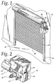
- a fire door operator embodying the present invention is generally shown therein and identified by reference numeral 10.
- the fire door operator has a DC solenoid 632 coupled to be controlled by a speed sensor 626 for detecting the descent speed of a fire door 20.
- An electronic control circuit 642 is connected to the speed sensor 626 and to the solenoid 632.
- Jackshaft driven fire door 20 includes a rolling door curtain 22 including a plurality of interconnected, pivotal slats.
- a pair of vertical guides 24 guide the vertical movement of the slats inside the guides to a first or open position and to a second or closed position.
- fire door 20 is in an open condition.
- the top of curtain 22 is fixed to a horizontally rotatable door shaft 26.
- Fire door operator 10 is coupled to door shaft 26 for winding and unwinding curtain 22 around door shaft 26 to respectively open and close the fire door 20.
- the door shaft 26 is enclosed in a housing 28, which is sized to hold the curtain in the fully open position.
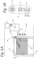
- FIG. 1A Additional features of the fire door operator of Figure 1 are shown in Figure 1A. From this view can be seen an independent alarm system (or smoke detector) 7 which is coupled electrically to a control panel 8.
- Control panel 8 also has a battery backup for operating the fire door operator in the event of a power failure.
- motor unit 12 is preferably a one half horsepower AC motor.
- Junction box 9 provides AC power to operate unit 12 as well as for charging the battery backup system in control panel 8.
- Key station 6 includes speaker 3 for providing audible warnings in the event of an alarm, reset key switch 4 for testing the system simulating an alarm condition and push button station 5 for controlling normal operation of the door 20.
- Control station 5 includes three buttons: open, close and stop. Warning lights 2 are provided in the guide rails for warning persons of imminent door closure.
- Reversible safety edge 13 stops and reverses the door in the event an obstruction is detected.
- an IR light system or other obstruction system can be installed for detecting obstacles in the path of the door. Further details of the operation of the fire door system are described with reference to Figures 5A-5C.
- fire door operator 10 may be mounted to the wall in a vertical position (with the motor 12 shown at the top) .
- fire door operator 10 may be mounted to housing 28 as shown in Figure 7C via a bracket 72. Horizontal mounting to housing 28 is also possible.
- FIG 2 shows a perspective view of fire door operator 10 in Figure 1.
- Motor 12 drives input shaft 14, which is coupled to output shaft 16 through a gear reduction system (not shown) .
- Electrical control box 17 houses the programmable logic board which controls the descent speed of the fire door 20 in the event of an AC power outage.
- Brake and solenoid 201 are coupled to motor 12, which is coupled to linear gear reducer 203.
- the electrical box 17 includes audio annunciator 201, limit switches 205, RPM sensor 206, speakers and strobe lights 207 and control board 210.
- Transformer and rectification module 208 provides the main power to the operator 10.
- battery bank 209 is shown installed in electrical box 17.
- the battery backup could be a separate wall mounted box.
- Accessories available are the test station 211, IR emitter/receiver 212 and reversible edge detector 213.
- Figure 6 is an exploded perspective view of the fire door operator of Figure 2.
- Dual sprocket 625 is attached to the end of output shaft 648.
- Input shaft 622 fits into opening 649 of cover 651.
- the brake box houses the brake solenoid 632, and brake assembly 650.
- Brake solenoid 632 engages and disengages brake assembly 650 comprising brake pressure plate 604, brake release lever 606 and brake pads 640.
- brake assembly 650 acts on output shaft 648 to reduce its rotational speed.
- Electrical box 19 includes cover 608 and enclosure 609 and houses transformer 631, batteries 641, programmable logic controller board 642, contactor 601 and contact blocks 636.
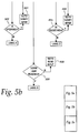
- Step 500 Operation of the programmable logic controller is shown in the flow chart of Figures 5A, 5B and 5C.
- the controller starts operation at Step 500, after power is applied to the system.
- Step 501 the controller goes through an initialization step in which the brake is on (the solenoid is engaged), all input registers are cleared (close, stop and open) and the obstruction counter is cleared.
- Step 502 the controller reads all new input signals and compares them (Step 503) with any previous input signals. It there are no changes, the controller branches to Step 504 where the system goes to a monitor condition.
- Step 505 the controller checks for an active alarm. If the alarm is not active, it checks for brake (Step 506) then returns to Step 502.
- Step 505 if the alarm is on, the controller continues to Step 508. If the alarm is on, i.e. an alarm signal is received form the external alarm system or smoke detector, the controller activates the audio/visual warning system.
- the audio/visual warning in the form of buzzers or recorded messages and flashing lights lasts for the period of time pre-selected by the user through one of the dip switches 19. Stop and Open are cleared and Close is enabled.
- Step 517 if the output of the Stop gate is high, in Step 521, the controller branches back to Step 502. If the output of Stop is low, it continues to step 522 to check is the output of Open is high. If Open is high, in Step 521, the controller branches back to Step 507, Verify Input. If Open is low, the controller continues to Step 527 to check is if the down limit has been reached. If the down limit has not been reached, the controller checks at Step 530 for an obstruction. If there is no obstruction, the controller releases the brake in Step 538 and detects the descent speed. In Step 539, the controller measures the descent speed of the door. If the speed is within the predetermined limits, it branches back to Step 513.
- Step 543 the controller engages the brake for a specific time determined by the speed of the door; the faster the door speed, the longer the engagement time. At the end of the time period, the controller releases the brake at Step 548 and then branches back to Step 513.
- Step 536 the controller increments the instruction counter. If the counter is greater than 3 (Step 540), the controller sets the counter to 4 (Step 542), clears Close and Open and Sets Stop (Step 544) then branches at Step 547 to Step 507, Verify Input. If the counter is less than 3, the controller branches to Step 551 where it clears Close and Stop and Sets Open. Then at Step 552, the controller branches back to Step 507, Verify Input.
- the controller has been programmed to allow the door to descend and check for the obstruction three times. Each time, the door reverses and opens. On the fourth time, the door is set to Stop just above the obstruction. The number of times the controller checks for an obstruction can be varied depending on user requirements.
- Step 527 if the down limit has been reached (the door has reached the floor or other closed location), the controller branches to Step 528 where it deactivates the audio/visual warning system and releases the brake.
- Step 531 the controller clears all inputs and clears all counters.
- Step 534 the controller returns to Step 502, Read Inputs.
- Step 507 if the input has changed, the controller branches to Step 507, where it verifies the input.
- a valid input is determined if all of the commands (Stop, Close, Open and None) are low or only one of the four is high. All other inputs are invalid.
- Step 501 if the input is not valid, the controller branches to Step 509 and uses the last valid input as the new input and returns to Step 507. If the new input is valid at Step 510, the controller continues to Step 511 to check is AC power is available. If AC power is available, it branches to the Stop, Open, Close or None command. If AC power is not active, at Step 512, the controller clears Open.
- the Close routine at Step 513 has already been described above.
- the None routine at Step 516 just sends (Step 520) the controller back to Read Input, Step 502.
- Step 514 begins the Stop routine (after a user selects the Stop command at button commands 5.
- Step 518 the motor power is disengaged and the brake is applied. If the down limit has not been reached, the controller branches at Step 525 to Step 502 Read Input, leaving the door stopped at its current location. If the down limit has been reached (Step 526), the controller continues to Step 528 where the audio/visual warnings are deactivated (they would not be activated in a normal Stop command) and the brake is released. Then in Step 531, all inputs and counters are cleared. And in Step 534 the controller returns to Step 502, Read Input.
- Step 515 begins the Open routine. First the controller checks for Stop high. If yes, it branches at Step 523 to Step 507 to Verify Input. Then it checks for Close high. If yes, it branches at Step 523 to Step 507, Verify Input. If not, the controller continues to Step 541 and checks for the up limit. If the up limit has not been reached, at Step 545, the controller engages the motor. To enable the motor to develop sufficient power to move the door, a time delay is programmed into the system. At Step 546, after the expiration of the time delay, the brake is released and the door begins moving up. The controller then branches at Step 550 back to Step 515, Open. If the up limit has been reached at Step 541, the controller engages the brake at Step 529, disengages motor power at Step 532, clears all inputs and counters at Step 531 and branches at Step 534 to Read Input, Step 502.
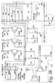
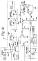
- programmable logic board includes microcontroller 301, which may be a Zilog brand Z86E40 with 4K of ROM on board. External connections for some of the optional controls are made through terminal block 302. Inputs for IR eyes (Ir_IN+ and IR_- at pins 1 and 2), 5V Logic Input1 at pin 3. The B2 button control switches are also wired into block 302: Reverse at pin 6, Key-Reset at pin 6, Open at pin 8, Close at pin 9, Stop at pin 10. The external alarm system is input at pins 10 and 11.
- IR circuit 310 which applies signal IR_IN to pin P30 of microcontroller 301 and is also coupled to timing circuit 311. Open, Close and Stop signals are applied to pins P13, P14, P15 respectively of microcontroller 301. Additionally, LED lights 303, 304, 305 respectively are lit when the respective button is pushed.
- External limit switch circuitry is applied to terminal block 306.
- the Up and Down limits are input from terminals 1 and 3, respectively of block 306, then applied to pins P11 and P12 of microcontroller 301.
- Lights 307, 308 and 309 are lit when the Up, Down or Aux switches have been met.
- Buzzer circuit 313 emits a warning sound when energized by pin P34 of microcontroller 301 after the battery test circuitry 410 indicates a low battery.
- An external alarm signal from pin 11 of block 302 is applied to P17 of microcontroller. During an alarm, the various counts are stored in EEPROM 315.
- the output of the RPM sensor circuit 314, SPEED_IN, is applied to pin P31 of microcontroller 301.
- the output of RPM Board 316 is applied to RPM connector 317.
- RPM board 316 measures the speed of the limit sprocket on the output shaft.
- Brake signal inputs from microcontroller 301 are applied via BRAKE to circuit 411 which enables and disabled the solenoid, which then engages and disengages the brake.
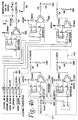
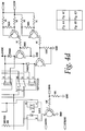
- circuit 401 shows the external electrical connections for the motor, brake solenoid and transformer.
- Circuit 402 takes AC power and rectifies it to DC. Other audio, visual and auxiliary connections can also be made.
- a specific example of a preferred fire door operator includes a removable, continuous duty AC motor with overload protection and the following specifications.
- Half and one horsepower models operating at 115 volts (single phase), 230 volts (single and three phase) and 460 volts (three phase) at 31 revolutions per minute are generally suitable for use with the fire doors contemplated.
- the output shaft to limit shaft preferred ration is 1 to 2.11 with a maximum limit shaft revolutions of 70.
- Sprocket sizes are 501B19 and 50B19 for the half and one horsepower motors, respectively, both with square key.
- Door sprocket is 50B32.
- Output shaft is 3/4 inch and 1 1/4 inch for the half and one horsepower motors, respectively.
- Mounting is horizontal.
- the brake solenoid can be a DC solenoid rated at 24 volts DC or an AC solenoid rated at the line voltage used. Minimum brake away torque is 144 inch pounds. The brake is rated at 720 inch pounds and 1440 inch pounds for the half and one horsepower motors, respectively.
- a preferred power source for the system is 24 volts AC at 6 amperes with a 24 volt DC battery back up.
- the battery back up system can be a short life system which includes two 12 volt .8 ampere hour lead acid batteries (UL listed and flame retardant).
- Another battery back up system with extended life includes two 12 volt 7 ampere hour lead acid batteries (UL listed and flame retardant). The batteries are automatically charged whenever there is AC power present except when the unit is in the load test mode.
- the programmable logic controller includes preferably six 24 volt DC 30 ampere NO (normally open) relays for external and internal devices. Two relays are used for battery test and DC solenoid control circuits. Two relays are used to control the audio and visual warning systems.
- two DIP switches are provided to enable the user to select the time to close. Delay times of 10, 20, 30 and 60 seconds are available.
- Door speed is monitored (during loss of AC power) by a slotted optical sensor connected via a 5 pin plug-in connector.
- the optical sensor detects the rotational speed of a sprocket on the limit shaft.
- Normal speed is preferably 63 rpm.
- Excessive speed, maximum allowed descent speed, is defined as 70 rpm.
- the door speed control mechanism is only activated when the door is closing. If door speed exceeds 70 rpm, the brake is engaged in inverse proportion to the door instantaneous speed. The faster the door is traveling, the higher the duty cycle of the brake.
- the normal speed and excessive or maximum speed are software configurable.
- Limit switches are used to set the maximum open and close travel for the door.
- Limit switches (Close, Open and Auxiliary) are NC (normally closed) switches and connected to the control board via a 4 pin plug-in connector. LED indicators are provided for each limit switch. If both Close and Open switches are activated, the microprocessor is reset.
- buttons are NO (normally open) momentary switches. Stop is a NC momentary switch. LED indicators are also provided for each switch. If more than one button is pressed at the same time, the controller ignores the input (equivalent to pressing no buttons).
- Either the reverse edge or an IR system may be installed for obstruction detection.
- the activation of the reverse edge is equivalent to interrupting the IR eye's signal; both conditions indicate an obstruction exists.
- the reverse edge is a NO switch. It is disabled if the auxiliary limit switch is active.
- the IR eye must be enabled by activating the fourth DIP switch on the programmable logic controller. If the IR eye is not installed, the DIP switch must be disabled.
- Key reset is a momentary NO switch. If the key reset switch is activated for at least six seconds, the unit will enter the alarm active mode. The unit will exit the alarm active mode if the Close limit is reached or two minutes have elapsed, whichever occurs first.
- the external alarm system or smoke detector is connected to the controller's circuit board on screw-type terminals. Dip switch number 3 must be set to specify the alarm contact of NO or NC.
- the warning system may include a speech board with speakers, which plays a recorded message warning of the door closure and a strobe assembly which flashes strobe lights prior to door closure.
- the fire door operator includes a switch or other control to enable the door to be opened and closed normally.
- a typical normal open/close door control includes a three button station (open, close, stop) and wiring direct to the AC line voltage.
- Another one button key switch is used for testing the system. If the one button key switch is held for six seconds, it causes the alarm sequence to be activated for a two minute test period or until the down limit is reached.
- a reversing edge if activated when the door is traveling down, causes the door to reverse to the up limit. If the edge is activated when the door is traveling up, the door stops.
- the brake is powered by a DC solenoid. If the DC solenoid is on continually, it keeps the brake engaged.
- the brake is disengaged when the door is in motion.
- the solenoid has a 12 hour battery back up, providing the batteries are fully charged.
- the battery back up is load tested once every thirty days. If the battery needs replacement, a unit mounted buzzer or warning light will sound or light once a minute for a three second duration.
- Alarm Condition with AC Power Upon receipt of an alarm condition (AC power present), the unit activates the audio and visual warning relays, if the door is not already closed.
- the alarm input sense NO or NC
- the audio/visual warning system play time is also user set by a dip switch to 10, 20, 30 or 60 seconds.
- the door reverses again to the full open limit an resets the audio/visual relays for the set delay time and then closes the door.
- the system stops the door on the obstruction, then releases the brake after 2 seconds. If the obstruction is later removed, the unit performs a controlled drop of the door, not powered by the motor, using the internal inertia of the gear reduction system to slow the fall. If the reversing edge is activated while traveling up, the door will stop, then reactivate the alarm close sequence. Once the down limit is reached, the audio/visual relays are deactivated [do the strobe lights stay on with the relay deactivated?]. The fire door controller will respond to the three button switch commands as a temporary override, but if left open, the system will reactivate the warning relays for the set time delay and attempt to close the door.
- the unit releases the brake.
- the RPM sensor monitors the door's descent so that door speed does not exceed a predetermined maximum speed of 9 inches per second. If the door speed exceed 9 in/sec, the DC solenoid engages the brake. The brake stays engaged until the door speed slows to a predetermined minimum speed of 6 in/sec.
- the stop button is functional during door descent to halt travel (provided there is sufficient battery power). During door closure, an obstruction will cause the DC solenoid to engage the brake. A close command is needed to restart door closure after the obstruction is removed. If the AC power outage persists, before the battery system discharges totally, the fire door operator will play the audio/visual warning as described above, however, stop is not functional in this case. If the battery is at full charge, the door will close with approximately 10 close cycles possible.
- the audio/visual warning system is activated for the user-preset delay time. After the expiration of the time-to-close delay period (10, 20, 30 or 60 seconds), the door is released to fall via the DC solenoid brake control. If the door speed exceeds 9 in/sec, the brake is engaged until the door speed falls to 6 in/sec. If an obstruction is sensed during door closure, the brake engages and holds the door the preset time-to-close delay period. After holding the door for the delay period, the brake is released, stopping the door at the obstruction. Once the door activates the down limit, the audio/visual warning system is disabled.
- the time-to-close delay period 10, 20, 30 or 60 seconds
- the fire door operator unit performs a battery test automatically every thirty days.
- the first load test occurs thirty days after initial powerup.
- the test involves placing the battery under a set load for a predetermined duration, preferably one hour plus or minus five minutes, to establish that it can hold the appropriate charge and operate the door in the event of an AC power failure and alarm condition.
- the battery serves as the sole power source for the brake solenoid for normal operation. If the battery discharges more than a predetermined amount, say 22.2 volts plus or minus .5 volts, during the test cycle, a low battery audio or visual warning is activated.
- the audio warning is from a buzzer, which emits a tone at 2 kiloHertz, which sounds for three seconds, once a minute, until the battery is replaced.
- the unit will consider the battery has been changed if both AC and DC power is removed or both the Open and Close limit switches are pressed. If the door is in the close limit, the brake solenoid will be engaged during the load-test mode.
- Exhibit A Software Listing . Attached hereto as Exhibit A is a source code listing for software used to control a programmable logic controller as described above.
Landscapes
- Engineering & Computer Science (AREA)
- Structural Engineering (AREA)
- Architecture (AREA)
- Civil Engineering (AREA)
- Power-Operated Mechanisms For Wings (AREA)
- Operating, Guiding And Securing Of Roll- Type Closing Members (AREA)
Abstract
Description
- This invention relates to fire door operators, and more particularly, to a fire door operator having an integrated electronically descent control device.
- Commercial doors come in a variety of configurations: rolling steel (jackshaft driven), overhead sectional (trolley driven), store front grilles (jackshaft driven), fire doors (jackshaft driven) and so on. A fire door is a specially designed commercial door which is placed in strategic locations throughout such places as factories, hospitals and schools to prevent the spread of fire through a building. In the event of a fire, the fire door closes automatically, sealing off protected areas and preventing further spread of the fire.
- The most basic version of a fire door system is a fire door coupled to a door sprocket. The sprocket includes a sprocket assembly having a fusible link that normally engages a sprocket to hold the door open. In the event of a fire, when the sprocket assembly reaches a critical temperature, the link softens or melts and releases the sprocket. The door springs to close and begins to descend in the downward direction. U.S. Patent No. 4,147,197 to Bailey et al. describes a fire door with only a fusible link for enabling closure.
- A controlled descent mechanism usually prevents the door from rapidly running uncontrolled into the floor due to acceleration from gravity. Frequently, the controlled descent mechanism is a mechanical assembly, such as a viscous clutch or governor, that prevents the door from exceeding a maximum or runaway speed. An example of a fire door system having an integrated viscous clutch assembly can be found in U.S. Patent No. 5,203,392 to Shea. Shea discloses a mechanism for controlling the raising and lowering of a fire door in which a pneumatically or hydraulically operated governor is mounted on an input shaft for limiting its rotational speed before it drives the speed reduction gearing driving the output shaft.
- In addition to being operated as a fire door, some fire doors need to be operated as regular commercial doors, requiring opening and closing through a more conventional door opener system. Commercial door openers typically include a motor, a gear reduction system and an electronic control package for automatically opening and closing the door. The single operation system of many fire doors, in which the fusible link must be replaced after closing, is not suitable for such dual use.
- More importantly, fire doors must be tied into the building smoke and fire alarm systems. In the event of a fire, smoke alarms can provide an earlier indication that the fire door should be closed than a purely mechanical system. In a purely mechanical system, the ambient temperature must reach a very high level to melt the fusible link before the door descends. In a fire door system connected to a smoke or fire alarm system, the fire door can be programmed to descend upon receipt of a fire alarm signal, before melting of the fusible link.
- Many fire door openers are powered by AC motors. AC motors are generally lower in cost because of their higher use than DC motors. Additionally, use of an AC motor means the opener can be driven by the line voltage without any expensive DC rectification or conditioning circuitry. The major disadvantage of an AC motor, however, is they cannot drive the system in the event of a power outage. Also, the AC brake solenoid in the reverse brake system, releases in a power outage, causing the door to drop when there is no alarm condition. Such AC motor systems are generally used in applications where the normal condition of the door is closed (normally closed or NC).
- In situations where the fire door is normally opened, or remains open for significant periods of time, some fire door operators are powered by a DC motor with battery backup. If the door needs to be opened or closed during the AC power outage, the operator can be operated with the battery backup. However, DC motor systems are more expensive than AC motor systems and, in the event of a failure of the battery backup system, the unit still requires a controlled descent device, if it has a fail safe brake.
- U.S. Patent No. 5,245,879 to McKeon describes a fail-safe fire door release mechanism having automatic reset. Fail-safe operation, in the industry, means the fire door will close in the absence of power, which frequently precedes a fire. McKeon is also concerned with having a fire door that can be automatically reset in the event of a power outage. McKeon's fail-safe mechanism includes a solenoid for activating a brake. In the absence of power, the solenoid is open and disengages the brake; in the presence of power, the brake is closed and engages the brake. Thus, when power is lost (whether or not there is a fire alarm), the brake is released allowing the door to close. Door descent speed is controlled by the governor arrangement described in the Shea patent. While McKeon provides for fail-safe operation, the door always closes during a power outage.
- There is a need for a fire door operator which can be driven by a low cost AC motor during normal door operation. There is also a need for a fire door operator which can reliably close the door during an alarm condition during a power outage. There is a need for a fire door operator which does not inadvertently release the door during a power outage unless there is a fire or an alarm condition; There is also a need for a fire door opener which controls the descent of the door electronically, without the added cost of an expensive viscous clutch. There is a further need for a fire door which is user configurable for alarm contact type, descent speed and time-to-close delay.
- To achieve the foregoing and other objects, a fire door operator embodying to the present invention includes a DC brake solenoid coupled to an AC motor drive system with an inline gear reducer. If AC power is lost, the brake can be controlled by an electronically controlled descent device and the battery backup power. If the brake is disengaged, the door will drop by overcoming the internal inertia and friction in the inline gear reducer. More particularly, an electronically controlled descent device for controlling the speed of descent of a fire door in response to a close command includes a DC solenoid which engages and disengages the brake holding the fire door. A sensor detects the descent speed of the fire door as it drops. An electronic controller, responsive to the speed sensor, selectively disables the DC solenoid when the descent speed reaches a predetermined maximum speed and enables the DC solenoid when the descent speed reaches a predetermined minimum speed. The operator can be operated using either normal DC solenoid logic (a high signal releases the brake) or fail safe logic (a low signal releases the brake).
- A method for electronically controlling the descent speed of a fire door without AC power or motor control is also described. Without AC power, the unit electronically releases a DC solenoid brake. The weight and spring tension of the door cause the door to descend. Speed of descent is controlled electronically by measuring the speed of the output sprocket of the drive shaft of the fire door and electrically modulating the brake engagement. An electronic control circuit, which operates on the DC battery backup power selectively enables and disables the DC solenoid based on detected door speed. If the fire door closing or descent speed exceeds a predetermined threshold, the electronic control circuit enables the DC solenoid, which engages the brake. The brake then slows the fire door. As fire door speed decreases, when it reaches a predetermined minimum speed, the electronic control circuit disables the DC solenoid and the brake is released. The electronic control circuit continues to modulate the brake engagement and disengagement until the fire door reaches its closed or final position.
- Since proper maintenance requires load testing and battery charging of the battery backup system, an integrated means to monitor, charge and test the batteries is provided. When batteries are low and in need of replacement, an audible or light warning may also be provided.
- The fire door operator also includes circuitry such as simple switch or jumper settings which enable the user to make field selections, depending on the type of door and external alarm system available, to control the type of alarm contact, maximum door descent speed, and time-to-close delay. For example, since the alarm system is independent of the fire door operator unit, the alarm contact type depends on the nature of the alarm system output relay. Some doors are normally open; others are normally closed. When there is an alarm condition present, the alarm system changes the state of its NO (normally open) or NC (normally closed) contact.
- Preferably, the door should not exceed a predetermined maximum speed when it is descending without AC power. The maximum speed allowed varies, depending on door type, reduction sprockets and other factors. To enable user selection of the maximum DC descent speed, field selectable switch or jumper settings may be provided.
- The timer to close is defined as the time delay between the time when the unit first receives an alarm condition and when the unit starts to close the door. The time delay is used, often in combination with audible and visual warnings of imminent door closure, to enable users to exit the area to be shut off when the door closes. Field selectable switch or jumper settings may be provided to enable changing the time-to-close delay.
-
- Figure 1 is a perspective view of a rolling fire door system having a fire door and a fire door operator, the fire door operator embodies the present invention;
- Figure 1A is a front view of the fire door and fire door operator of Figure 1;
- Figure 2 is a perspective view of the fire door operator shown in Figure 1;
- Figure 2A is a block diagram of the elements of the fire door operator shown in Figure 2;
- Figures 3 and 4 are circuit diagrams of the electrical connections to a programmable logic board for a fire door operator shown in Figure 1;
- Figures 5A, 5B and 5C are a flow chart of a logic control board for use in a fire door operator shown in Figure 1;
- Figure 6 is an exploded perspective view of the fire door operator of Figure 2;
- Figure 7A is a perspective view of a fire door operator shown in Figure 1 and mounted to wall;
- Figure 7B is a front view of the fire door operator shown in Figure 7A; and
- Figure 7C is a perspective view of a fire door operator shown in Figure 1 and connected to a fire door curtain housing.
-
- Referring now to the drawings and especially to Figures 1, 2,
1A 2A and 6, a fire door operator embodying the present invention is generally shown therein and identified byreference numeral 10. The fire door operator has aDC solenoid 632 coupled to be controlled by aspeed sensor 626 for detecting the descent speed of afire door 20. Anelectronic control circuit 642 is connected to thespeed sensor 626 and to thesolenoid 632. - Jackshaft driven
fire door 20 includes a rollingdoor curtain 22 including a plurality of interconnected, pivotal slats. A pair ofvertical guides 24 guide the vertical movement of the slats inside the guides to a first or open position and to a second or closed position. As shown in Figure 1,fire door 20 is in an open condition. The top ofcurtain 22 is fixed to a horizontallyrotatable door shaft 26.Fire door operator 10 is coupled todoor shaft 26 for winding and unwindingcurtain 22 arounddoor shaft 26 to respectively open and close thefire door 20. Typically, thedoor shaft 26 is enclosed in ahousing 28, which is sized to hold the curtain in the fully open position. - Additional features of the fire door operator of Figure 1 are shown in Figure 1A. From this view can be seen an independent alarm system (or smoke detector) 7 which is coupled electrically to a
control panel 8.Control panel 8 also has a battery backup for operating the fire door operator in the event of a power failure. In this example,motor unit 12 is preferably a one half horsepower AC motor.Junction box 9 provides AC power to operateunit 12 as well as for charging the battery backup system incontrol panel 8.Key station 6 includesspeaker 3 for providing audible warnings in the event of an alarm, resetkey switch 4 for testing the system simulating an alarm condition and pushbutton station 5 for controlling normal operation of thedoor 20.Control station 5 includes three buttons: open, close and stop.Warning lights 2 are provided in the guide rails for warning persons of imminent door closure. Many types of obstruction detection systems are available to prevent closure on an obstruction.Reversible safety edge 13 stops and reverses the door in the event an obstruction is detected. In the alternative, an IR light system or other obstruction system can be installed for detecting obstacles in the path of the door. Further details of the operation of the fire door system are described with reference to Figures 5A-5C. - As shown in Figures 7A and 7B,
fire door operator 10 may be mounted to the wall in a vertical position (with themotor 12 shown at the top) . Alternatively,fire door operator 10 may be mounted tohousing 28 as shown in Figure 7C via abracket 72. Horizontal mounting tohousing 28 is also possible. - Figure 2 shows a perspective view of
fire door operator 10 in Figure 1.Motor 12 drivesinput shaft 14, which is coupled tooutput shaft 16 through a gear reduction system (not shown) .Electrical control box 17 houses the programmable logic board which controls the descent speed of thefire door 20 in the event of an AC power outage. Referring to Figure 2A, a block diagram of thefire door operator 10 and optional systems is shown. Brake andsolenoid 201 are coupled tomotor 12, which is coupled tolinear gear reducer 203. Theelectrical box 17 includesaudio annunciator 201,limit switches 205,RPM sensor 206, speakers andstrobe lights 207 andcontrol board 210. Transformer andrectification module 208 provides the main power to theoperator 10. In this embodiment,battery bank 209 is shown installed inelectrical box 17. Optionally, the battery backup could be a separate wall mounted box. Accessories available are thetest station 211, IR emitter/receiver 212 andreversible edge detector 213. - Figure 6 is an exploded perspective view of the fire door operator of Figure 2.
Dual sprocket 625 is attached to the end ofoutput shaft 648.Input shaft 622 fits into opening 649 ofcover 651. The brake box houses thebrake solenoid 632, andbrake assembly 650.Brake solenoid 632 engages and disengagesbrake assembly 650 comprisingbrake pressure plate 604,brake release lever 606 andbrake pads 640. Upon enablement of the brake solenoid,brake assembly 650 acts onoutput shaft 648 to reduce its rotational speed.Electrical box 19 includescover 608 andenclosure 609 and housestransformer 631,batteries 641, programmablelogic controller board 642,contactor 601 and contact blocks 636. - Operation of the programmable logic controller is shown in the flow chart of Figures 5A, 5B and 5C. The controller starts operation at
Step 500, after power is applied to the system. InStep 501, the controller goes through an initialization step in which the brake is on (the solenoid is engaged), all input registers are cleared (close, stop and open) and the obstruction counter is cleared. InStep 502, the controller reads all new input signals and compares them (Step 503) with any previous input signals. It there are no changes, the controller branches to Step 504 where the system goes to a monitor condition. InStep 505, the controller checks for an active alarm. If the alarm is not active, it checks for brake (Step 506) then returns to Step 502. - Returning to Step 505, if the alarm is on, the controller continues to Step 508. If the alarm is on, i.e. an alarm signal is received form the external alarm system or smoke detector, the controller activates the audio/visual warning system. The audio/visual warning in the form of buzzers or recorded messages and flashing lights lasts for the period of time pre-selected by the user through one of the dip switches 19. Stop and Open are cleared and Close is enabled.
- The Close routine begins at
Step 513. InStep 517, if the output of the Stop gate is high, inStep 521, the controller branches back toStep 502. If the output of Stop is low, it continues to step 522 to check is the output of Open is high. If Open is high, inStep 521, the controller branches back toStep 507, Verify Input. If Open is low, the controller continues to Step 527 to check is if the down limit has been reached. If the down limit has not been reached, the controller checks atStep 530 for an obstruction. If there is no obstruction, the controller releases the brake inStep 538 and detects the descent speed. InStep 539, the controller measures the descent speed of the door. If the speed is within the predetermined limits, it branches back toStep 513. If the speed is not within the predetermined limits, it continues to Step 543. InStep 543, the controller engages the brake for a specific time determined by the speed of the door; the faster the door speed, the longer the engagement time. At the end of the time period, the controller releases the brake atStep 548 and then branches back toStep 513. - Returning to Step 530, if there is an obstruction, the controller branches to Step 536. In
Step 536, the controller increments the instruction counter. If the counter is greater than 3 (Step 540), the controller sets the counter to 4 (Step 542), clears Close and Open and Sets Stop (Step 544) then branches atStep 547 to Step 507, Verify Input. If the counter is less than 3, the controller branches to Step 551 where it clears Close and Stop and Sets Open. Then atStep 552, the controller branches back toStep 507, Verify Input. In the foregoing, the controller has been programmed to allow the door to descend and check for the obstruction three times. Each time, the door reverses and opens. On the fourth time, the door is set to Stop just above the obstruction. The number of times the controller checks for an obstruction can be varied depending on user requirements. - Returning to Step 527, if the down limit has been reached (the door has reached the floor or other closed location), the controller branches to Step 528 where it deactivates the audio/visual warning system and releases the brake. Next in
Step 531, the controller clears all inputs and clears all counters. InStep 534, the controller returns to Step 502, Read Inputs. - Returning to Step 503, if the input has changed, the controller branches to Step 507, where it verifies the input. A valid input is determined if all of the commands (Stop, Close, Open and None) are low or only one of the four is high. All other inputs are invalid. In
Step 501, if the input is not valid, the controller branches to Step 509 and uses the last valid input as the new input and returns to Step 507. If the new input is valid atStep 510, the controller continues to Step 511 to check is AC power is available. If AC power is available, it branches to the Stop, Open, Close or None command. If AC power is not active, atStep 512, the controller clears Open. - The Close routine at
Step 513 has already been described above. The None routine atStep 516 just sends (Step 520) the controller back to Read Input,Step 502. - Step 514 begins the Stop routine (after a user selects the Stop command at button commands 5. In
Step 518, the motor power is disengaged and the brake is applied. If the down limit has not been reached, the controller branches atStep 525 to Step 502 Read Input, leaving the door stopped at its current location. If the down limit has been reached (Step 526), the controller continues to Step 528 where the audio/visual warnings are deactivated (they would not be activated in a normal Stop command) and the brake is released. Then inStep 531, all inputs and counters are cleared. And inStep 534 the controller returns to Step 502, Read Input. - Step 515 begins the Open routine. First the controller checks for Stop high. If yes, it branches at
Step 523 to Step 507 to Verify Input. Then it checks for Close high. If yes, it branches atStep 523 to Step 507, Verify Input. If not, the controller continues to Step 541 and checks for the up limit. If the up limit has not been reached, atStep 545, the controller engages the motor. To enable the motor to develop sufficient power to move the door, a time delay is programmed into the system. AtStep 546, after the expiration of the time delay, the brake is released and the door begins moving up. The controller then branches atStep 550 back toStep 515, Open. If the up limit has been reached atStep 541, the controller engages the brake atStep 529, disengages motor power atStep 532, clears all inputs and counters atStep 531 and branches atStep 534 to Read Input,Step 502. - Operation of the fire door operator is controlled by a programmable logic board. Referring to Figure 3, programmable logic board includes
microcontroller 301, which may be a Zilog brand Z86E40 with 4K of ROM on board. External connections for some of the optional controls are made throughterminal block 302. Inputs for IR eyes (Ir_IN+ and IR_- atpins 1 and 2), 5V Logic Input1 atpin 3. The B2 button control switches are also wired into block 302: Reverse atpin 6, Key-Reset atpin 6, Open atpin 8, Close atpin 9, Stop atpin 10. The external alarm system is input atpins - The output of the external IR obstruction detector at
terminal block 302 is applied toIR circuit 310, which applies signal IR_IN to pin P30 ofmicrocontroller 301 and is also coupled totiming circuit 311. Open, Close and Stop signals are applied to pins P13, P14, P15 respectively ofmicrocontroller 301. Additionally, LED lights 303, 304, 305 respectively are lit when the respective button is pushed. - External limit switch circuitry is applied to
terminal block 306. The Up and Down limits are input fromterminals block 306, then applied to pins P11 and P12 ofmicrocontroller 301.Lights -
Buzzer circuit 313 emits a warning sound when energized by pin P34 ofmicrocontroller 301 after thebattery test circuitry 410 indicates a low battery. - An external alarm signal from
pin 11 ofblock 302 is applied to P17 of microcontroller. During an alarm, the various counts are stored inEEPROM 315. The output of theRPM sensor circuit 314, SPEED_IN, is applied to pin P31 ofmicrocontroller 301. The output of RPM Board 316 is applied to RPM connector 317. RPM board 316 measures the speed of the limit sprocket on the output shaft. Brake signal inputs frommicrocontroller 301 are applied via BRAKE tocircuit 411 which enables and disabled the solenoid, which then engages and disengages the brake. - Referring to Figure 4, circuit 401 shows the external electrical connections for the motor, brake solenoid and transformer.
Circuit 402 takes AC power and rectifies it to DC. Other audio, visual and auxiliary connections can also be made. - A specific example of a preferred fire door operator includes a removable, continuous duty AC motor with overload protection and the following specifications. Half and one horsepower models operating at 115 volts (single phase), 230 volts (single and three phase) and 460 volts (three phase) at 31 revolutions per minute are generally suitable for use with the fire doors contemplated. The output shaft to limit shaft preferred ration is 1 to 2.11 with a maximum limit shaft revolutions of 70.
- A linear gear reducer with an output torque of 800 inches/pound for the one half horsepower motor and 1300. inches/pound for the one horsepower motor. Maximum overload is 400 pounds at one inch for the half horsepower motor, and 800 pounds at one inch for the one horsepower motor. Sprocket sizes are 501B19 and 50B19 for the half and one horsepower motors, respectively, both with square key. Door sprocket is 50B32. Output shaft is 3/4 inch and 1 1/4 inch for the half and one horsepower motors, respectively. Mounting is horizontal. The brake solenoid can be a DC solenoid rated at 24 volts DC or an AC solenoid rated at the line voltage used. Minimum brake away torque is 144 inch pounds. The brake is rated at 720 inch pounds and 1440 inch pounds for the half and one horsepower motors, respectively.
- A preferred power source for the system is 24 volts AC at 6 amperes with a 24 volt DC battery back up. The battery back up system can be a short life system which includes two 12 volt .8 ampere hour lead acid batteries (UL listed and flame retardant). Another battery back up system with extended life includes two 12
volt 7 ampere hour lead acid batteries (UL listed and flame retardant). The batteries are automatically charged whenever there is AC power present except when the unit is in the load test mode. - Relay Control Specifications. The programmable logic controller includes preferably six 24
volt DC 30 ampere NO (normally open) relays for external and internal devices. Two relays are used for battery test and DC solenoid control circuits. Two relays are used to control the audio and visual warning systems. - Preferably, two DIP switches are provided to enable the user to select the time to close. Delay times of 10, 20, 30 and 60 seconds are available. A third DIP switch is provided to enable the user to select OPEN = NO Alarm mode or CLOSE = NC Alarm mode. A fourth DIP switch is provided to enable an IR obstruction detection system with OPEN = IR disabled and CLOSE = IR enabled.
- Descent Door Speed Control Specifications. Door speed is monitored (during loss of AC power) by a slotted optical sensor connected via a 5 pin plug-in connector. The optical sensor detects the rotational speed of a sprocket on the limit shaft. Normal speed is preferably 63 rpm. Excessive speed, maximum allowed descent speed, is defined as 70 rpm. The door speed control mechanism is only activated when the door is closing. If door speed exceeds 70 rpm, the brake is engaged in inverse proportion to the door instantaneous speed. The faster the door is traveling, the higher the duty cycle of the brake. The normal speed and excessive or maximum speed are software configurable.
- Limit Switch Specification. Limit switches are used to set the maximum open and close travel for the door. Limit switches (Close, Open and Auxiliary) are NC (normally closed) switches and connected to the control board via a 4 pin plug-in connector. LED indicators are provided for each limit switch. If both Close and Open switches are activated, the microprocessor is reset.
- B2 Switch Specification. The Open and Close buttons are NO (normally open) momentary switches. Stop is a NC momentary switch. LED indicators are also provided for each switch. If more than one button is pressed at the same time, the controller ignores the input (equivalent to pressing no buttons).
- Either the reverse edge or an IR system may be installed for obstruction detection. The activation of the reverse edge is equivalent to interrupting the IR eye's signal; both conditions indicate an obstruction exists. The reverse edge is a NO switch. It is disabled if the auxiliary limit switch is active. The IR eye must be enabled by activating the fourth DIP switch on the programmable logic controller. If the IR eye is not installed, the DIP switch must be disabled.
- Key Reset. Key reset is a momentary NO switch. If the key reset switch is activated for at least six seconds, the unit will enter the alarm active mode. The unit will exit the alarm active mode if the Close limit is reached or two minutes have elapsed, whichever occurs first.
- Alarm Mode. The external alarm system or smoke detector is connected to the controller's circuit board on screw-type terminals.
Dip switch number 3 must be set to specify the alarm contact of NO or NC. - The warning system may include a speech board with speakers, which plays a recorded message warning of the door closure and a strobe assembly which flashes strobe lights prior to door closure.
- Normal AC Operation: Preferably, the fire door operator includes a switch or other control to enable the door to be opened and closed normally. A typical normal open/close door control includes a three button station (open, close, stop) and wiring direct to the AC line voltage. Another one button key switch is used for testing the system. If the one button key switch is held for six seconds, it causes the alarm sequence to be activated for a two minute test period or until the down limit is reached. A reversing edge, if activated when the door is traveling down, causes the door to reverse to the up limit. If the edge is activated when the door is traveling up, the door stops. The brake is powered by a DC solenoid. If the DC solenoid is on continually, it keeps the brake engaged. The brake is disengaged when the door is in motion. The solenoid has a 12 hour battery back up, providing the batteries are fully charged. The battery back up is load tested once every thirty days. If the battery needs replacement, a unit mounted buzzer or warning light will sound or light once a minute for a three second duration.
- Alarm Condition with AC Power: Upon receipt of an alarm condition (AC power present), the unit activates the audio and visual warning relays, if the door is not already closed. The alarm input sense (NO or NC) is user set by means of a dip switch on the unit. The audio/visual warning system play time is also user set by a dip switch to 10, 20, 30 or 60 seconds. Once the warning relays have been activated for the set time, the door will be closed. The strobe light remains on until the door is successfully opened. In the event of an obstruction, the door will reverse to the full open limit. The fire door controller will then reactivate the audio/visual relays for the set delay time and then closes the door. If the obstruction remains in place, the door reverses again to the full open limit an resets the audio/visual relays for the set delay time and then closes the door. Upon the third attempt to close the door, the system stops the door on the obstruction, then releases the brake after 2 seconds. If the obstruction is later removed, the unit performs a controlled drop of the door, not powered by the motor, using the internal inertia of the gear reduction system to slow the fall. If the reversing edge is activated while traveling up, the door will stop, then reactivate the alarm close sequence. Once the down limit is reached, the audio/visual relays are deactivated [do the strobe lights stay on with the relay deactivated?]. The fire door controller will respond to the three button switch commands as a temporary override, but if left open, the system will reactivate the warning relays for the set time delay and attempt to close the door.
- Loss of AC and No Alarm: When AC power is lost and there is no alarm condition, the "AC Power" light is switched off, leaving only the "DC Power" light lit. The unit loses B2 wiring functionality when AC power is lost. The DC brake remains engaged, holding the door open for up to 12 hours (the life of the fully charged batteries) unless the door is in the close limit. In the battery backup mode, the unit will automatically close the door if 12 hours have passed or low battery is detected, whichever occurs first. The door will not open until AC power is returned and the battery is charged above the minimum level.
- If the close button is pressed, the unit releases the brake. The RPM sensor monitors the door's descent so that door speed does not exceed a predetermined maximum speed of 9 inches per second. If the door speed exceed 9 in/sec, the DC solenoid engages the brake. The brake stays engaged until the door speed slows to a predetermined minimum speed of 6 in/sec. The stop button is functional during door descent to halt travel (provided there is sufficient battery power). During door closure, an obstruction will cause the DC solenoid to engage the brake. A close command is needed to restart door closure after the obstruction is removed. If the AC power outage persists, before the battery system discharges totally, the fire door operator will play the audio/visual warning as described above, however, stop is not functional in this case. If the battery is at full charge, the door will close with approximately 10 close cycles possible.
- Battery Mode and Alarm Condition: If AC power is lost and the system is operating on the battery back up system, upon receiving an alarm input, the audio/visual warning system is activated for the user-preset delay time. After the expiration of the time-to-close delay period (10, 20, 30 or 60 seconds), the door is released to fall via the DC solenoid brake control. If the door speed exceeds 9 in/sec, the brake is engaged until the door speed falls to 6 in/sec. If an obstruction is sensed during door closure, the brake engages and holds the door the preset time-to-close delay period. After holding the door for the delay period, the brake is released, stopping the door at the obstruction. Once the door activates the down limit, the audio/visual warning system is disabled.
- Low Battery Condition: The fire door operator unit performs a battery test automatically every thirty days. The first load test occurs thirty days after initial powerup. The test involves placing the battery under a set load for a predetermined duration, preferably one hour plus or minus five minutes, to establish that it can hold the appropriate charge and operate the door in the event of an AC power failure and alarm condition. During this time, the battery serves as the sole power source for the brake solenoid for normal operation. If the battery discharges more than a predetermined amount, say 22.2 volts plus or minus .5 volts, during the test cycle, a low battery audio or visual warning is activated. The audio warning is from a buzzer, which emits a tone at 2 kiloHertz, which sounds for three seconds, once a minute, until the battery is replaced. The unit will consider the battery has been changed if both AC and DC power is removed or both the Open and Close limit switches are pressed. If the door is in the close limit, the brake solenoid will be engaged during the load-test mode.
- Software Listing. Attached hereto as Exhibit A is a source code listing for software used to control a programmable logic controller as described above.
- When the LMPLC board is first powered up, it will delay for 2 seconds to allow all inputs to stabilize. It will then engage the brake regardless of the door position. Then it reads the limit switch to determine the door position, if at down limit then the brake will disengage. The following charts describe the unit operation under various conditions. (O = Active; X = Inactive; NA = either active or inactive.)
-
- STOP
- O
- CLOSE
- O
- OPEN
- O
-
- CLOSE
- O
- OPEN
- X
- AUX.
- O
-
- REV.
- O
- IR* BLOCK
- NO
-
- STOP
- O
- CLOSE
- O
- OPEN
- O
-
- CLOSE
- O
- OPEN
- X
- AUX.
- O
-
- REV.
- O
- IR* BLOCK
- YES
-
- STOP
- O
- CLOSE
- O
- OPEN
- O
-
- CLOSE
- O
- OPEN
- X
- AUX.
- O
-
- REV.
- X
- IR* BLOCK
- O
-
- STOP
- O
- CLOSE
- O
- OPEN
- O
-
- CLOSE
- O
- OPEN
- N/A
- AUX.
- O
-
- REV.
- O
- IR* BLOCK
- O
-
- STOP
- O
- CLOSE
- O
- OPEN
- O
-
- CLOSE
- O
- OPEN
- N/A
- AUX.
- O
-
- REV.
- X
- IR* BLOCK
- O
-
- STOP
- O
- CLOSE
- O
- OPEN
- O
-
- CLOSE
- N/A
- OPEN
- O
- AUX.
- X
-
- REV.
- N/A
- IR* BLOCK
- N/A
-
- STOP
- O
- CLOSE
- O
- OPEN
- O
-
- CLOSE
- O
- OPEN
- O
- AUX.
- O
-
- REV.
- O
- IR* BLOCK
- O
-
- STOP
- O
- CLOSE
- O
- OPEN
- O
-
- CLOSE
- O
- OPEN
- O
- AUX.
- O
-
- REV.
- O
- IR* BLOCK
- O
-
- STOP
- O
- CLOSE
- O
- OPEN
- O
-
- CLOSE
- O
- OPEN
- O
- AUX.
- O
-
- REV.
- X
- IR* BLOCK
- O
-
- STOP
- O
- CLOSE
- O
- OPEN
- O
-
- CLOSE
- X
- OPEN
- O
- AUX.
- N/A
-
- REV.
- N/A
- IR* BLOCK
- N/A
-
- STOP
- O
- CLOSE
- O
- OPEN
- X
-
- CLOSE
- O
- OPEN
- X
- AUX.
- O
-
- REV.
- N/A
- IR* BLOCK
- N/A
-
- STOP
- O
- CLOSE
- O
- OPEN
- X
-
- CLOSE
- X
- OPEN
- O
- AUX.
- N/A
-
- REV.
- N/A
- IR* BLOCK
- N/A
-
- STOP
- O
- CLOSE
- O
- OPEN
- X
-
- CLOSE
- O
- OPEN
- O
- AUX.
- O
-
- REV.
- N/A
- IR* BLOCK
- N/A
-
- STOP
- O
- CLOSE
- O
- OPEN
- X
-
- CLOSE
- O
- OPEN
- O
- AUX.
- O
-
- REV.
- O
- IR* BLOCK
- O
-
- STOP
- O
- CLOSE
- X
- OPEN
- O
-
- CLOSE
- X
- OPEN
- O
- AUX.
- X
-
- REV.
- N//A
- IR* BLOCK
- N/A
-
- STOP
- O
- CLOSE
- X
- OPEN
- O
-
- CLOSE
- O
- OPEN
- X
- AUX.
- O
-
- REV.
- O
- IR* BLOC
- K O
-
- STOP
- O
- CLOSE
- X
- OPEN
- O
-
- CLOSE
- O
- OPEN
- X
- AUX.
- O
-
- REV.
- X
- IR* BLOCK
- N/A
-
- STOP
- O
- CLOSE
- X
- OPEN
- O
-
- CLOSE
- O
- OPEN
- O
- AUX.
- O
-
- REV.
- O
- IR* BLOCK
- O
-
- STOP
- O
- CLOSE
- X
- OPEN
- O
-
- CLOSE
- O
- OPEN
- O
- AUX.
- O
-
- REV.
- O
- IR* BLOCK
- O
-
- STOP
- X
- CLOSE
- O
- OPEN
- O
-
- CLOSE
- O
- OPEN
- X
- AUX.
- O
-
- REV.
- N/A
- IR* BLOCK
- N/A
-
- STOP
- X
- CLOSE
- O
- OPEN
- O
-
- CLOSE
- X
- OPEN
- O
- AUX.
- X
-
- REV.
- N/A
- IR* BLOCK
- N/A
-
- STOP
- X
- CLOSE
- O
- OPEN
- O
-
- CLOSE
- O
- OPEN
- O
- AUX.
- O
-
- REV.
- N/A
- IR* BLOCK
- N/A
-
- STOP
- O
- CLOSE
- O
- OPEN
- O
-
- CLOSE
- O
- OPEN
- X
- AUX.
- O
-
- REV.
- O
- IR* BLOCK
- NO
-
- STOP
- O
- CLOSE
- O
- OPEN
- O
-
- CLOSE
- O
- OPEN
- X
- AUX.
- O
-
- REV.
- O
- IR* BLOCK
- YES
-
- STOP
- O
- CLOSE
- O
- OPEN
- O
-
- CLOSE
- O
- OPEN
- X
- AUX.
- O
-
- REV.
- X
- IR* BLOCK
- O
-
- STOP
- O
- CLOSE
- O
- OPEN
- O
-
- CLOSE
- O
- OPEN
- N/A
- AUX.
- O
-
- REV.
- O
- IR* BLOCK
- O
-
- STOP
- O
- CLOSE
- O
- OPEN
- O
-
- CLOSE
- O
- OPEN
- N/A
- AUX.
- O
-
- REV.
- X
- IR* BLOCK
- O
-
- STOP
- O
- CLOSE
- O
- OPEN
- O
-
- CLOSE
- N/A
- OPEN
- O
- AUX.
- X
-
- REV.
- N/A
- IR* BLOCK
- N/A
-
- STOP
- O
- CLOSE
- O
- OPEN
- O
-
- CLOSE
- O
- OPEN
- O
- AUX.
- O
-
- REV.
- O
- IR* BLOCK
- O
-
- STOP
- O
- CLOSE
- O
- OPEN
- O
-
- CLOSE
- X
- OPEN
- O
- AUX.
- N/A
-
- REV.
- N/A
- IR* BLOCK
- N/A
-
- STOP
- O
- CLOSE
- O
- OPEN
- X
-
- CLOSE
- O
- OPEN
- X
- AUX.
- O
-
- REV.
- N/A
- IR* BLOCK
- N/A
-
- STOP
- O
- CLOSE
- O
- OPEN
- X
-
- CLOSE
- X
- OPEN
- O
- AUX.
- N/A
-
- REV.
- N/A
- IR* BLOCK
- N/A
-
- STOP
- O
- CLOSE
- O
- OPEN
- X
-
- CLOSE
- O
- OPEN
- O
- AUX.
- O
-
- REV.
- N/A
- IR* BLOCK
- N/A
-
- STOP
- O
- CLOSE
- O
- OPEN
- X
-
- CLOSE
- O
- OPEN
- O
- AUX.
- O
-
- REV.
- O
- IR* BLOCK
- O
-
- STOP
- O
- CLOSE
- X
- OPEN
- O
-
- CLOSE
- X
- OPEN
- O
- AUX.
- X
-
- REV.
- N/A
- IR* BLOCK
- N/A
-
- STOP
- O
- CLOSE
- X
- OPEN
- O
-
- CLOSE
- O
- OPEN
- X
- AUX.
- O
-
- REV.
- O
- IR* BLOCK
- O
-
- STOP
- O
- CLOSE
- X
- OPEN
- O
-
- CLOSE
- O
- OPEN
- X
- AUX.
- O
-
- REV.
- X
- IR* BLOCK
- N/A
-
- STOP
- O
- CLOSE
- X
- OPEN
- O
-
- CLOSE
- O
- OPEN
- O
- AUX.
- O
-
- REV.
- O
- IR* BLOCK
- O
-
- STOP
- X
- CLOSE
- O
- OPEN
- O
-
- CLOSE
- O
- OPEN
- X
- AUX.
- O
-
- REV.
- N/A
- IR* BLOCK
- N/A
-
- STOP
- X
- CLOSE
- O
- OPEN
- O
-
- CLOSE
- X
- OPEN
- O
- AUX.
- X
-
- REV.
- N/A
- IR* BLOCK
- N/A
-
- STOP
- X
- CLOSE
- O
- OPEN
- O
-
- CLOSE
- O
- OPEN
- O
- AUX.
- O
-
- REV.
- N/A
- IR* BLOCK
- N/A
-
- STOP
- O
- CLOSE
- O
- OPEN
- O
-
- CLOSE
- O
- OPEN
- X
- AUX.
- O
-
- REV.
- O
- IR*BLOCK
- NO
-
- STOP
- O
- CLOSE
- O
- OPEN
- O
-
- CLOSE
- O
- OPEN
- X
- AUX.
- O
-
- REV.
- O
- IR*BLOCK
- YES
-
- STOP
- O
- CLOSE
- O
- OPEN
- O
-
- CLOSE
- O
- OPEN
- X
- AUX.
- O
-
- REV.
- X
- IR*BLOCK
- O
-
- STOP
- O
- CLOSE
- O
- OPEN
- O
-
- CLOSE
- O
- OPEN
- N/A
- AUX.
- O
-
- REV.
- O
- IR*BLOCK
- O
-
- STOP
- O
- CLOSE
- O
- OPEN
- O
-
- CLOSE
- O
- OPEN
- N/A
- AUX.
- O
-
- REV.
- X
- IR*BLOCK
- O
-
- STOP
- O
- CLOSE
- O
- OPEN
- O
-
- CLOSE
- N/A
- OPEN
- O
- AUX.
- X
-
- REV.
- N/A
- IR*BLOCK
- N/A
-
- STOP
- O
- CLOSE
- O
- OPEN
- O
-
- CLOSE
- O
- OPEN
- O
- AUX.
- O
-
- REV.
- O
- IR*BLOCK
- O
-
- STOP
- O
- CLOSE
- O
- OPEN
- O
-
- CLOSE
- N/A
- OPEN
- O
- AUX.
- N/A
-
- REV.
- O
- IR*BLOCK
- O
-
- STOP
- O
- CLOSE
- O
- OPEN
- O
-
- CLOSE
- O
- OPEN
- O
- AUX.
- O
-
- REV.
- X
- IR*BLOCK
- O
-
- STOP
- O
- CLOSE
- O
- OPEN
- O
-
- CLOSE
- X
- OPEN
- O
- AUX.
- N/A
-
- REV.
- N/A
- IR*BLOCK
- N/A
-
- STOP
- O
- CLOSE
- O
- OPEN
- X
-
- CLOSE
- O
- OPEN
- X
- AUX.
- O
-
- REV.
- N/A
- IR*BLOCK
- N/A
-
- STOP
- O
- CLOSE
- O
- OPEN
- X
-
- CLOSE
- X
- OPEN
- O
- AUX.
- N/A
-
- REV.
- N/A
- IR*BLOCK
- N/A
-
- STOP
- O
- CLOSE
- O
- OPEN
- X
-
- CLOSE
- O
- OPEN
- O
- AUX.
- O
-
- REV.
- N/A
- IR*BLOCK
- N/A
-
- STOP
- O
- CLOSE
- O
- OPEN
- X
-
- CLOSE
- O
- OPEN
- O
- AUX.
- O
-
- REV.
- O
- IR*BLOCK
- O
-
- STOP
- O
- CLOSE
- X
- OPEN
- O
-
- CLOSE
- X
- OPEN
- O
- AUX.
- X
-
- REV.
- N/A
- IR*BLOCK
- N/A
-
- STOP
- O
- CLOSE
- X
- OPEN
- O
-
- CLOSE
- O
- OPEN
- X
- AUX.
- O
-
- REV.
- O
- IR*BLOCK
- O
-
- STOP
- O
- CLOSE
- X
- OPEN
- O
-
- CLOSE
- O
- OPEN
- X
- AUX.
- O
-
- REV.
- X
- IR*BLOCK
- N/A
-
- STOP
- O
- CLOSE
- X
- OPEN
- O
-
- CLOSE
- O
- OPEN
- O
- AUX.
- O
-
- REV.
- O
- IR*BLOCK
- O
-
- STOP
- O
- CLOSE
- X
- OPEN
- O
-
- CLOSE
- O
- OPEN
- O
- AUX.
- O
-
- REV.
- O
- IR*BLOCK
- O
-
- STOP
- X
- CLOSE
- O
- OPEN
- O
-
- CLOSE
- O
- OPEN
- X
- AUX.
- O
-
- REV.
- N/A
- IR*BLOCK
- N/A
-
- STOP
- X
- CLOSE
- O
- OPEN
- O
-
- CLOSE
- X
- OPEN
- O
- AUX.
- X
-
- REV.
- N/A
- IR*BLOCK
- N/A
-
- STOP
- X
- CLOSE
- O
- OPEN
- O
-
- CLOSE
- O
- OPEN
- O
- AUX.
- O
-
- REV.
- N/A
- IR*BLOCK
- N/A
-
- STOP
- O
- CLOSE
- O
- OPEN
- O
-
- CLOSE
- O
- OPEN
- X
- AUX.
- O
-
- REV.
- O
- IR*BLOCK
- NO
-
- STOP
- O
- CLOSE
- O
- OPEN
- O
-
- CLOSE
- O
- OPEN
- X
- AUX.
- O
-
- REV.
- O
- IR*BLOCK
- YES
-
- STOP
- O
- CLOSE
- O
- OPEN
- O
-
- CLOSE
- O
- OPEN
- X
- AUX.
- O
-
- REV.
- X
- IR*BLOCK
- O
-
- STOP
- O
- CLOSE
- O
- OPEN
- O
-
- CLOSE
- O
- OPEN
- N/A
- AUX.
- O
-
- REV.
- O
- IR*BLOCK
- O
-
- STOP
- O
- CLOSE
- O
- OPEN
- O
-
- CLOSE
- O
- OPEN
- N/A
- AUX.
- O
-
- REV.
- X
- IR*BLOCK
- O
-
- STOP
- O
- CLOSE
- O
- OPEN
- O
-
- CLOSE
- N/A
- OPEN
- O
- AUX.
- X
-
- REV.
- N/A
- IR*BLOCK
- N/A
-
- STOP
- O
- CLOSE
- O
- OPEN
- O
-
- CLOSE
- O
- OPEN
- O
- AUX.
- O
-
- REV.
- O
- IR*BLOCK
- O
-
- STOP
- O
- CLOSE
- O
- OPEN
- O
-
- CLOSE
- X
- OPEN
- O
- AUX.
- N/A
-
- REV.
- N/A
- IR*BLOCK
- N/A
-
- STOP
- O
- CLOSE
- O
- OPEN
- X
-
- CLOSE
- O
- OPEN
- X
- AUX.
- O
-
- REV.
- N/A
- IR*BLOCK
- N/A
-
- STOP
- O
- CLOSE
- O
- OPEN
- X
-
- CLOSE
- X
- OPEN
- O
- AUX.
- N/A
-
- REV.
- N/A
- IR*BLOCK
- N/A
-
- STOP
- O
- CLOSE
- O
- OPEN
- X
-
- CLOSE
- O
- OPEN
- O
- AUX.
- O
-
- REV.
- N/A
- IR*BLOCK
- N/A
-
- STOP
- O
- CLOSE
- O
- OPEN
- X
-
- CLOSE
- O
- OPEN
- O
- AUX.
- O
-
- REV.
- O
- IR*BLOCK
- O
-
- STOP
- O
- CLOSE
- X
- OPEN
- O
-
- CLOSE
- X
- OPEN
- O
- AUX.
- X
-
- REV.
- N/A
- IR*BLOCK
- N/A
-
- STOP
- O
- CLOSE
- X
- OPEN
- O
-
- CLOSE
- O
- OPEN
- X
- AUX.
- O
-
- REV.
- O
- IR*BLOCK
- O
-
- STOP
- O
- CLOSE
- X
- OPEN
- O
-
- CLOSE
- O
- OPEN
- X
- AUX.
- O
-
- REV.
- X
- IR*BLOCK
- N/A
-
- STOP
- O
- CLOSE
- X
- OPEN
- O
-
- CLOSE
- O
- OPEN
- O
- AUX.
- O
-
- REV.
- O
- IR*BLOCK
- O
-
- STOP
- X
- CLOSE
- O
- OPEN
- O
-
- CLOSE
- O
- OPEN
- X
- AUX.
- O
-
- REV.
- N/A
- IR*BLOCK
- N/A
-
- STOP
- X
- CLOSE
- O
- OPEN
- O
-
- CLOSE
- X
- OPEN
- O
- AUX.
- X
-
- REV.
- N/A
- IR*BLOCK
- N/A
-
- STOP
- X
- CLOSE
- O
- OPEN
- O
-
- CLOSE
- O
- OPEN
- O
- AUX.
- O
-
- REV.
- N/A
- IR*BLOCK
- N/A
- * IR is enabled by
DIP switch # 4. IR block is equivalent to REV switch is activated. - ** These conditions assume that the "timer to close" delay is not completed.
- *** These conditions assume that the delay timer is completed.
- While there has been illustrated and described a particular embodiment of the present invention, it will be appreciated that numerous changes and modifications will occur to those skilled in the art, and it is intended in the appended claims to cover all those changes and modifications which followed in the true spirit and scope of the present invention.
Description: Warning system is activated for the preset time then the door will automatically close.**
Description: Warning system is activated but the door will not start the close sequence.**
Description: Warning system as activated for the preset time then the door will automatically close.**
Description: Door is automatically closing after delay. The door will continue to close even if alarm becomes inactive if the automatic closing sequence is already started.***
Description: Door will reverse to full open unless it is on its third attempt then it stops with the brake released.***
Description: If the auxiliary switch is active then the reverse switch and IR eyes reading is ignored.***
Description: Delay timer is reset for the preset time then door will automatically close again.
Description: Door will open to limit then reset the delay timer.
Description: Door will stop. If obstruction occurs prior to opening sequence it must be removed before another obstruction can be used to stop the door while it's opening. Delay timer is reset to the preset time. Warning system active.
Description: Warning system is deactivated. Brake is disengaged unless battery is in "load-test" mode.***
Description: Door already at open limit, ignore open input command. Warning system is active.
Description: Door will open immediately. Once the door is off the close limit warning system will be activated.
Description: Door will open immediately. Warning system is active. Once door reaches open limit, the timer to close is reset.
Description: Delay for 1.2-1.8 seconds, then open the door.
Description: Ignore input command. Warning system is deactivated. Door is already at close limit.
Description: Door will immediately close. Warning system is active.
Description: Ignore input command. Cannot close door because of obstruction. Warning system is active.
Description: Door will close immediately. Warning system is active.
Description: Delay for 1.2-1.8 seconds, then close the door. Warning system is active.
Description: Nothing happens, door is already stopped at open limit. Warning system is active.
Description: Nothing happens, door is already stopped at close limit. Warning system is deactivated.
Description: Door stops immediately. Brake is engaged. Timer to close is reset. Warning system is active.
Description: Warning system is activated for the preset time then the door will automatically close.
Description: Warning system is activated but the door will not start the close sequence.**
Description: Warning system is activated but the door will not start the close sequence.**
Description: Door automatically closes after delay. The door will continue to close even if alarm becomes inactive if automatic closing sequence is already started.***
Description: Door will stop and the brake is engaged for 15 seconds then released.***
Description: If the auxiliary switch is active then the reverse switch and IR eyes reading is ignored.
Description: Delay timer is reset for the preset time then door will automatically close again.
Description: Warning system is deactivated. Brake is disengaged unless battery is in "load-test" mode.***
Description: Ignore open input command. Warning system is activated.
Description: Ignore open input command. Warning system is activated.
Description: Ignore open input command. Warning system is activated.
Description: Ignore open input command. Warning system is activated.
Description: Ignore open input command. Warning system is deactivated. Door is already at close limit.
Description: Door will immediately close. Warning system is active.
Description: Ignore input command. Cannot close door because of obstruction. Warning system is active.
Description: Door will close immediately. Warning system is active.
Description: Nothing happens, door is already stopped at open limit. Warning system is active.
Description: Nothing happens, door is already stopped at close limit. Warning system is deactivated.
Description: Door stops immediately. Brake is engaged. Timer to close is reset. Warning system is active.
Description: Nothing happens.
Description: Nothing happens.
Description: Nothing happens.
Description: Door is closing
Description: Door will reverse to full open limit.
Description: If the auxiliary switch is active then the reverse switch and IR eyes reading is ignored.
Description: Door is at mid-stop.
Description: Door will open to open limit.
Description: Door will stop. If obstruction occurs prior to the opening sequence, it must be removed before another obstruction can be used to stop the door while it's opening.
Description: Nothing happens.
Description: Door already at open limit, ignore open input command.
Description: Door will open immediately.
Description: Door will open immediately.
Description: Delay for 1.2-1.8 seconds, then open the door.
Description: Ignore input command. Door is already at close limit.
Description: Door will immediately close.
Description: Ignore input command. Cannot close door because of obstruction.
Description: Door will close immediately.
Description: Delay for 1.2-1.8 seconds, then close the door.
Description: Nothing happens, door is already stopped at open limit.
Description: Nothing happens, door is already stopped at close limit.
Description: Door stops immediately. Brake is engaged.
Description: Nothing happens.
Description: Nothing happens.
Description: Nothing happens.
Description: Door is closing.
Description: Door will reverse to full open limit.
Description: If the auxiliary switch is active then the reverse switch and IR eyes reading is ignored.
Description: Door is at mid-stop.
Description: Nothing happens.
Description: Door is already at open limit, ignore open input command.
Description: Ignore open input command because there is no AC power.
Description: Ignore open input command because there is no AC power.
Description: Ignore open input command because there is no AC power.
Description: Ignore input command. Door is already at close limit.
Description: Ignore input command. Cannot close door because of obstruction.
Description: Door will close immediately.
Description: Nothing happens, door is already stopped at open limit.
Description: Nothing happens, door is already stopped at close limit.
Description: Door stops immediately. Brake is engaged.
Claims (13)
- An operator for operating a fire door, the fire door having a drive shaft, comprising:a motor having an output shaft coupled to the drive shaft;a brake for holding the fire door in an open or a closed condition;an electronically controlled descent device comprising:a DC solenoid for engaging and disengaging the brake;a speed sensor for detecting a descent speed of the fire door; andan electronic controller, responsive to the speed sensor, selectively enabling the DC solenoid when the descent speed reaches a predetermined minimum speed and disabling the DC solenoid when the descent speed reaches a predetermined maximum speed;a limit shaft coupled to the output shaft for setting open limit and closed limit positions; anda DC power source for providing power to the electronically controlled descent device.
- The operator of claim 1 further comprising an electronic control package for automatically opening and closing the fire door.
- The operator of claim 1 further comprising a battery backup system for powering the electronically controlled descent device in the event of a failure of the DC power source.
- The operator of claim 1 further comprising time delay circuitry for delaying descent of the fire door a time delay period after receipt of an alarm signal.
- The operator of claim 4 further comprising apparatus for adjusting the time delay period.
- The operator of claim 3 further comprising battery test circuitry for automatically testing the battery backup system.
- The operator of claim 2 further comprising circuitry for selecting an alarm contact type of an external alarm system for sending an alarm close command to the operator.
- The operator of claim 2 further comprising an audio warning system for providing an audio warning prior to descent of the fire door.
- The operator of claim 2 further comprising a visual warning system for providing a visual warning prior to descent of the fire door.
- The operator of claim 1 wherein the speed sensor detects rotation of the limit shaft.
- The operator of claim 1 further comprising circuitry for selecting a time to close variable for delaying the time of descent in response to a close command initiated by an external alarm system.
- An operator for operating a fire door, the fire door having a drive shaft, comprising:a motor having an output shaft coupled to the drive shaft;a brake for holding the fire door in an open or a closed condition;an electronically controlled descent device comprising:a DC solenoid for engaging and disengaging the brake;a speed sensor for detecting a descent speed of the fire door; andan electronic controller, responsive to the speed sensor, selectively enabling the DC solenoid when the descent speed reaches a predetermined minimum speed and disabling the DC solenoid when the descent speed reaches a predetermined maximum speed;a DC power source for providing power to the electronically controlled descent device;time delay circuitry for delaying descent of the fire door a time delay period after receipt of an alarm signal; andapparatus for adjusting the time delay period.
- An operator for operating a fire door, the fire door having a drive shaft, comprising:a motor having an output shaft coupled to the drive shaft;a brake for holding the fire door in an open or a closed condition;an electronically controlled descent device comprising:a DC solenoid for engaging and disengaging the brake;a speed sensor for detecting a descent speed of the fire door; andan electronic controller, responsive to the speed sensor, selectively enabling the DC solenoid when the descent speed reaches a predetermined minimum speed and disabling the DC solenoid when the descent speed reaches a predetermined maximum speed;a DC power source for providing power to the electronically controlled descent device; andcircuitry for selecting an alarm contact type of an external alarm system for sending an alarm close command to the operator.
Applications Claiming Priority (2)
| Application Number | Priority Date | Filing Date | Title |
|---|---|---|---|
| US09/046,998 US6014307A (en) | 1998-03-24 | 1998-03-24 | Fire door operator having an integrated electronically controlled descent device |
| US46998 | 1998-03-24 |
Publications (2)
| Publication Number | Publication Date |
|---|---|
| EP0959222A2 true EP0959222A2 (en) | 1999-11-24 |
| EP0959222A3 EP0959222A3 (en) | 2001-08-08 |
Family
ID=21946499
Family Applications (1)
| Application Number | Title | Priority Date | Filing Date |
|---|---|---|---|
| EP99105083A Withdrawn EP0959222A3 (en) | 1998-03-24 | 1999-03-24 | Fire door operator |
Country Status (6)
| Country | Link |
|---|---|
| US (1) | US6014307A (en) |
| EP (1) | EP0959222A3 (en) |
| AU (1) | AU759485B2 (en) |
| CA (1) | CA2266206A1 (en) |
| MX (1) | MXPA99002730A (en) |
| NZ (1) | NZ334800A (en) |
Cited By (7)
| Publication number | Priority date | Publication date | Assignee | Title |
|---|---|---|---|---|
| WO2002016720A3 (en) * | 2000-08-24 | 2002-06-06 | Martin Herman Weik Iii | Door controlling device |
| GB2423554A (en) * | 2003-03-20 | 2006-08-30 | Chamberlain Group Inc | Fire door having first and second condition sensors providing data to closing speed controller |
| US8827332B2 (en) | 2011-10-07 | 2014-09-09 | CIW Enterprises | Self-engaging emergency egress lock assembly |
| EP3067510A1 (en) * | 2015-03-11 | 2016-09-14 | Becker-Antriebe GmbH | Drive for a curtain with an emergency supply for an electronic end deactivation system |
| EP2366860B1 (en) | 2010-03-15 | 2017-05-03 | GEZE GmbH | Sliding door assembly and method for operating a sliding door assembly |
| US9714540B2 (en) | 2014-02-12 | 2017-07-25 | Assa Abloy Entrance Systems Ab | Fast roll-up door comprising a curtain speed detection device |
| EP3508675B1 (en) * | 2015-03-02 | 2021-09-01 | dormakaba Deutschland GmbH | Locking device for a door |
Families Citing this family (56)
| Publication number | Priority date | Publication date | Assignee | Title |
|---|---|---|---|---|
| US6585055B2 (en) | 1996-01-23 | 2003-07-01 | Mija Industries, Inc. | Remote fire extinguisher station inspection |
| US7188679B2 (en) * | 1996-01-23 | 2007-03-13 | Mija Industries, Inc. | Remote fire extinguisher station inspection |
| US7891435B2 (en) * | 1996-01-23 | 2011-02-22 | En-Gauge, Inc. | Remote inspection of emergency equipment stations |
| US7728715B2 (en) * | 1996-01-23 | 2010-06-01 | En-Gauge, Inc. | Remote monitoring |
| US7174769B2 (en) * | 1996-01-23 | 2007-02-13 | Mija Industries, Inc. | Monitoring contents of fluid containers |
| US7174783B2 (en) * | 1996-01-23 | 2007-02-13 | Mija Industries, Inc. | Remote monitoring of fluid containers |
| US7450020B2 (en) * | 1996-01-23 | 2008-11-11 | Mija Industries, Inc. | Signaling pressure detection assembly |
| US8210047B2 (en) | 1996-01-23 | 2012-07-03 | En-Gauge, Inc. | Remote fire extinguisher station inspection |
| US7271704B2 (en) | 1996-01-23 | 2007-09-18 | Mija Industries, Inc. | Transmission of data to emergency response personnel |
| US6175869B1 (en) * | 1998-04-08 | 2001-01-16 | Lucent Technologies Inc. | Client-side techniques for web server allocation |
| US6460009B1 (en) * | 2000-02-28 | 2002-10-01 | John C Rowland | Time delay measurement for response system |
| US6388412B1 (en) * | 2000-05-09 | 2002-05-14 | Overhead Door Corporation | Door operator control system and method |
| US20030205978A1 (en) * | 2002-05-02 | 2003-11-06 | Pao-Chen Lee | Apparatus for controlling extension and retraction of a shielding member |
| AUPS224902A0 (en) * | 2002-05-13 | 2002-06-13 | Ozroll Ip Pty Ltd | A shutter assembly |
| DE10228824A1 (en) * | 2002-06-27 | 2004-05-19 | Siemens Ag | Method and device for determining a runaway of a speed-controlled, permanently excited synchronous motor |
| US6891913B1 (en) * | 2003-01-14 | 2005-05-10 | The United States Of America As Represented By The United States Department Of Energy | Nuclear storage overpack door actuator and alignment apparatus |
| US7299847B1 (en) | 2003-07-30 | 2007-11-27 | Newco Electronics Corporation | Fire door control system and method |
| US7181174B2 (en) * | 2003-08-21 | 2007-02-20 | The Chamberlain Group, Inc. | Wireless transmit-only apparatus and method |
| US7205735B2 (en) * | 2004-01-16 | 2007-04-17 | The Chamberlain Group, Inc. | Barrier movement operator having obstruction detection |
| WO2005078538A1 (en) * | 2004-01-16 | 2005-08-25 | The Chamberlain Group, Inc. | Barrier movement operator having obstruction detection |
| US7591102B1 (en) | 2004-10-12 | 2009-09-22 | Rob Evans | Emergency door opening actuator |
| US7574826B2 (en) * | 2004-05-13 | 2009-08-18 | Evans Rob J | Emergency door opening actuator |
| US20100005723A1 (en) * | 2004-05-13 | 2010-01-14 | Evans Rob J | Control system and test release device for an overhead door |
| US20060051196A1 (en) * | 2004-07-26 | 2006-03-09 | Advanced Systems, Inc. | Integrated vehicle docking system and related method |
| US7448426B2 (en) * | 2004-11-29 | 2008-11-11 | Chung-Hsien Hsieh | Failsafe door closing device of a fire proof rolling door |
| US20060193262A1 (en) * | 2005-02-25 | 2006-08-31 | Mcsheffrey Brendan T | Collecting and managing data at a construction site |
| US9609287B2 (en) | 2005-03-02 | 2017-03-28 | En-Gauge, Inc. | Remote monitoring |
| US20080124203A1 (en) * | 2005-07-26 | 2008-05-29 | Advanced Systems, Inc. | Integrated vehicle docking system and related method |
| US7997324B2 (en) * | 2005-09-12 | 2011-08-16 | The Chamberlain Group, Inc. | Moveable barrier systems |
| US7878230B2 (en) * | 2007-10-24 | 2011-02-01 | Overhead Door Corporation | Door release mechanism |
| US20090139668A1 (en) * | 2007-12-03 | 2009-06-04 | Bradley Lomas Electrolok Ltd. | Fire curtain system |
| US8981927B2 (en) * | 2008-02-13 | 2015-03-17 | En-Gauge, Inc. | Object Tracking with emergency equipment |
| US8749373B2 (en) * | 2008-02-13 | 2014-06-10 | En-Gauge, Inc. | Emergency equipment power sources |
| US8397787B1 (en) | 2009-04-20 | 2013-03-19 | Overhead Door Corporation | Door release mechanism |
| US20100294437A1 (en) * | 2009-04-29 | 2010-11-25 | Gonzales Curtis P | Barrier systems with programmable acceleration profile and auto-retries for pressured egress |
| GB2471140B (en) * | 2009-06-19 | 2015-02-11 | Door Maintenance Group Ltd | Fire shutter motor and apparatus comprising fire shutter motor |
| US9041534B2 (en) | 2011-01-26 | 2015-05-26 | En-Gauge, Inc. | Fluid container resource management |
| US9133663B2 (en) * | 2011-02-24 | 2015-09-15 | Ciw Enterprises, Inc. | Fire and smoke rated fabric door |
| DE102011108102A1 (en) * | 2011-07-20 | 2013-01-24 | Marantec Antriebs- Und Steuerungstechnik Gmbh & Co. Kg | Control method for a door drive and door drive |
| US8887791B2 (en) | 2011-07-29 | 2014-11-18 | Overhead Door Corporation | Reset mechanism for stored energy emergency barriers |
| US9525308B1 (en) | 2013-03-15 | 2016-12-20 | Overhead Door Corporation | Emergency door release with backup power |
| JP6296763B2 (en) * | 2013-11-14 | 2018-03-20 | 文化シヤッター株式会社 | Opening and closing body device |
| WO2015077054A1 (en) * | 2013-11-22 | 2015-05-28 | Rytec Corporation | Dual-drive for rigid panel door |
| JP6366995B2 (en) * | 2014-05-19 | 2018-08-01 | 文化シヤッター株式会社 | Opening and closing body device and opening and closing body control method |
| FR3024177B1 (en) * | 2014-07-25 | 2016-08-05 | Somfy Sas | METHOD FOR CONTROLLING THE OPERATION OF A MOTORIZED DRIVE DEVICE OF A DOMOTIC CLOSURE OR SOLAR PROTECTION INSTALLATION AND DEVICE THEREFOR |
| JP6375184B2 (en) * | 2014-09-04 | 2018-08-15 | 文化シヤッター株式会社 | How to repair switchgear |
| JP6389711B2 (en) * | 2014-09-04 | 2018-09-12 | 文化シヤッター株式会社 | How to repair switchgear |
| JP2016070031A (en) * | 2014-10-02 | 2016-05-09 | 文化シヤッター株式会社 | Switchgear |
| JP6489614B2 (en) * | 2015-06-05 | 2019-03-27 | 文化シヤッター株式会社 | Opening / closing body automatic closing device and opening / closing body automatic closing method |
| US9978265B2 (en) | 2016-04-11 | 2018-05-22 | Tti (Macao Commercial Offshore) Limited | Modular garage door opener |
| CA2961090A1 (en) | 2016-04-11 | 2017-10-11 | Tti (Macao Commercial Offshore) Limited | Modular garage door opener |
| EP3443192B1 (en) | 2016-04-14 | 2020-11-11 | Dimon Systems AB | Apparatus for vertically closing an opening and method for identifying a service need and/or a safety issue for the same |
| TWI673083B (en) * | 2018-09-11 | 2019-10-01 | 謝仲賢 | Fire door control system and door machine having the same |
| US11851936B2 (en) | 2019-08-15 | 2023-12-26 | The Chamberlain Group Llc | System and method for movable barrier monitoring |
| US11851948B2 (en) | 2019-10-30 | 2023-12-26 | Overhead Door Corporation | Door lowering mechanism and method |
| CN116025222B (en) * | 2022-12-28 | 2024-09-20 | 厦门承宏五金有限公司 | Magnetic mechanical lock |
Citations (3)
| Publication number | Priority date | Publication date | Assignee | Title |
|---|---|---|---|---|
| US4147197A (en) | 1977-06-20 | 1979-04-03 | Overhead Door Corporation | Fire door and operator therefor |
| US5203392A (en) | 1992-03-30 | 1993-04-20 | Anchuan Corporation | Mechanism for controlling the raising and lowering of a door |
| US5245879A (en) | 1992-05-07 | 1993-09-21 | Mckeon Rolling Steel Door Co., Inc. | Fail-safe fire door release mechanism having automatic reset |
Family Cites Families (11)
| Publication number | Priority date | Publication date | Assignee | Title |
|---|---|---|---|---|
| DE2503238A1 (en) * | 1975-01-27 | 1976-07-29 | Greschbach Stahlbau | Rolling door roll off preventive mechanism - electronically controlled with lugs impulse transmitter, revolution rate monitor and revolution barrier |
| US4006392A (en) * | 1975-09-02 | 1977-02-01 | Catlett John C | Electronic sliding door |
| US4369399A (en) * | 1978-08-07 | 1983-01-18 | Clopay Corporation | Control circuit for a motor-driven door operator |
| US4698622A (en) * | 1984-04-16 | 1987-10-06 | Daihatsu Diesel Mfg. Co., Ltd. | Brake apparatus for automatic door |
| US4671384A (en) * | 1986-09-02 | 1987-06-09 | Peter Sing | Window escape descent control device |
| JPS6443686A (en) * | 1987-08-07 | 1989-02-15 | Yoshida Kogyo Kk | Drive for automatic door |
| US4776433A (en) * | 1988-01-25 | 1988-10-11 | Westinghouse Electric Corp. | Elevator door control system |
| US5576581A (en) * | 1993-11-17 | 1996-11-19 | Solid State Securities, Inc. | Door control system and release mechanism |
| IT1266713B1 (en) * | 1994-03-23 | 1997-01-14 | Danieli Off Mecc | EXTRACTION DEVICE AND COIL STORAGE |
| US5673514A (en) * | 1995-09-29 | 1997-10-07 | Mckeon Rolling Steel Door Company, Inc. | Time delay release mechanism for a fire barrier |
| US5642767A (en) * | 1995-12-13 | 1997-07-01 | Translogic Corporation | Up closing fire door |
-
1998
- 1998-03-24 US US09/046,998 patent/US6014307A/en not_active Expired - Lifetime
-
1999
- 1999-03-19 CA CA002266206A patent/CA2266206A1/en not_active Abandoned
- 1999-03-23 NZ NZ334800A patent/NZ334800A/en unknown
- 1999-03-23 MX MXPA99002730A patent/MXPA99002730A/en unknown
- 1999-03-23 AU AU21354/99A patent/AU759485B2/en not_active Ceased
- 1999-03-24 EP EP99105083A patent/EP0959222A3/en not_active Withdrawn
Patent Citations (3)
| Publication number | Priority date | Publication date | Assignee | Title |
|---|---|---|---|---|
| US4147197A (en) | 1977-06-20 | 1979-04-03 | Overhead Door Corporation | Fire door and operator therefor |
| US5203392A (en) | 1992-03-30 | 1993-04-20 | Anchuan Corporation | Mechanism for controlling the raising and lowering of a door |
| US5245879A (en) | 1992-05-07 | 1993-09-21 | Mckeon Rolling Steel Door Co., Inc. | Fail-safe fire door release mechanism having automatic reset |
Cited By (11)
| Publication number | Priority date | Publication date | Assignee | Title |
|---|---|---|---|---|
| WO2002016720A3 (en) * | 2000-08-24 | 2002-06-06 | Martin Herman Weik Iii | Door controlling device |
| US6484784B1 (en) | 2000-08-24 | 2002-11-26 | Weik, Iii Martin Herman | Door controlling device |
| GB2423554A (en) * | 2003-03-20 | 2006-08-30 | Chamberlain Group Inc | Fire door having first and second condition sensors providing data to closing speed controller |
| GB2400136B (en) * | 2003-03-20 | 2006-09-13 | Chamberlain Group Inc | Movable barrier operations method and apparatus |
| US7138912B2 (en) | 2003-03-20 | 2006-11-21 | The Chamberlain Group, Inc. | Movable barrier operations method and apparatus |
| GB2423554B (en) * | 2003-03-20 | 2007-05-30 | Chamberlain Group Inc | Movable barrier operations method and apparatus |
| EP2366860B1 (en) | 2010-03-15 | 2017-05-03 | GEZE GmbH | Sliding door assembly and method for operating a sliding door assembly |
| US8827332B2 (en) | 2011-10-07 | 2014-09-09 | CIW Enterprises | Self-engaging emergency egress lock assembly |
| US9714540B2 (en) | 2014-02-12 | 2017-07-25 | Assa Abloy Entrance Systems Ab | Fast roll-up door comprising a curtain speed detection device |
| EP3508675B1 (en) * | 2015-03-02 | 2021-09-01 | dormakaba Deutschland GmbH | Locking device for a door |
| EP3067510A1 (en) * | 2015-03-11 | 2016-09-14 | Becker-Antriebe GmbH | Drive for a curtain with an emergency supply for an electronic end deactivation system |
Also Published As
| Publication number | Publication date |
|---|---|
| NZ334800A (en) | 2000-11-24 |
| AU2135499A (en) | 1999-10-07 |
| MXPA99002730A (en) | 2012-02-21 |
| US6014307A (en) | 2000-01-11 |
| CA2266206A1 (en) | 1999-09-24 |
| EP0959222A3 (en) | 2001-08-08 |
| AU759485B2 (en) | 2003-04-17 |
Similar Documents
| Publication | Publication Date | Title |
|---|---|---|
| US6014307A (en) | Fire door operator having an integrated electronically controlled descent device | |
| US6484784B1 (en) | Door controlling device | |
| US6082433A (en) | Control system and method for roll-up door | |
| KR920001527B1 (en) | Automatic door drive system | |
| US5245879A (en) | Fail-safe fire door release mechanism having automatic reset | |
| US5812391A (en) | Door control system and release mechanism | |
| KR100471349B1 (en) | Overhead door system | |
| JP4817812B2 (en) | Opening and closing body device | |
| JP4986528B2 (en) | Shutter device | |
| JP2004150096A (en) | Opening / closing body control system | |
| JP2001254580A (en) | Gravity type shutter device | |
| JP6076707B2 (en) | Self-weight drop control system for fire and smoke prevention shutters | |
| JP2625059B2 (en) | Automatic door emergency power supply | |
| JP3735805B2 (en) | Control device for shutter | |
| JP3409179B2 (en) | Safety device for dead weight shutter | |
| JP6017215B2 (en) | Fire shutter | |
| JP4026475B2 (en) | Opening and closing body control system | |
| JP3500597B2 (en) | Shutter-emergency power supply | |
| KR200408337Y1 (en) | Self-closing shutter for fire shutter | |
| JP4861726B2 (en) | Equipment with shutter | |
| EP0314201B1 (en) | Improvements relating to ventilators | |
| JP2003176679A (en) | Safety device for dead weight shutter | |
| JP3523736B2 (en) | Ceiling-mounted air conditioner | |
| JP2007077720A (en) | Electric shutter | |
| JP3724973B2 (en) | Opening and closing device for building opening |
Legal Events
| Date | Code | Title | Description |
|---|---|---|---|
| PUAI | Public reference made under article 153(3) epc to a published international application that has entered the european phase |
Free format text: ORIGINAL CODE: 0009012 |
|
| AK | Designated contracting states |
Kind code of ref document: A2 Designated state(s): DE FR GB |
|
| AX | Request for extension of the european patent |
Free format text: AL;LT;LV;MK;RO;SI |
|
| PUAL | Search report despatched |
Free format text: ORIGINAL CODE: 0009013 |
|
| AK | Designated contracting states |
Kind code of ref document: A3 Designated state(s): AT BE CH CY DE DK ES FI FR GB GR IE IT LI LU MC NL PT SE |
|
| AX | Request for extension of the european patent |
Free format text: AL;LT;LV;MK;RO;SI |
|
| 17P | Request for examination filed |
Effective date: 20020208 |
|
| AKX | Designation fees paid |
Free format text: DE FR GB |
|
| 17Q | First examination report despatched |
Effective date: 20040615 |
|
| STAA | Information on the status of an ep patent application or granted ep patent |
Free format text: STATUS: THE APPLICATION IS DEEMED TO BE WITHDRAWN |
|
| 18D | Application deemed to be withdrawn |
Effective date: 20051001 |