EP0959207A2 - Electronic central locking system - Google Patents
Electronic central locking system Download PDFInfo
- Publication number
- EP0959207A2 EP0959207A2 EP99109013A EP99109013A EP0959207A2 EP 0959207 A2 EP0959207 A2 EP 0959207A2 EP 99109013 A EP99109013 A EP 99109013A EP 99109013 A EP99109013 A EP 99109013A EP 0959207 A2 EP0959207 A2 EP 0959207A2
- Authority
- EP
- European Patent Office
- Prior art keywords
- locking system
- central locking
- drive
- control
- switch
- Prior art date
- Legal status (The legal status is an assumption and is not a legal conclusion. Google has not performed a legal analysis and makes no representation as to the accuracy of the status listed.)
- Withdrawn
Links
Images

Classifications
-
- E—FIXED CONSTRUCTIONS
- E05—LOCKS; KEYS; WINDOW OR DOOR FITTINGS; SAFES
- E05B—LOCKS; ACCESSORIES THEREFOR; HANDCUFFS
- E05B49/00—Electric permutation locks; Circuits therefor ; Mechanical aspects of electronic locks; Mechanical keys therefor
-
- G—PHYSICS
- G07—CHECKING-DEVICES
- G07C—TIME OR ATTENDANCE REGISTERS; REGISTERING OR INDICATING THE WORKING OF MACHINES; GENERATING RANDOM NUMBERS; VOTING OR LOTTERY APPARATUS; ARRANGEMENTS, SYSTEMS OR APPARATUS FOR CHECKING NOT PROVIDED FOR ELSEWHERE
- G07C9/00—Individual registration on entry or exit
- G07C9/00174—Electronically operated locks; Circuits therefor; Nonmechanical keys therefor, e.g. passive or active electrical keys or other data carriers without mechanical keys
- G07C2009/00634—Power supply for the lock
-
- G—PHYSICS
- G07—CHECKING-DEVICES
- G07C—TIME OR ATTENDANCE REGISTERS; REGISTERING OR INDICATING THE WORKING OF MACHINES; GENERATING RANDOM NUMBERS; VOTING OR LOTTERY APPARATUS; ARRANGEMENTS, SYSTEMS OR APPARATUS FOR CHECKING NOT PROVIDED FOR ELSEWHERE
- G07C9/00—Individual registration on entry or exit
- G07C9/00174—Electronically operated locks; Circuits therefor; Nonmechanical keys therefor, e.g. passive or active electrical keys or other data carriers without mechanical keys
- G07C2009/00753—Electronically operated locks; Circuits therefor; Nonmechanical keys therefor, e.g. passive or active electrical keys or other data carriers without mechanical keys operated by active electrical keys
- G07C2009/00769—Electronically operated locks; Circuits therefor; Nonmechanical keys therefor, e.g. passive or active electrical keys or other data carriers without mechanical keys operated by active electrical keys with data transmission performed by wireless means
Definitions
- the invention relates to an electronic central locking system for motor vehicles or on an actuation system for locks or the like. Their control elements via supply voltage lines are connected to a control unit.
- Each control point consists of a transmitter, which has a modulator, an amplifier and an IR diode contains, and a receiving device with a photodiode, a Amplifier and a demodulator.
- Each of these control points is via two supply voltage lines with a control unit connected, which essentially consists of a microcomputer and there is an interface circuit.
- the invention has for its object a central locking system to improve the type described so that it is theft-proof.
- the switchable from the coded signal Switch in the immediate vicinity of the drive for an actuator arranged.
- the coded signals for the switching can be done via signal lines reach that between the control unit and the switches are arranged.
- the transmission of the coded signals a switch but also via the supply voltage line for the actuator is driven.
- the Drives for the control elements used data signals that over own data lines to the switches or the switching electronics to control the drives for the control elements.
- claims 9 and 10 can be used to impress the coded Signals on the supply voltages pulse modulation or amplitude modulation be used.
- the power supply lines and / or the signal or data lines are covered relocated.
- a known electronic central locking system 1 contains several identical control points 2, 11, 12 and 13 are provided, of which, for the sake of simplicity, only the operating point 2 is closer is explained. It contains a transmitting device 3 and a receiving device 4.
- the transmitting device 3 contains a modulator 5, an amplifier 6 and an IR diode 7.
- the receiving device 4 contains a photodiode 8, an amplifier 9 and a demodulator 10th
- Each of the control points 2, 11, 12 and 13 is via lines 14 and 15 connected to a control device 16, which is a microcomputer 17 and an interface circuit 18 contains.
- an actuator 23 is used for the driver's door Actuator 24 for the passenger door, an actuator 25 for one Rear door, control element 26 for the other rear door, control element 27 for a tank cap and actuator 28 for a trunk.
- a key is required to operate the central locking system 1 29 is provided, which includes a code transmitter 30.
- the transmitter and the receiver of the central locking system 1 can with radio but also work with infrared signals.
- the signals emitted by code transmitter 30 strike a receiving device 4, this gives via the interface circuit 18 a corresponding signal to the microcomputer 17.
- the program stored in the microcomputer 17 With help of the program stored in the microcomputer 17 become them Derived information that actuate the actuators 23 to 28.
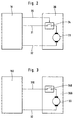
- control device 16 via power supply lines 31 and 32 and via a switch 34 connected to the drive 33 for an actuator.
- the desk 34 is also connected to the control unit via a signal line 35 16 in connection.
- the drive 33 for an actuator and the switch 34 are combined to form a structural unit 35.
- the drive 33 for one of the control elements only via the power supply lines 31 and 32 are turned on, if the switch 34 previously a coded signal has been closed via the signal line 35 is. This coded signal is output by control unit 16.
- Fig. 3 shows a second embodiment with a control device 160, via a supply voltage line 310 and a supply voltage line 32 is connected to a switch 340.
- This switch 340 is in the circuit for the drive 33 for an actuator and is with this drive 33 to a structural unit 360 summarized.
- the switch 360 is over coded signals switched, which via the supply voltage line 310 to the Switch 340 arrive.
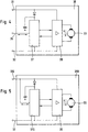
- FIG. 4 shows the circuit arrangement according to FIG. 2 in detail a unit 38 is the drive 33 for an actuator directly with control electronics from a power level 39 and a switching IC 37 connected.
- the switching electronics is via supply voltage lines 31 and 32 connected to the control unit 16.
- the supply voltage lines 31 and 32 also supply the Drive 33 with tension.
- the drive 33 is controlled via a corresponding one Data signal (unidirectional or bidirectional data exchange) via the Signal line 35.
- the switching IC 370 is via a voltage supply line 32 and via a further voltage supply 310 to the control device 16 connected, pass through the voltage supply line 310 encoded signals into the switching IC 370 that cause the drive 33 is switched.
- the signals are on the supply voltage lines for example imprinted by amplitude modulation or pulse modulation.
- the units 36, 360 and 38, 380 are replaced according to the invention the actuators 23 to 28 in an electronic central locking system 1 used according to FIG. 1. This is an operation of these control elements by simply connecting the supply voltage lines at external voltages no longer possible.
Abstract
Description
Die Erfindung bezieht sich auf eine elektronische Zentralverriegelungsanlage für Kraftfahrzeuge bzw. auf eine Betätigungsanlage für Schlösser oder dergl. deren Stellelemente über Versorgungsspannungsleitungen mit einem Steuergerät in Schaltverbindung stehen.The invention relates to an electronic central locking system for motor vehicles or on an actuation system for locks or the like. Their control elements via supply voltage lines are connected to a control unit.
Bei einer bekannten Zentralverriegelungsanlage für Kraftfahrzeuge sind an den Türen, an der Kofferraumklappe und in der Nähe des Anlaßschalters aber auch am Tankverschluß Bedienungsstellen vorgesehen, die als Infrarotempfänger oder auch als Empfänger für andere drahtlose Signale ausgebildet sind.In a known central locking system for motor vehicles are on the doors, on the trunk lid and near the Starter switch but also provided at the tank cap operating points, which as an infrared receiver or as a receiver for other wireless Signals are formed.
Diese Bedienungsstellen sind in der bekannten Zentralverriegelungsanlage alle gleich. Jede Bedienungsstelle besteht aus einer Sendeeinrichtung, die einen Modulator, einen Verstärker und eine IR-Diode enthält, und einer Empfangseinrichtung mit einer Fotodiode, einem Verstärker und einem Demodulator. Jede dieser Bedienungsstellen ist über jeweils zwei Versorgungsspannungsleitungen mit einem Steuergerät verbunden, welches im wesentlichen aus einem Mikrocomputer und einer Schnittstellenschaltung besteht. (DE-OS 36 28 706 A1)These control points are in the known central locking system all the same. Each control point consists of a transmitter, which has a modulator, an amplifier and an IR diode contains, and a receiving device with a photodiode, a Amplifier and a demodulator. Each of these control points is via two supply voltage lines with a control unit connected, which essentially consists of a microcomputer and there is an interface circuit. (DE-OS 36 28 706 A1)
Nachteilig ist, daß diese bekannte Zentralverriegelungsanlage nicht diebstahlssicher ist, weil durch Anlegen von Fremdspannungen an die Versorgungsspannungsleitungen die Stellelemente in die Position "offen" gebracht werden können.The disadvantage is that this known central locking system is not is theft-proof because by applying external voltages to it the supply voltage lines the actuators in position can be brought "open".
Demgegenüber liegt der Erfindung die Aufgabe zugrunde, eine Zentralverriegelungsanlage der geschilderten Art so zu verbessern, daß sie diebstahlssicher ist. In contrast, the invention has for its object a central locking system to improve the type described so that it is theft-proof.
Es wurde gefunden, daß sich diese Aufgabe in einfacher Weise dadurch lösen läßt, daß in den Versorgungsspannungsleitungen zum Antrieb eines Stellelementes ein von einem codierten Signal schaltbarer Schalter angeordnet ist.It has been found that this task is simple can solve that in the supply voltage lines to the drive an actuating element that can be switched by a coded signal Switch is arranged.
Erfindungsgemäß ist gemäß Anspruch 2 der vom codierten Signal schaltbare Schalter in unmittelbarer Nähe des Antriebes für ein Stellelement angeordnet.According to the invention the switchable from the coded signal Switch in the immediate vicinity of the drive for an actuator arranged.
Hierdurch erreicht man, daß das Anlegen von einer Fremdspannung an eine Versorgungsspannungsleitung den Antrieb für ein Stellelement nicht betätigen kann, da die Versorgungsspannungsleitung unmittelbar vor dem Antrieb durch den Schalter unterbrochen ist. Erst wenn durch das richtige Codesignal der Schalter in der Versorgungsspannungsleitung geschlossen wird, kann das Stellelement beeinflußt werden.This ensures that the application of an external voltage the drive for a control element to a supply voltage line can not operate because the supply voltage line immediately before the drive is interrupted by the switch. Only when through the correct code signal of the switches in the supply voltage line is closed, the control element can be influenced.
Die codierten Signale für die Schalten können diesen über Signalleitungen erreichen, die zwischen dem Steuergerät und den Schaltern angeordnet sind.The coded signals for the switching can be done via signal lines reach that between the control unit and the switches are arranged.
Gemäß Anspruch 4 kann die Übermittlung der codierten Signale an
einen Schalter aber auch über die Versorgungsspannungsleitung für
den Antrieb des Stellelementes erfolgen.According to
Von Vorteil ist, wenn gemäß Anspruch 5 der Antrieb für ein Stellelement,
der Schalter bzw. die Schaltelektronik zu einer Baueinheit
zusammengefaßt sind. Eine preiswerte und einfache Schaltung ergibt
sich dann, wenn die Spannungsversorgung für die Baueinheit sowohl
zur Versorgung der Schaltelektronik als auch zur Versorgung des
Antriebes für das Stellelement verwendet wird.It is advantageous if, according to
Bei einem zweiten Ausführungsbeispiel werden zur Ansteuerung der Antriebe für die Stellelemente Datensignale verwendet, die über eigene Datenleitungen an die Schalter bzw. die Schaltelektronik zur Ansteuerung der Antriebe für die Stellelemente gelangen.In a second embodiment, the Drives for the control elements used data signals that over own data lines to the switches or the switching electronics to control the drives for the control elements.
Nach den Ansprüchen 9 und 10 können zum Aufprägen der codierten
Signale auf die Versorgungsspannungen Impulsmodulation oder Amplitudenmodulation
eingesetzt werden.According to
Um die Diebstahlssicherung zu erhöhen, werden die Spannungsversorgungsleitungen und/oder die Signal- bzw. Datenleitungen verdeckt verlegt.To increase the theft protection, the power supply lines and / or the signal or data lines are covered relocated.
Ausführungsbeispiele der Erfindung werden nachfolgend anhand der Zeichnung erläutert.Embodiments of the invention are described below with reference to the Drawing explained.
Es zeigt:
- Fig. 1
- schematisch wesentliche Elemente einer bekannten Zentralverriegelungsanlage,
- Fig. 2
- ein Prinzipschaltbild für ein erstes Ausführungsbeispiel der Erfindung,
- Fig. 3
- ein Prinzipschaltbild für ein zweites Ausführungsbeispiel der Erfindung,
- Fig. 4
- eine detail-iertere Darstellung für das erste Ausführungsbeispiel,
- Fig. 5
- eine detailiertere Darstellung für das zweite Ausführungsbeispiel,
- Fig. 1
- schematically essential elements of a known central locking system,
- Fig. 2
- 2 shows a basic circuit diagram for a first exemplary embodiment of the invention,
- Fig. 3
- 2 shows a basic circuit diagram for a second exemplary embodiment of the invention,
- Fig. 4
- a more detailed representation for the first embodiment,
- Fig. 5
- a more detailed representation for the second embodiment,
In einer bekannte elektronischen Zentralverriegelungsanlage 1 sind
mehrere gleiche Bedienungsstellen 2, 11, 12 und 13 vorgesehen,
von denen der Einfachheit halber nur die Bedienungsstelle 2 näher
erläutert wird. Sie enthält eine Sendeeinrichtung 3 und eine Empfangseinrichtung
4. Die Sendeeinrichtung 3 enthält einen Modulator 5,
einen Verstärker 6 sowie eine IR-Diode 7. Die Empfangsvorrichtung
4 enthält eine Fotodiode 8, einen Verstärker 9 sowie einen Demodulator
10.In a known electronic central locking system 1 are
several identical control points 2, 11, 12 and 13 are provided,
of which, for the sake of simplicity, only the operating point 2 is closer
is explained. It contains a transmitting
Jede der Bedienungsstellen 2, 11, 12 bzw. 13 ist über Leitungen
14 bzw. 15 an ein Steuergerät 16 angeschlossen, welches einen Mikrocomputer
17 und eine Schnittstellenschaltung 18 enthält.Each of the control points 2, 11, 12 and 13 is via
Über Ausgänge 19 und 20 sowie Leistungsstufen 21 und 22 werden
über Versorgungsspannungsleitungen 31 und 32 Stellelemente versorgt.
Beispielsweise dient ein Stellelement 23 für die Fahrertür, ein
Stellelement 24 für die Beifahrertür, ein Stellelement 25 für eine
Fondtür, Stellelement 26 für die andere Fondtür, Stellelement 27
für einen Tankverschluß und Stellelement 28 für einen Kofferraum.Via
Zur Bedienung der Zentralverriegelunqsanlage 1 ist ein Schlüssel
29 vorgesehen, der einen Codesender 30 einschließt. Der Sender und
die Empfänger der Zentralverriegelungsanlage 1 können mit Funk
aber auch mit Infrarotsignalen arbeiten.A key is required to operate the central locking system 1
29 is provided, which includes a
Treffen die vom Codesender 30 abgegebenen Signale auf eine Empfangseinrichtung
4, so gibt diese über die Schnittstellenschaltung 18
ein entsprechendes Signal an den Mikrocomputer 17 ab. Diesem Signal
setzt die Schnittstellenschaltung 18 eine Information darüber zu,
welche Empfangseinrichtung 4 die Signale empfangen hat. Mit Hilfe
des im Mikrocomputer 17 gespeicherten Programms werden aus diesen
Informationen abgeleitet, welche die Stellelemente 23 bis 28 betätigen.
Beim Empfang der drahtlosen Signale an den Bedienungsstellen
2 bzw. 11 werden beispielsweise sämtliche Türen und der Tankdeckel
entriegelt. Beim Empfang der IR-Signale an einer anderen Bedienungsstelle
werden die Türen, der Tankdeckel und die Kofferraumklappe
entriegelt. Beim Empfang drahtloser Signale an der letzten Bedienungsstelle
in der Nähe des Anlaßschalters wird lediglich die Kofferraumklappe
entriegelt.The signals emitted by
Fig. 1 läßt erkennen, daß die Versorgungsspannungsleitungen 31
bzw. 32 direkt an die Stellelemente 23 bis 28 geführt sind. Es
ist erkennbar, daß durch Anlegen von Fremdspannungen an die Versorgungsspannungsleitungen
31, 32 unter Umständen die Stellelemente
in die Position "offen" gestellt werden können.1 shows that the
Die Fig. 2 und 3 zeigen schematisch, wie dieses erfindungsgemäß vermieden werden kann.2 and 3 show schematically how this according to the invention can be avoided.
In einem ersten Ausführungsbeispiel gemäß Fig. 2 ist das Steuergerät
16 über Stromversorgungsleitungen 31 und 32 und über einen Schalter
34 an den Antrieb 33 für ein Stellelement angeschlossen. Der Schalter
34 steht darüberhinaus über eine Signalleitung 35 mit dem Steuergerät
16 in Schaltverbindung. Der Antrieb 33 für ein Stellelement und
der Schalter 34 sind zu eine Baueinheit 35 zusammengefaßt.In a first exemplary embodiment according to FIG. 2, the
Mit Hilfe dieser Schaltungsanordnung kann der Antrieb 33 für eines
der Stellelemente nur dann über die Stromversorgungsleitungen
31 und 32 eingeschaltet werden, wenn zuvor der Schalter 34 durch
ein codiertes Signal über die Signalleitung 35 geschlossen worden
ist. Dieses codierte Signal wird vom Steuergerät 16 ausgegeben.With the help of this circuit arrangement, the
Fig. 3 zeigt ein zweites Ausführungsbeispiel mit einem Steuergerät
160, das über eine Versorgungsspannungsleitung 310 und eine Versorgungsspannungsleitung
32 an einen Schalter 340 angeschlossen ist.
Dieser Schalter 340 liegt im Stromkreis für den Antrieb 33 für
ein Stellelement und ist mit diesem Antrieb 33 zu einer Baueinheit
360 zusammengefaßt. Der Schalter 360 wird über codierte Signale
geschaltet, die über die Versorgungsspannungsleitung 310 an den
Schalter 340 gelangen. Fig. 3 shows a second embodiment with a
Fig. 4 zeigt im Detail die Schaltungsanordnung nach Fig. 2. Auf
einer Baueinheit 38 ist der Antrieb 33 für ein Stellelement unmittelbar
mit einer Steuerelektronik aus einer Leistungsstufe 39 und
einem Schalt-IC 37 verbunden. Die Schaltelektronik wird über Versorgungsspannungsleitungen
31 und 32 mit dem Steuergerät 16 verbunden.
Die Versorgungsspannungsleitungen 31 und 32 versorgen auch den
Antrieb 33 mit Spannung.FIG. 4 shows the circuit arrangement according to FIG. 2 in detail
a
Die Ansteuerung des Antriebes 33 erfolgt über ein entsprechendes
Datensignal (uni- oder bidirektionaler Datenaustausch) über die
Signalleitung 35.The
Gemäß Fig. 5 sind ein Antrieb 33 für ein Stellelement, eine Leistungsstufe
39 und ein Schalt-IC 370 zu einer Baueinheit 380 zusammengefaßt.
Das Schalt-IC 370 ist über eine Spannungsversorgungsleitung 32
und über eine weitere Spannungsversorgung 310 an das Steuergerät
16 angeschlossen, Über die Spannungsversorgungsleitung 310 gelangen
codierte Signale in das Schalt-IC 370, die bewirken, daß der Antrieb
33 geschaltet wird.5 are a
Die Signale sind auf die Versorgungsspannungsleitungen beispielsweise durch Amplitudenmodulation oder Pulsmodulation aufgeprägt.The signals are on the supply voltage lines for example imprinted by amplitude modulation or pulse modulation.
Die Baueinheiten 36, 360 bzw. 38, 380 werden erfindungsgemäß anstelle
der Stellelemente 23 bis 28 in einer elektronischen Zentralverriegelungsanlage
1 gemäß Fig. 1 eingesetzt. Dadurch ist ein Betreiben
dieser Stellelemente durch einfaches Anschließen der Versorgungsspannungsleitungen
an Fremdspannungen nicht mehr möglich. The
- 11
- elektronische Zentralverriegelungsanlageelectronic central locking system
- 22nd
- BedienungsstelleControl panel
- 33rd
- SendeeinrichtungSending device
- 44th
- EmpfangseinrichtungReceiving device
- 55
- Modulatormodulator
- 66
- Verstärkeramplifier
- 77
- IR-DiodeIR diode
- 88th
- FotodiodePhotodiode
- 99
- Verstärkeramplifier
- 1010th
- DemodulatorDemodulator
- 1111
- BedienungsstelleControl panel
- 1212th
- BedienungsstelleControl panel
- 1313
- BedienungsstelleControl panel
- 1414
- Leitungmanagement
- 1515
- Leitungmanagement
- 1616
- SteuergerätControl unit
- 160160
- SteuergerätControl unit
- 1717th
- MikrocomputerMicrocomputer
- 1818th
- SchnittstellenschaltungInterface circuit
- 1919th
- Ausgangexit
- 2020th
- Ausgangexit
- 2121
- LeistungsstufePower level
- 2222
- LeistungsstufePower level
- 2323
- Stellelement, Fahrertür Control element, driver door
- 2424th
- Stellelement, BeifahrertürControl, passenger door
- 2525th
- Stellelement, FondtürControl element, rear door
- 2525th
- Stellelement, FondtürControl element, rear door
- 2727
- Stellelement, TankverschlußControl element, tank cap
- 2828
- Stellelement, KofferraumControl, trunk
- 2929
- Schlüsselkey
- 3030th
- Code-SenderCode transmitter
- 3131
- VersorgungsspannungsleitungSupply voltage line
- 310310
- V ersorgungsspannungsteitung mit SignalübertragungSupply voltage line with signal transmission
- 3232
- VersorgungsspannungsleitungSupply voltage line
- 3333
- Antrieb eines StellelementesDrive of an actuator
- 3434
- Schaltercounter
- 340340
- Schaltercounter
- 3535
- SignalleitungSignal line
- 3636
- BaueinheitUnit
- 360360
- BaueinheitUnit
- 3737
- Schalt-ICSwitching IC
- 370370
- Schalt-ICSwitching IC
- 3838
- BaueinheitUnit
- 380380
- BaueinheitUnit
- 3939
- LeistungsstufePower level
Claims (11)
dadurch gekennzeichnet,
daß die Versorgungsspannungsleitungen (31, 310, 32) zum Antrieb (33) eines Stellelementes (23 - 28)einen von einem codierten Signal schaltbaren Schalter (34, 340, 37, 370) einschließen.Electronic central locking system (1) for motor vehicles or actuation systems for locks or the like, the actuating elements (23 to 28) of which are connected to a control unit (16) via supply voltage lines (31, 32),
characterized,
that the supply voltage lines (31, 310, 32) for driving (33) an actuating element (23-28) include a switch (34, 340, 37, 370) which can be switched by a coded signal.
dadurch gekennzeichnet,
daß der vom codierten Signal schaltbare Schalter (34, 340, 37, 370) in unmittelbarer Nähe des Antriebes (33) für ein Stellelement (23 - 28) angeordnet ist.Central locking system according to claim 1,
characterized,
that the switch (34, 340, 37, 370) which can be switched by the coded signal is arranged in the immediate vicinity of the drive (33) for an actuating element (23-28).
gekennzeichnet durch an das Steuergerät (16, 160) angeschlossene Signalleitungen (35), über die die codierten Signale den Schaltern (34, 37) zugeführt werden.Central locking system according to claims 1 and 2,
characterized by signal lines (35) connected to the control unit (16, 160), via which the coded signals are fed to the switches (34, 37).
daß zur übermittlung der codierten Signale an einen Schalter (340, 370) eine Versorgungsspannungsleitung (310) für den Antrieb (33) eines Stellelementes (23 - 28) verwendet wird.Central locking system according to claims 1 and 2, characterized in that
that a supply voltage line (310) for driving (33) an actuating element (23 - 28) is used to transmit the coded signals to a switch (340, 370).
dadurch gekennzeichnet,
daß der Antrieb (33) eines Stellelementes (23 - 28),der Schalter (34) bzw. die Schaltelektronik (340, 37, 370, 39) zu einer Baueinheit (36, 360, 38, 380) zusammengefaßt sind.Central locking system according to claims 1 and 3,
characterized,
that the drive (33) of an actuating element (23-28), the switch (34) or the switching electronics (340, 37, 370, 39) are combined to form a structural unit (36, 360, 38, 380).
dadurch gekennzeichnet,
daß die Spannungsversorgung für die Baueinheit (36, 360, 38, 380) sowohl zur Versorgung der Schaltelektronic (340, 37, 370, 39) als auch zur Versorgung des Antriebes (33) für das Stellelement (23 - 28) verwendet wird.Central locking system according to claim 5,
characterized,
that the voltage supply for the structural unit (36, 360, 38, 380) is used both to supply the switching electronics (340, 37, 370, 39) and to supply the drive (33) for the control element (23 - 28).
dadurch gekennzeichnet,
daß zur Ansteuerung des Antriebes (33) für ein Stellelement (23 - 28) Datensignale verwendet werden, die über Datenleitungen (35) an die Schalter (34) bzw. die Schaltelektronik (340, 37, 370, 39) angeschlossen sind.Central locking system according to one or more of the preceding claims,
characterized,
that to control the drive (33) for an actuator (23 - 28) data signals are used, which are connected via data lines (35) to the switches (34) or the switching electronics (340, 37, 370, 39).
dadurch gekennzeichnet,
daß zur Ansteuerung des Antriebes (33) für ein Schaltelement (23 - 28) codierte Signale verwendet werden, die den Schaltern (34) bzw. der Schaltelektronik (340, 37, 370, 39) über Versorgungsspannungsleitungen (31, 310, 32) zugeführt werden.Central locking system according to claims 1 to 4,
characterized,
that coded signals are used to control the drive (33) for a switching element (23 - 28), which are fed to the switches (34) or the switching electronics (340, 37, 370, 39) via supply voltage lines (31, 310, 32) will.
dadurch gekennzeichnet,
daß zum Aufprägen der codierten Signale auf die Versorgungsspannungen Amplitudenmodulation verwendet wird.Central locking system according to claim 8,
characterized,
that amplitude modulation is used to impress the coded signals on the supply voltages.
dadurch gekennzeichnet,
daß zum Aufprägen der codierten Signale auf die Versorgungsspannungen Pulsmodulation verwendet wird.Central locking system according to claim 8,
characterized,
that pulse modulation is used to impress the coded signals on the supply voltages.
dadurch gekennzeichnet,
daß die Versorgungsspannungsleitungen (31, 310, 32) und die Signal- bzw. Datenleitungen (35) verdeckt verlegt sind.Central locking system according to one or more of the preceding claims,
characterized,
that the supply voltage lines (31, 310, 32) and the signal or data lines (35) are concealed.
Applications Claiming Priority (2)
| Application Number | Priority Date | Filing Date | Title |
|---|---|---|---|
| DE19822887 | 1998-05-22 | ||
| DE19822887A DE19822887A1 (en) | 1998-05-22 | 1998-05-22 | Electronic central locking system |
Publications (2)
| Publication Number | Publication Date |
|---|---|
| EP0959207A2 true EP0959207A2 (en) | 1999-11-24 |
| EP0959207A3 EP0959207A3 (en) | 2001-11-21 |
Family
ID=7868575
Family Applications (1)
| Application Number | Title | Priority Date | Filing Date |
|---|---|---|---|
| EP99109013A Withdrawn EP0959207A3 (en) | 1998-05-22 | 1999-05-06 | Electronic central locking system |
Country Status (4)
| Country | Link |
|---|---|
| US (1) | US6369458B2 (en) |
| EP (1) | EP0959207A3 (en) |
| JP (1) | JPH11350811A (en) |
| DE (1) | DE19822887A1 (en) |
Families Citing this family (5)
| Publication number | Priority date | Publication date | Assignee | Title |
|---|---|---|---|---|
| US6862456B2 (en) * | 2002-03-01 | 2005-03-01 | Cognio, Inc. | Systems and methods for improving range for multicast wireless communication |
| DE10226252B4 (en) * | 2002-06-13 | 2009-04-02 | Robert Bosch Gmbh | Circuit arrangement for supplying power to at least one electrically actuatable opening mechanism of a motor vehicle |
| US20050200482A1 (en) * | 2004-03-10 | 2005-09-15 | Kurple William M. | Storage box alarm |
| DE102004038119A1 (en) * | 2004-08-05 | 2006-02-23 | Siemens Ag | Electric locking system |
| JP2016098571A (en) * | 2014-11-21 | 2016-05-30 | 株式会社東海理化電機製作所 | Door lock control system |
Citations (1)
| Publication number | Priority date | Publication date | Assignee | Title |
|---|---|---|---|---|
| DE3628706A1 (en) | 1986-08-23 | 1988-02-25 | Vdo Schindling | CENTRAL LOCKING SYSTEM FOR A MOTOR VEHICLE |
Family Cites Families (14)
| Publication number | Priority date | Publication date | Assignee | Title |
|---|---|---|---|---|
| DE3225754A1 (en) * | 1982-07-09 | 1984-01-12 | Hülsbeck & Fürst GmbH & Co KG, 5620 Velbert | METHOD FOR THE LOCKING EFFECTIVE INTERACTION OF A KEY-LIKE PART WITH A LOCK-LIKE PART |
| US4736367A (en) * | 1986-12-22 | 1988-04-05 | Chrysler Motors Corporation | Smart control and sensor devices single wire bus multiplex system |
| GB2266392B (en) * | 1992-04-16 | 1995-10-11 | Equus Inc | A three-line type of vehicle burglar-detecting system |
| US5349459A (en) * | 1992-05-18 | 1994-09-20 | Rockwell International Corporation | Secure remote control system |
| US5574343A (en) * | 1992-12-02 | 1996-11-12 | Vdo Adolf Schindling Ag | Control of activators in motor vehicle doors |
| DE4427254B4 (en) * | 1994-07-30 | 2004-02-26 | Kiekert Ag | Locking system for a motor vehicle |
| DE4427253C2 (en) * | 1994-07-30 | 1996-05-23 | Kiekert Ag | Locking system for a motor vehicle |
| DE19530720B4 (en) * | 1995-08-18 | 2004-07-22 | Kiekert Ag | central locking system |
| DE19530724A1 (en) * | 1995-08-18 | 1997-02-20 | Kiekert Ag | Control system for vehicle door central locking |
| US5751072A (en) * | 1996-01-02 | 1998-05-12 | Hwang; Shih Ming | Vehicle security system using an existing switch device, ignition key manipulation, and remote control transmitter to disarm the system and program security codes |
| DE19633202C1 (en) * | 1996-08-17 | 1997-09-11 | Kiekert Ag | Control system for motor vehicle door locking with emergency operating mode |
| DE19639896A1 (en) * | 1996-09-27 | 1998-04-16 | Bosch Gmbh Robert | Locking device |
| DE19643013C1 (en) * | 1996-10-18 | 1998-02-12 | Telefunken Microelectron | Data transmission system for automobile decentralised control system |
| US5874785A (en) * | 1997-12-04 | 1999-02-23 | Continocean Tech Inc. | Keyless motor vehicle starting system |
-
1998
- 1998-05-22 DE DE19822887A patent/DE19822887A1/en not_active Ceased
-
1999
- 1999-05-06 EP EP99109013A patent/EP0959207A3/en not_active Withdrawn
- 1999-05-20 US US09/315,392 patent/US6369458B2/en not_active Expired - Fee Related
- 1999-05-21 JP JP14189899A patent/JPH11350811A/en active Pending
Patent Citations (1)
| Publication number | Priority date | Publication date | Assignee | Title |
|---|---|---|---|---|
| DE3628706A1 (en) | 1986-08-23 | 1988-02-25 | Vdo Schindling | CENTRAL LOCKING SYSTEM FOR A MOTOR VEHICLE |
Also Published As
| Publication number | Publication date |
|---|---|
| DE19822887A1 (en) | 1999-12-02 |
| JPH11350811A (en) | 1999-12-21 |
| US6369458B2 (en) | 2002-04-09 |
| US20020000755A1 (en) | 2002-01-03 |
| EP0959207A3 (en) | 2001-11-21 |
Similar Documents
| Publication | Publication Date | Title |
|---|---|---|
| DE19706393B4 (en) | Motor vehicle with electronic control device for operating the motor vehicle door with a motor vehicle door lock | |
| DE4427254B4 (en) | Locking system for a motor vehicle | |
| EP0365866B1 (en) | Central locking device for a plurality of units and/or parts of an entire installation, in particular an anti-theft device for motor vehicles | |
| DE3737468A1 (en) | DOOR LOCKING SYSTEM FOR A MOTOR VEHICLE | |
| DE3341900C2 (en) | ||
| DE10243318A1 (en) | Drive authorization system | |
| DE3918052C1 (en) | ||
| DE3921893C2 (en) | Electronic identification system, in particular for actuating steering lock theft locks, door locks and other automotive applications | |
| EP1544388A1 (en) | Motor vehicle | |
| DE3306863A1 (en) | Lock system for motor vehicles, in particular steering lock system | |
| EP0257212A2 (en) | Central locking system for a motor vehicle | |
| EP0959207A2 (en) | Electronic central locking system | |
| DE102006035803A1 (en) | Vehicle e.g. car, has unit that is attached to device to induce switch-over of power supply to emergency battery on emergency control unit in particular on direct signal line during emergency situation | |
| DE19801543B4 (en) | Portable remote control unit, in particular for an anti-theft system for a motor vehicle, and method for operating the remote control unit | |
| DE10333297B4 (en) | Method and device for controlling antennas of a remote control system of a motor vehicle | |
| DE102008062627A1 (en) | System and method for remote activation using a transmitter-switch arrangement | |
| DE4309527C2 (en) | Remote control transmitter | |
| DE19907374B4 (en) | Electronic ignition lock system for a motor vehicle | |
| DE10031468A1 (en) | Vehicle distance wireless closure unit control having RF/IR transmitters with logic selection circuits and pulse generators time interval operating transmitters | |
| DE19639896A1 (en) | Locking device | |
| DE3442356A1 (en) | Central-locking system for a motor vehicle | |
| DE102005021377A1 (en) | Motor vehicle locking system and method for obtaining access to a motor vehicle by means of such a system | |
| EP0923054A2 (en) | Method and device for checking the usage right for access control devices | |
| DE4240403C1 (en) | Control system setting adjusting elements in motor vehicle door - uses passive components, e.g. resistance and capacitor, for producing control commands along with at least one electric motor and operating element housed in door | |
| DE102004039835B3 (en) | Electronic access system for motor vehicle combines retrofitted passive electronic access system with remote access system already in vehicle |
Legal Events
| Date | Code | Title | Description |
|---|---|---|---|
| PUAI | Public reference made under article 153(3) epc to a published international application that has entered the european phase |
Free format text: ORIGINAL CODE: 0009012 |
|
| AK | Designated contracting states |
Kind code of ref document: A2 Designated state(s): AT BE CH CY DE DK ES FI FR GB GR IE IT LI LU MC NL PT SE Kind code of ref document: A2 Designated state(s): DE FR GB |
|
| AX | Request for extension of the european patent |
Free format text: AL;LT;LV;MK;RO;SI |
|
| PUAL | Search report despatched |
Free format text: ORIGINAL CODE: 0009013 |
|
| AK | Designated contracting states |
Kind code of ref document: A3 Designated state(s): AT BE CH CY DE DK ES FI FR GB GR IE IT LI LU MC NL PT SE |
|
| AX | Request for extension of the european patent |
Free format text: AL;LT;LV;MK;RO;SI |
|
| RAP1 | Party data changed (applicant data changed or rights of an application transferred) |
Owner name: SIEMENS AKTIENGESELLSCHAFT |
|
| AKX | Designation fees paid |
Free format text: DE FR GB |
|
| STAA | Information on the status of an ep patent application or granted ep patent |
Free format text: STATUS: THE APPLICATION IS DEEMED TO BE WITHDRAWN |
|
| 18D | Application deemed to be withdrawn |
Effective date: 20020522 |