EP0958631B1 - Frame and loading apparatus for groups of battery plates - Google Patents
Frame and loading apparatus for groups of battery plates Download PDFInfo
- Publication number
- EP0958631B1 EP0958631B1 EP97918266A EP97918266A EP0958631B1 EP 0958631 B1 EP0958631 B1 EP 0958631B1 EP 97918266 A EP97918266 A EP 97918266A EP 97918266 A EP97918266 A EP 97918266A EP 0958631 B1 EP0958631 B1 EP 0958631B1
- Authority
- EP
- European Patent Office
- Prior art keywords
- groups
- walls
- frame
- group
- box
- Prior art date
- Legal status (The legal status is an assumption and is not a legal conclusion. Google has not performed a legal analysis and makes no representation as to the accuracy of the status listed.)
- Expired - Lifetime
Links
- 230000006835 compression Effects 0.000 claims abstract description 12
- 238000007906 compression Methods 0.000 claims abstract description 12
- 210000004027 cell Anatomy 0.000 claims description 19
- 230000000717 retained effect Effects 0.000 claims description 5
- 210000002421 cell wall Anatomy 0.000 claims description 2
- 230000006798 recombination Effects 0.000 description 6
- 238000005215 recombination Methods 0.000 description 6
- 238000003780 insertion Methods 0.000 description 3
- 230000037431 insertion Effects 0.000 description 3
- 238000000034 method Methods 0.000 description 3
- 238000005266 casting Methods 0.000 description 2
- 239000003792 electrolyte Substances 0.000 description 2
- 101000964746 Homo sapiens Zinc finger protein 69 Proteins 0.000 description 1
- UFHFLCQGNIYNRP-UHFFFAOYSA-N Hydrogen Chemical compound [H][H] UFHFLCQGNIYNRP-UHFFFAOYSA-N 0.000 description 1
- 101100221607 Saccharomyces cerevisiae (strain ATCC 204508 / S288c) COS8 gene Proteins 0.000 description 1
- 102100040717 Zinc finger protein 69 Human genes 0.000 description 1
- 239000002253 acid Substances 0.000 description 1
- QVGXLLKOCUKJST-UHFFFAOYSA-N atomic oxygen Chemical compound [O] QVGXLLKOCUKJST-UHFFFAOYSA-N 0.000 description 1
- 230000015572 biosynthetic process Effects 0.000 description 1
- 238000010276 construction Methods 0.000 description 1
- 230000001419 dependent effect Effects 0.000 description 1
- 238000005755 formation reaction Methods 0.000 description 1
- 239000003365 glass fiber Substances 0.000 description 1
- 239000001257 hydrogen Substances 0.000 description 1
- 229910052739 hydrogen Inorganic materials 0.000 description 1
- 238000011065 in-situ storage Methods 0.000 description 1
- 238000004519 manufacturing process Methods 0.000 description 1
- 239000000463 material Substances 0.000 description 1
- 239000002184 metal Substances 0.000 description 1
- 239000001301 oxygen Substances 0.000 description 1
- 229910052760 oxygen Inorganic materials 0.000 description 1
- 125000006850 spacer group Chemical group 0.000 description 1
- XLYOFNOQVPJJNP-UHFFFAOYSA-N water Substances O XLYOFNOQVPJJNP-UHFFFAOYSA-N 0.000 description 1
Images


Classifications
-
- H—ELECTRICITY
- H01—ELECTRIC ELEMENTS
- H01M—PROCESSES OR MEANS, e.g. BATTERIES, FOR THE DIRECT CONVERSION OF CHEMICAL ENERGY INTO ELECTRICAL ENERGY
- H01M10/00—Secondary cells; Manufacture thereof
- H01M10/04—Construction or manufacture in general
- H01M10/0404—Machines for assembling batteries
-
- H—ELECTRICITY
- H01—ELECTRIC ELEMENTS
- H01M—PROCESSES OR MEANS, e.g. BATTERIES, FOR THE DIRECT CONVERSION OF CHEMICAL ENERGY INTO ELECTRICAL ENERGY
- H01M10/00—Secondary cells; Manufacture thereof
- H01M10/06—Lead-acid accumulators
- H01M10/12—Construction or manufacture
-
- H—ELECTRICITY
- H01—ELECTRIC ELEMENTS
- H01M—PROCESSES OR MEANS, e.g. BATTERIES, FOR THE DIRECT CONVERSION OF CHEMICAL ENERGY INTO ELECTRICAL ENERGY
- H01M10/00—Secondary cells; Manufacture thereof
- H01M10/06—Lead-acid accumulators
- H01M10/12—Construction or manufacture
- H01M10/14—Assembling a group of electrodes or separators
-
- Y—GENERAL TAGGING OF NEW TECHNOLOGICAL DEVELOPMENTS; GENERAL TAGGING OF CROSS-SECTIONAL TECHNOLOGIES SPANNING OVER SEVERAL SECTIONS OF THE IPC; TECHNICAL SUBJECTS COVERED BY FORMER USPC CROSS-REFERENCE ART COLLECTIONS [XRACs] AND DIGESTS
- Y02—TECHNOLOGIES OR APPLICATIONS FOR MITIGATION OR ADAPTATION AGAINST CLIMATE CHANGE
- Y02E—REDUCTION OF GREENHOUSE GAS [GHG] EMISSIONS, RELATED TO ENERGY GENERATION, TRANSMISSION OR DISTRIBUTION
- Y02E60/00—Enabling technologies; Technologies with a potential or indirect contribution to GHG emissions mitigation
- Y02E60/10—Energy storage using batteries
-
- Y—GENERAL TAGGING OF NEW TECHNOLOGICAL DEVELOPMENTS; GENERAL TAGGING OF CROSS-SECTIONAL TECHNOLOGIES SPANNING OVER SEVERAL SECTIONS OF THE IPC; TECHNICAL SUBJECTS COVERED BY FORMER USPC CROSS-REFERENCE ART COLLECTIONS [XRACs] AND DIGESTS
- Y02—TECHNOLOGIES OR APPLICATIONS FOR MITIGATION OR ADAPTATION AGAINST CLIMATE CHANGE
- Y02P—CLIMATE CHANGE MITIGATION TECHNOLOGIES IN THE PRODUCTION OR PROCESSING OF GOODS
- Y02P70/00—Climate change mitigation technologies in the production process for final industrial or consumer products
- Y02P70/50—Manufacturing or production processes characterised by the final manufactured product
-
- Y—GENERAL TAGGING OF NEW TECHNOLOGICAL DEVELOPMENTS; GENERAL TAGGING OF CROSS-SECTIONAL TECHNOLOGIES SPANNING OVER SEVERAL SECTIONS OF THE IPC; TECHNICAL SUBJECTS COVERED BY FORMER USPC CROSS-REFERENCE ART COLLECTIONS [XRACs] AND DIGESTS
- Y10—TECHNICAL SUBJECTS COVERED BY FORMER USPC
- Y10T—TECHNICAL SUBJECTS COVERED BY FORMER US CLASSIFICATION
- Y10T29/00—Metal working
- Y10T29/49—Method of mechanical manufacture
- Y10T29/49002—Electrical device making
- Y10T29/49108—Electric battery cell making
-
- Y—GENERAL TAGGING OF NEW TECHNOLOGICAL DEVELOPMENTS; GENERAL TAGGING OF CROSS-SECTIONAL TECHNOLOGIES SPANNING OVER SEVERAL SECTIONS OF THE IPC; TECHNICAL SUBJECTS COVERED BY FORMER USPC CROSS-REFERENCE ART COLLECTIONS [XRACs] AND DIGESTS
- Y10—TECHNICAL SUBJECTS COVERED BY FORMER USPC
- Y10T—TECHNICAL SUBJECTS COVERED BY FORMER US CLASSIFICATION
- Y10T29/00—Metal working
- Y10T29/53—Means to assemble or disassemble
- Y10T29/5313—Means to assemble electrical device
- Y10T29/53135—Storage cell or battery
Definitions
- This invention relates to apparatus for loading battery plate groups into a battery box and, in particular, but not exclusively to loading groups for recombination batteries.
- Recombination batteries i.e. batteries in which the hydrogen and oxygen recombine to form water
- separators of microporous glass fibre in which the acid electrolyte is fully absorbed.
- the separator material is extremely delicate and the group has to be loaded into the battery box in a compressed state (and retained in chat state by the box) in order to ensure that the electrolyte is in active contact wich the plates.
- the invention consists in a frame for use in loading groups of battery plates into respective cells in a box, comprising a plurality of spaced walls defining respective group receiving spaces, the walls being moveable away from and towards each other to allow groups to be inserted in the spaces and subsequently grippingly retained therein and compressed by the walls, and guide means mounted at the lower end of the walls to locate in the cells and form a continuous surface with the walls characterised in that guide means extend across the full width of the walls, cells or groups, and in that the groups may be loaded from the frame whilst still under compression.
- the frame further comprises stop means for each space insertable between a respective pair of walls into the respective space to locate the bottom edge of a group when it is placed into the space.
- the invention consists in a frame for use in loading groups of battery plates into respective cells in a box, comprising a plurality of spaced walls defining respective group receiving spaces, the walls being moveable away from and towards each other to allow groups to be inserted into the spaces and subsequently grippingly retained therein by the walls characterised in that it further comprises removable stop means for each space insertable between a respective pair of walls into the respective space to locate the bottom edge of a group when it is placed into the space.
- the stop means locates the group against downward movement and lateral movement relative to the mid-plane of the group.
- the stop means should be removable from the spaces.
- the stop means may provide orthogonal abutments and may be rotatable about an axis adjacent to the intersection of the abutments so that the stop means can be rotated into and out of the space.
- the stop means may also be moveable with or in relation to the walls to maintain their relative location vis-à-vis the walls.
- the distance between the group bottom edge location defined by the stop means and the top of its associated walls in preferably greater than the total height of the groups. This prevents any part of the group becoming snagged on the edges of the walls during insertion from the frame.
- the invention consists in battery group loading apparatus including a frame as defined above and further comprising means for loading groups into respective spaces in the frame to sit on the respective stop means, means for moving the walls towards each other to grip the groups between the walls, means for removing the stop means from the spaces, means for engaging a battery box with the guide means and means for pushing the groups through the guide means into the box.
- the means for moving the walls towards each other are designed to exert compressive forces on the groups, in which case this force can be maintained during the operation of the pushing means.
- the pushing means may act simultaneously on all the groups and may have heads, each of which may be formed with formations to cooperate with the terminal posts or straps cast on the groups so as to achieve precise location between the head and the group.
- the invention includes apparatus for unloading a battery group from a jig box including support means for engaging the bottom of a group on a support, whilst the group is held in a jig box, means for releasing the groups within the jig box, means for raising the support to a level at which a substantial portion of a supported group would stand clear of the jig box and means for gripping the raised group.
- the support may include lateral abutments for preventing sideways movements of the group during raising.
- the invention consists in apparatus for unloading groups with cast on straps from a jig box and for loading those groups into a battery box comprising the apparatus for unloading as defined above and the battery group loading apparatus as defined above.
- the invention consists in a method of unloading a battery group from a jig box including engaging the bottom of a group on a support, releasing the grip of the jig box on the group, raising the support and hence the group until a substantial portion of the group is clear of the jig box and gripping the raised group.
- both the jig box and the gripping means may be provided with gripping surfaces which are continuous over the whole portion which engages the group. This prevents damage and marking of the outside separators.
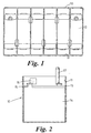
- Figure 1 illustrates a battery box 10 have cells 11 in which groups 12 have been inserted.
- the groups 12 comprise interleaved separators 13 and plates 14.
- the plates 14 have lugs 15 onto which straps 16 or terminal posts 17 have been cast by a machine for casting on such straps.
- Each jig box comprises a number of spaces or cells into which groups can be loaded at a loading station and the jig boxes have walls which can be moved towards and away from each other to group and release the groups.
- the table indexed around the groups pass through stations in which they are aligned, the lugs cleaned and fluxed, and have straps and terminal posts cast on them so that by the time a jig box arrives at an unloading station it contains, in the correct order and alignment, a set of groups 12 ready for loading into a battery box.
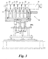
- Such an unloading station is illustrated in Figure 3 and is generally indicated 18.
- the unloading station 18 has a number of new and inventive features.
- a jig box 19 is illustrated at the station and it can be seen that it defines a plurality of side-by-side spaces 20 in which the groups are contained. (The groups are not shown in Figure 3).
- the jig box 19 arrives at the unloading station 18 the groups 12 are gripped within the spaces 20.
- the walls 21 of the jig box 19 are continuous and extend over almost the full area of the engaged faces on the groups 12. This means that it is not possible to remove the groups from the jig box by the traditional method of passing gripping fingers through gaps in the wall to engage the groups.
- the Applicant has overcome this problem by providing a series of supports 22 which are initially raised to the position shown in Figure 3 at which they engage the lower most edge of the groups 12, as indicated by the broken line 23. (The supports 22 may have upstanding ends (not shown) to restrict lateral movement of the groups 12.)
- the walls 21 can be moved marginally away from each other to release the groups, whereupon further upward movement of the supports 22 allows the groups 12 to be pushed up through the spaces 20 so that they stand substantially proud of the jig box 19 as illustrated at 24 in Figure 4.
- the groups 12 are engaged by plates 25 of gripper heads 26 and they can then be raised out of the jig boxes as illustrated at 27 in Figure 4.
- the removed groups 12 can then be transported laterally by the heads 26 until they overlie a compression frame, which is generally indicated at 28, as can be seen in Figure 5.
- the compression frame 28 is more fully illustrated in Figures 6 and 7 and includes two end pieces 29, 30, which are interconnected, at each side, by pairs of vertically spaced horizontal rods 31-34. Walls 35 are slidably mounted on the upper rods 31-32, whilst stops 36 are rotatably and slidably mounted on the lower rods 33-34; there being a pair of opposed stops 36 for each group space 37 defined between a pair a of adjacent walls 35.
- the walls 35 and stops 36 are interlinked by respective chains 38,39 so that when an end stop and wall combination 40 is pulled away from its adjacent wall, the other walls and stops are pulled apart equally to spacing defined by the lengths of the chains.
- This movement is obtained by cylinder 60, which can also move in the opposite direction to compress the walls 35 together to spacings defined by spacers 41.
- each stop 36 comprises a generally rectangular body 42, which is slidably and rotatably mounted on a respective rod 33,34, and a projecting foot 43 for supporting the bottom of a group 12.
- the inward ends 44 of the bodies 42 define lateral abutments for the groups 12 so that they cannot move in a sideways direction.
- the bodies 42 on each side are interlinked as a set by respective rods 45, which can be used to rotate the stops 36 from their support position, which is shown in Figure 5 to a generally vertical position in which they completely disengage the groups 12.
- Each wall 35 carries one or more guide shims, which are designed to project into associated cells 11 of the battery box so that they define a guide surface for the groups to be slid along as they move into the respective cells 11.
- the shims 46 are formed continuously with their associated walls 35 so that there are no edges or projections which can damage the groups.
- the walls 35 and their shims 46 are formed from a single piece of highly polished flexible metal. The height of the walls from the location defined by the feet 43 is greater than the height of the groups, so that, once inserted, the groups cannot catch on any part of the wall and the width of the walls is greater than the width of the groups.
- a rectangular guide frame 47 which receives and locates the frame 28 relative to a battery box 10 carried on a conveyor 49.
- the guide frame 47 has a tapered open mouth 49 so that the box 10 is not damaged, when the frame 47 is engaged on it and equally the groups do not snag on the box 10 during insertion.
- the groups 12 held in the gripping heads 26 are loaded into respective spaces between pair of walls 35, when the walls are in their "open" position.
- the stops are arranged as shown in Figure 5 and so the groups are supported within their respective spaces by pairs of feet 43 and are laterally located by ends 44.
- the walls 35 are then drawn together by cylinder 60 until they both grip and compress the groups 12.
- Adjustable stops 40a define the limit of compression and may be provided in addition to or instead of stops 41. Their advantage is that they allow easy adjustment for different battery size.
- Stops 41 are in any case used for 'dry' running the machine.)
- the frame 28 is then lowered downwardly onto a battery box 10 which has been brought to the correct position by a conveyor 50 and the exact relative position between the battery box 10 and the frame 28 is defined by the guide frame 47.
- the stops 36 can be swung out so that the groups can then be pushed downwardly, whilst still under compression into the cells 11. Because the walls 35 and shims 46 provide a continuous surface this is achieved simply, swiftly and without damage.
- the pusher comprises a number of laterally spaced vertically dependent rods 52 each of which carries a head 53 at its free end.
- the upper ends of the rods 52 are located on a plate 54, which can be raised and lowered by a cylinder 55.
- the heads 53 are profiled so that they precisely receive the upper surface of the group, the exact shape being determined by whether the engaged group includes end terminals or simply straps. This profiling not only protects the group, but ensures very precise alignment between the heads 53 and the groups 12.
- stops could be slid in and out of the spaces, in which case a pair of stops could be constituted by a single element. Equally a single stop element might be swung up from one side.
Landscapes
- Engineering & Computer Science (AREA)
- Manufacturing & Machinery (AREA)
- Chemical & Material Sciences (AREA)
- Chemical Kinetics & Catalysis (AREA)
- Electrochemistry (AREA)
- General Chemical & Material Sciences (AREA)
- Secondary Cells (AREA)
- Sealing Battery Cases Or Jackets (AREA)
- Battery Mounting, Suspending (AREA)
- Discharge By Other Means (AREA)
- Connection Of Batteries Or Terminals (AREA)
- Charge And Discharge Circuits For Batteries Or The Like (AREA)
- Vending Machines For Individual Products (AREA)
- Supplying Of Containers To The Packaging Station (AREA)
Abstract
Description
- This invention relates to apparatus for loading battery plate groups into a battery box and, in particular, but not exclusively to loading groups for recombination batteries.
- Recombination batteries (i.e. batteries in which the hydrogen and oxygen recombine to form water) tend to have separators of microporous glass fibre in which the acid electrolyte is fully absorbed. The separator material is extremely delicate and the group has to be loaded into the battery box in a compressed state (and retained in chat state by the box) in order to ensure that the electrolyte is in active contact wich the plates.
- It will readily be appreciated that there are significant difficulties in inserting the compressed group into the battery box cell when that cell is substantially the same size without damaging the separators.
- There are also problems in transferring such groups from the processing jig boxes, because the walls in the jig boxes which apply the compression can mark the separators if they do not act over the full separator surface. Accordingly attempts have been made to load the groups directly from the jig box by providing guides on the ends of the jig box walls. However, these guides can only extend partially across the width of the battery cell, because space must be allowed for the transverse supports on which the group elements sit when the jig box is being loaded. The result is that the unguided portions of the groups snag on the box wall.
- From one aspect the invention consists in a frame for use in loading groups of battery plates into respective cells in a box, comprising a plurality of spaced walls defining respective group receiving spaces, the walls being moveable away from and towards each other to allow groups to be inserted in the spaces and subsequently grippingly retained therein and compressed by the walls, and guide means mounted at the lower end of the walls to locate in the cells and form a continuous surface with the walls characterised in that guide means extend across the full width of the walls, cells or groups, and in that the groups may be loaded from the frame whilst still under compression.
- It is particulary preferred that the frame further comprises stop means for each space insertable between a respective pair of walls into the respective space to locate the bottom edge of a group when it is placed into the space.
- From another aspect the invention consists in a frame for use in loading groups of battery plates into respective cells in a box, comprising a plurality of spaced walls defining respective group receiving spaces, the walls being moveable away from and towards each other to allow groups to be inserted into the spaces and subsequently grippingly retained therein by the walls characterised in that it further comprises removable stop means for each space insertable between a respective pair of walls into the respective space to locate the bottom edge of a group when it is placed into the space.
- Conveniently, in either case, the stop means locates the group against downward movement and lateral movement relative to the mid-plane of the group. In any of these cases, the stop means should be removable from the spaces. Thus, for example, the stop means may provide orthogonal abutments and may be rotatable about an axis adjacent to the intersection of the abutments so that the stop means can be rotated into and out of the space. The stop means may also be moveable with or in relation to the walls to maintain their relative location vis-à-vis the walls.
- The distance between the group bottom edge location defined by the stop means and the top of its associated walls in preferably greater than the total height of the groups. This prevents any part of the group becoming snagged on the edges of the walls during insertion from the frame.
- From yet another aspect the invention consists in battery group loading apparatus including a frame as defined above and further comprising means for loading groups into respective spaces in the frame to sit on the respective stop means, means for moving the walls towards each other to grip the groups between the walls, means for removing the stop means from the spaces, means for engaging a battery box with the guide means and means for pushing the groups through the guide means into the box.
- Preferably the means for moving the walls towards each other are designed to exert compressive forces on the groups, in which case this force can be maintained during the operation of the pushing means.
- The pushing means may act simultaneously on all the groups and may have heads, each of which may be formed with formations to cooperate with the terminal posts or straps cast on the groups so as to achieve precise location between the head and the group.
- From another aspect the invention includes apparatus for unloading a battery group from a jig box including support means for engaging the bottom of a group on a support, whilst the group is held in a jig box, means for releasing the groups within the jig box, means for raising the support to a level at which a substantial portion of a supported group would stand clear of the jig box and means for gripping the raised group. The support may include lateral abutments for preventing sideways movements of the group during raising.
- From a further aspect the invention consists in apparatus for unloading groups with cast on straps from a jig box and for loading those groups into a battery box comprising the apparatus for unloading as defined above and the battery group loading apparatus as defined above.
- From a still further aspect the invention consists in a method of unloading a battery group from a jig box including engaging the bottom of a group on a support, releasing the grip of the jig box on the group, raising the support and hence the group until a substantial portion of the group is clear of the jig box and gripping the raised group.
- The advantage of this method and the associated apparatus defined above, is that, in contrast to existing gripping arrangements (where the groups are gripped through openings in the jig box, whilst the groups are still in the box) is that both the jig box and the gripping means may be provided with gripping surfaces which are continuous over the whole portion which engages the group. This prevents damage and marking of the outside separators.
- The invention may be performed in various ways and a specific embodiment will now be described, by way of example, with the reference to the accompanying drawings, in which:
- Figure 1 is a view from above of a recombination battery with its lid removed;
- Figure 2 is a vertical section through an end cell of Figure 1 showing the group in situ;
- Figure 3 is a part schematic view of an unloading station of a machine for casting straps on battery groups;
- Figure 4 is a diagrammatic representation of the removal of groups from the jig box of the machine of Figure 3;
- Figure 5 is a diagrammatic representation of a loading configuration and illustrates in descending order a gripper holding groups, a compression frame and a battery box on a conveyor;
- Figure 6 is a view from above on the compression frame of Figure 5;
- Figure 7 is a schematic partial side view of part of the frame of Figure 6; and
- Figure 8 is a edge view of a stuffing tool for pushing the groups from the frame of Figure 7 into a battery box.
-
- As has been mentioned previously recombination batteries require that the battery groups of plates and separators are inserted into the cells of a battery box under compression and that that compression is maintained by the walls of the battery box cells.
- Figure 1 illustrates a
battery box 10 havecells 11 in whichgroups 12 have been inserted. Thegroups 12 compriseinterleaved separators 13 andplates 14. Theplates 14 havelugs 15 onto whichstraps 16 orterminal posts 17 have been cast by a machine for casting on such straps. - Whilst such machines can take a number of forms, they now typically comprise a rotatable table which can support jig boxes in a series of circumferentially spaced locations. Each jig box comprises a number of spaces or cells into which groups can be loaded at a loading station and the jig boxes have walls which can be moved towards and away from each other to group and release the groups. As the table indexed around the groups pass through stations in which they are aligned, the lugs cleaned and fluxed, and have straps and terminal posts cast on them so that by the time a jig box arrives at an unloading station it contains, in the correct order and alignment, a set of
groups 12 ready for loading into a battery box. The Applicants sell examples of such machines under the Trade Marks COS5 and COS8. - Such an unloading station is illustrated in Figure 3 and is generally indicated 18. However the
unloading station 18 has a number of new and inventive features. Ajig box 19 is illustrated at the station and it can be seen that it defines a plurality of side-by-side spaces 20 in which the groups are contained. (The groups are not shown in Figure 3). When thejig box 19 arrives at theunloading station 18 thegroups 12 are gripped within thespaces 20. Contrary to traditional jig boxes designed for automatic unloading, thewalls 21 of thejig box 19 are continuous and extend over almost the full area of the engaged faces on thegroups 12. This means that it is not possible to remove the groups from the jig box by the traditional method of passing gripping fingers through gaps in the wall to engage the groups. The Applicant has overcome this problem by providing a series ofsupports 22 which are initially raised to the position shown in Figure 3 at which they engage the lower most edge of thegroups 12, as indicated by thebroken line 23. (Thesupports 22 may have upstanding ends (not shown) to restrict lateral movement of thegroups 12.) - Once the
groups 12 are engaged by thesupports 22, thewalls 21 can be moved marginally away from each other to release the groups, whereupon further upward movement of thesupports 22 allows thegroups 12 to be pushed up through thespaces 20 so that they stand substantially proud of thejig box 19 as illustrated at 24 in Figure 4. In this position thegroups 12 are engaged byplates 25 ofgripper heads 26 and they can then be raised out of the jig boxes as illustrated at 27 in Figure 4. - The removed
groups 12 can then be transported laterally by theheads 26 until they overlie a compression frame, which is generally indicated at 28, as can be seen in Figure 5. Thecompression frame 28 is more fully illustrated in Figures 6 and 7 and includes twoend pieces Walls 35 are slidably mounted on the upper rods 31-32, whilststops 36 are rotatably and slidably mounted on the lower rods 33-34; there being a pair ofopposed stops 36 for eachgroup space 37 defined between a pair a ofadjacent walls 35. Thewalls 35 andstops 36 are interlinked byrespective chains wall combination 40 is pulled away from its adjacent wall, the other walls and stops are pulled apart equally to spacing defined by the lengths of the chains. This movement is obtained bycylinder 60, which can also move in the opposite direction to compress thewalls 35 together to spacings defined byspacers 41. These two positions constitute the open and closed positions of theframe 28. - As can be seen in Figure 5 each
stop 36 comprises a generallyrectangular body 42, which is slidably and rotatably mounted on arespective rod foot 43 for supporting the bottom of agroup 12. Theinward ends 44 of thebodies 42 define lateral abutments for thegroups 12 so that they cannot move in a sideways direction. Thebodies 42 on each side are interlinked as a set by respective rods 45, which can be used to rotate thestops 36 from their support position, which is shown in Figure 5 to a generally vertical position in which they completely disengage thegroups 12. - Each
wall 35 carries one or more guide shims, which are designed to project into associatedcells 11 of the battery box so that they define a guide surface for the groups to be slid along as they move into therespective cells 11. Theshims 46 are formed continuously with their associatedwalls 35 so that there are no edges or projections which can damage the groups. Preferably thewalls 35 and theirshims 46 are formed from a single piece of highly polished flexible metal. The height of the walls from the location defined by thefeet 43 is greater than the height of the groups, so that, once inserted, the groups cannot catch on any part of the wall and the width of the walls is greater than the width of the groups. - At the lower end of the
frame 28 is mounted arectangular guide frame 47, which receives and locates theframe 28 relative to abattery box 10 carried on aconveyor 49. Theguide frame 47 has a taperedopen mouth 49 so that thebox 10 is not damaged, when theframe 47 is engaged on it and equally the groups do not snag on thebox 10 during insertion. - Returning to Figure 5, the
groups 12 held in the grippingheads 26 are loaded into respective spaces between pair ofwalls 35, when the walls are in their "open" position. In this position the stops are arranged as shown in Figure 5 and so the groups are supported within their respective spaces by pairs offeet 43 and are laterally located by ends 44. Thewalls 35 are then drawn together bycylinder 60 until they both grip and compress thegroups 12. (Adjustable stops 40a define the limit of compression and may be provided in addition to or instead of stops 41. Their advantage is that they allow easy adjustment for different battery size.Stops 41 are in any case used for 'dry' running the machine.) Theframe 28 is then lowered downwardly onto abattery box 10 which has been brought to the correct position by aconveyor 50 and the exact relative position between thebattery box 10 and theframe 28 is defined by theguide frame 47. At this time thestops 36 can be swung out so that the groups can then be pushed downwardly, whilst still under compression into thecells 11. Because thewalls 35 and shims 46 provide a continuous surface this is achieved simply, swiftly and without damage. - This pushing steps is achieved by a pusher (or stuffer) which is generally indicated at 51 in Figure 8. The pusher comprises a number of laterally spaced vertically
dependent rods 52 each of which carries ahead 53 at its free end. The upper ends of therods 52 are located on aplate 54, which can be raised and lowered by acylinder 55. Theheads 53 are profiled so that they precisely receive the upper surface of the group, the exact shape being determined by whether the engaged group includes end terminals or simply straps. This profiling not only protects the group, but ensures very precise alignment between theheads 53 and thegroups 12. Once theheads 53 have been engaged on the tops of thegroups 12, thecylinder 55 moves thepusher 51 downwards and the groups are pushed straight into thecells 11. - It will be understood that the whole arrangement of the
frame 28 and thepusher 51 enables very precise relative location of thepusher 51, thegroups 12 and thebattery box 10 and so the insertion happens extremely smoothly, despite the very tight fit which is necessary in a recombination battery. - Although the invention has been described very much in the context of recombination batteries, the ability to load a series of adjacent cells simultaneously, is also attractive in the manufacture of other types of battery and the general principles outlined in the above specification may be equally applicable.
- The precise construction shown in the drawings is advantageous, but the invention incorporates many variations. For example the stops could be slid in and out of the spaces, in which case a pair of stops could be constituted by a single element. Equally a single stop element might be swung up from one side.
Claims (13)
- A frame (28) for use in loading groups of battery plates (14) into respective cells (11) in a box (10), comprising a plurality of spaced walls (35) defining respective group receiving spaces (20), the walls being moveable away from and towards each other to allow groups (12) to be inserted in the spaces and subsequently grippingly retained therein and compressed by the walls (35), and guide means (47) mounted at the lower end of the walls to locate in the cells (11) and form a continuous surface with the walls characterised in that guide means extend across the full width of the walls, cells or groups, and in that the groups may be loaded from the frame (28) whilst still under compression.
- A frame (28) as claimed in claim 1 further comprising stop means (36) for each space (20) insertable between a respective pair of walls into the respective space to locate the bottom edge of a group (12) when it is placed into the space (20).
- A frame (28) for use in loading battery plates into respective cells in a box (10), comprising a plurality of spaced walls (35) defining group receiving spaces, the walls being movable away from and towards each other to allow groups (12) to be inserted into the spaces (20) and subsequently grippingly retained therein by the walls characterised in that it further comprises removable stop means (36) for each space insertable between a respective pair of walls into the respective space to locate the bottom edge of a group (12) when it is placed into the space (20).
- A frame (28) as claimed in claim 2 or claim 3 wherein the stop means (36) locate the group (12) against downward movement and lateral movement relative to the mid-plane of the group (12).
- A frame (28) as claimed in any one of claims 2 to 4 wherein the stops means (36) are removable from the spaces (20).
- A frame (28) as claimed in any one of claims 2 to 5 wherein the stop means (36) provide orthogonal abutments and are rotatable about an axis adjacent to the intersection of the abutments.
- A frame (28) as claimed in any one of claims 2 to 6 wherein the stops means (36) are moveable with or in relation to the walls (35).
- A frame (28) as claimed in any one of the preceding claims wherein the distance between the group bottom edge location defined by the stop means (36) and the top of its associated walls is greater than the total height of the groups (12).
- Battery group loading apparatus including a frame (28) as claimed in any one of claims 2 to 8 and further comprising means for loading the groups into respective spaces (20) in the frame to sit on the respective stop means (36), means for moving the walls (35) towards each other to grip the groups between the walls, means for removing the stop means from the spaces, means for engaging a battery box (10) with the guide means and means (51) for pushing the groups (12) through the guide means into the box (10).
- Apparatus as claimed in claim 9 wherein the means for moving the walls (35) towards each other are further for exerting compressive forces on the groups.
- Apparatus as claimed in claim 9 or 10 wherein the pushing means (51) acts simultaneously on all the groups.
- Apparatus for unloading groups (12) with cast-on-straps (16) from a jig box (19) and for loading those groups into a battery box (10) including apparatus for unloading as claimed in any one of claims 9 to 11, further including support means for engaging the bottom of a group on a support (22), whilst the group is held in a jig box (19), means for releasing the groups within the jig box, means for raising the support to a level at which a substantial portion of a supported group would stand clear of the jig box (19) and means for gripping the raised groups.
- Apparatus according to claim 12 wherein the support includes lateral abutments (44) for preventing sideways movements of the groups during raising.
Applications Claiming Priority (3)
| Application Number | Priority Date | Filing Date | Title |
|---|---|---|---|
| GB9610441 | 1996-05-17 | ||
| GBGB9610441.9A GB9610441D0 (en) | 1996-05-17 | 1996-05-17 | Loading apparatus |
| PCT/GB1997/001176 WO1997044846A1 (en) | 1996-05-17 | 1997-05-01 | Frame and loading apparatus for groups of battery plates |
Publications (2)
| Publication Number | Publication Date |
|---|---|
| EP0958631A1 EP0958631A1 (en) | 1999-11-24 |
| EP0958631B1 true EP0958631B1 (en) | 2001-11-14 |
Family
ID=10793942
Family Applications (1)
| Application Number | Title | Priority Date | Filing Date |
|---|---|---|---|
| EP97918266A Expired - Lifetime EP0958631B1 (en) | 1996-05-17 | 1997-05-01 | Frame and loading apparatus for groups of battery plates |
Country Status (11)
| Country | Link |
|---|---|
| US (2) | US6324751B1 (en) |
| EP (1) | EP0958631B1 (en) |
| JP (1) | JP4326025B2 (en) |
| AT (1) | ATE208962T1 (en) |
| AU (1) | AU725199B2 (en) |
| CA (1) | CA2253349C (en) |
| DE (1) | DE69708326T2 (en) |
| ES (1) | ES2168625T3 (en) |
| GB (1) | GB9610441D0 (en) |
| PT (1) | PT958631E (en) |
| WO (1) | WO1997044846A1 (en) |
Cited By (2)
| Publication number | Priority date | Publication date | Assignee | Title |
|---|---|---|---|---|
| CN102244230A (en) * | 2011-06-01 | 2011-11-16 | 胡继宁 | Automatic piece wrapping machine for storage battery pole pieces |
| EP3249732A4 (en) * | 2015-04-02 | 2018-11-21 | LG Chem, Ltd. | Sealing apparatus of pouch-type rechargeable battery |
Families Citing this family (12)
| Publication number | Priority date | Publication date | Assignee | Title |
|---|---|---|---|---|
| US6072434A (en) * | 1997-02-04 | 2000-06-06 | Lucent Technologies Inc. | Aperture-coupled planar inverted-F antenna |
| US6862801B2 (en) | 2001-11-30 | 2005-03-08 | Ballard Power Systems Inc. | Systems, apparatus and methods for isolating, compressing and/or retaining the structure of a fuel cell stack |
| ES2302926T5 (en) * | 2002-04-25 | 2012-08-23 | Banner Pharmacaps, Inc. | Soft Chewable Capsule |
| UA87343C2 (en) * | 2004-11-22 | 2009-07-10 | Гд Текнолоджиз Машиненбау Гмбх | Method for installation of plate packs in accumulator boxes compartments, an installation for implementation thereof and a cartridge for implementation of the said method in the said installation |
| US8424194B2 (en) * | 2010-04-21 | 2013-04-23 | Lg Chem, Ltd. | Apparatus for assembly of a press-fit modular work piece |
| DE102010033436B4 (en) * | 2010-08-04 | 2014-02-13 | Vb Autobatterie Gmbh & Co. Kgaa | Assembly station for equipping motor vehicle battery housings with electrode plate sets, assembly system and method for equipping motor vehicle battery housings with electrode plate sets |
| US8739400B2 (en) | 2010-10-04 | 2014-06-03 | Lg Chem, Ltd. | Press assembly and method for bending electrical terminals of battery cells |
| CN102765593B (en) * | 2012-06-26 | 2015-05-06 | 安徽理士电源技术有限公司 | Heat-sealing positioning control method of battery |
| CN103072818B (en) * | 2013-01-21 | 2014-11-12 | 浙江欧德申自动化设备有限公司 | Battery case conveying device for storage battery pole group coating machine |
| KR102389191B1 (en) | 2019-03-07 | 2022-04-20 | 주식회사 엘지에너지솔루션 | Battery pack manufacturing devide and manufacturing method of battery pack |
| GB2586483B (en) * | 2019-08-20 | 2021-09-08 | Tbs Eng Ltd | Unloading apparatus |
| CN113725471B (en) * | 2021-09-15 | 2023-02-24 | 惠州旭鑫智能技术有限公司 | Power battery pressure maintaining mechanism and power battery pressure maintaining device |
Family Cites Families (8)
| Publication number | Priority date | Publication date | Assignee | Title |
|---|---|---|---|---|
| US3444920A (en) | 1966-05-02 | 1969-05-20 | Mac Eng & Equip | Method of casting intercell connections for batteries |
| SE420550B (en) * | 1975-12-09 | 1981-10-12 | Tudor Ab | DEVICE FOR THE MANUFACTURING OF ELECTRICAL ACCUMULATORS ORDERING AND FIXED ELECTRICAL ACCESSORIES |
| US4196511A (en) * | 1977-11-01 | 1980-04-08 | Ivanyatov Jury E | Apparatus for assembling banks of battery electrodes |
| GB2013964A (en) | 1978-01-04 | 1979-08-15 | Chloride Group Ltd | Assembling Electric Batteries |
| GB8700906D0 (en) | 1987-01-16 | 1987-02-18 | Tbs Eng Cheltenham | Handling apparatus |
| IT1246953B (en) | 1991-01-16 | 1994-12-01 | Daga Srl | DEVICE FOR OBTAINING PLATE PACKAGES BETWEEN THEM INSULATED FOR ACCUMULATORS, AS WELL AS FOR THE AUTOMATIC COLLECTION OF THE SAME |
| AU6427094A (en) | 1993-04-02 | 1994-10-24 | Ciba-Geigy Ag | 17beta -substituted androsta-3,5-diene derivatives |
| GB9311186D0 (en) * | 1993-05-29 | 1993-07-14 | Tbs Eng Ltd | Loading apparatus and methods |
-
1996
- 1996-05-17 GB GBGB9610441.9A patent/GB9610441D0/en active Pending
-
1997
- 1997-05-01 AT AT97918266T patent/ATE208962T1/en active
- 1997-05-01 ES ES97918266T patent/ES2168625T3/en not_active Expired - Lifetime
- 1997-05-01 WO PCT/GB1997/001176 patent/WO1997044846A1/en not_active Ceased
- 1997-05-01 EP EP97918266A patent/EP0958631B1/en not_active Expired - Lifetime
- 1997-05-01 JP JP54175797A patent/JP4326025B2/en not_active Expired - Lifetime
- 1997-05-01 US US09/180,579 patent/US6324751B1/en not_active Expired - Lifetime
- 1997-05-01 DE DE69708326T patent/DE69708326T2/en not_active Expired - Lifetime
- 1997-05-01 CA CA002253349A patent/CA2253349C/en not_active Expired - Fee Related
- 1997-05-01 PT PT97918266T patent/PT958631E/en unknown
- 1997-05-01 AU AU26460/97A patent/AU725199B2/en not_active Ceased
-
2001
- 2001-10-17 US US09/978,016 patent/US6735852B2/en not_active Expired - Lifetime
Cited By (4)
| Publication number | Priority date | Publication date | Assignee | Title |
|---|---|---|---|---|
| CN102244230A (en) * | 2011-06-01 | 2011-11-16 | 胡继宁 | Automatic piece wrapping machine for storage battery pole pieces |
| CN102244230B (en) * | 2011-06-01 | 2015-05-27 | 胡继宁 | Automatic piece wrapping machine for storage battery pole pieces |
| EP3249732A4 (en) * | 2015-04-02 | 2018-11-21 | LG Chem, Ltd. | Sealing apparatus of pouch-type rechargeable battery |
| US10547034B2 (en) | 2015-04-02 | 2020-01-28 | Lg Chem, Ltd. | Sealing apparatus of pouch-type secondary battery |
Also Published As
| Publication number | Publication date |
|---|---|
| AU2646097A (en) | 1997-12-09 |
| AU725199B2 (en) | 2000-10-05 |
| CA2253349A1 (en) | 1997-11-27 |
| EP0958631A1 (en) | 1999-11-24 |
| DE69708326D1 (en) | 2001-12-20 |
| US6324751B1 (en) | 2001-12-04 |
| US20020017019A1 (en) | 2002-02-14 |
| ATE208962T1 (en) | 2001-11-15 |
| WO1997044846A1 (en) | 1997-11-27 |
| ES2168625T3 (en) | 2002-06-16 |
| PT958631E (en) | 2002-04-29 |
| JP2000511336A (en) | 2000-08-29 |
| US6735852B2 (en) | 2004-05-18 |
| CA2253349C (en) | 2005-09-20 |
| GB9610441D0 (en) | 1996-07-24 |
| JP4326025B2 (en) | 2009-09-02 |
| DE69708326T2 (en) | 2002-07-11 |
Similar Documents
| Publication | Publication Date | Title |
|---|---|---|
| US6324751B1 (en) | Frame and loading apparatus for groups of battery plates | |
| RU2371814C2 (en) | Method and device to assemble storage battery plates into packs and insert them into storage battery boxes | |
| CN107931576B (en) | Full-automatic lead storage battery cast welding device | |
| CN104051741A (en) | Full-automatic production device for assembling and cast-welding storage battery polar groups | |
| CN203950870U (en) | Accumulator pole group assembling cast welding full automatic production equipment | |
| AU670690B2 (en) | Loading apparatus and methods | |
| CA1159106A (en) | Apparatus for aligning battery plates and separators | |
| US4981640A (en) | Nuclear fuel assembly reception and dismantling cell | |
| EP0341255B1 (en) | Handling apparatus and methods | |
| US5046917A (en) | Apparatus for forming stacks of accumulator plates | |
| US20070196537A1 (en) | Handling apparatus for handling compacted curd blocks | |
| EP0398921B1 (en) | Alignment apparatus | |
| CN111873450A (en) | Ball valve is with high automatic assembly equipment | |
| CN221418788U (en) | Boxing device for egg production | |
| JP2005197103A (en) | How to insert the electrode plate group for the storage battery into the battery case | |
| CN223703061U (en) | Cigarette carton pushing and boxing device | |
| CN213443252U (en) | Ceramic substrate product packaging clamp | |
| JP2575509B2 (en) | Tofu packing equipment | |
| ES2503554T3 (en) | Installation and packaging procedure of pieces in the form of bars | |
| DK173994B1 (en) | Device for handling concrete elements | |
| AU5096590A (en) | Battery lid storage system | |
| ES2234376B1 (en) | CHEESE PALETIZING MACHINE. | |
| JPH07116624A (en) | Foreign material removal device inside pallet |
Legal Events
| Date | Code | Title | Description |
|---|---|---|---|
| PUAI | Public reference made under article 153(3) epc to a published international application that has entered the european phase |
Free format text: ORIGINAL CODE: 0009012 |
|
| 17P | Request for examination filed |
Effective date: 19981105 |
|
| AK | Designated contracting states |
Kind code of ref document: A1 Designated state(s): AT BE CH DE ES FR GB IT LI PT SE |
|
| 17Q | First examination report despatched |
Effective date: 20000828 |
|
| GRAG | Despatch of communication of intention to grant |
Free format text: ORIGINAL CODE: EPIDOS AGRA |
|
| GRAG | Despatch of communication of intention to grant |
Free format text: ORIGINAL CODE: EPIDOS AGRA |
|
| GRAH | Despatch of communication of intention to grant a patent |
Free format text: ORIGINAL CODE: EPIDOS IGRA |
|
| GRAH | Despatch of communication of intention to grant a patent |
Free format text: ORIGINAL CODE: EPIDOS IGRA |
|
| GRAA | (expected) grant |
Free format text: ORIGINAL CODE: 0009210 |
|
| AK | Designated contracting states |
Kind code of ref document: B1 Designated state(s): AT BE CH DE ES FR GB IT LI PT SE |
|
| REF | Corresponds to: |
Ref document number: 208962 Country of ref document: AT Date of ref document: 20011115 Kind code of ref document: T |
|
| REG | Reference to a national code |
Ref country code: CH Ref legal event code: EP |
|
| REF | Corresponds to: |
Ref document number: 69708326 Country of ref document: DE Date of ref document: 20011220 |
|
| REG | Reference to a national code |
Ref country code: GB Ref legal event code: IF02 |
|
| REG | Reference to a national code |
Ref country code: CH Ref legal event code: NV Representative=s name: MOINAS & SAVOYE SA |
|
| ET | Fr: translation filed | ||
| REG | Reference to a national code |
Ref country code: PT Ref legal event code: SC4A Free format text: AVAILABILITY OF NATIONAL TRANSLATION Effective date: 20020201 |
|
| REG | Reference to a national code |
Ref country code: ES Ref legal event code: FG2A Ref document number: 2168625 Country of ref document: ES Kind code of ref document: T3 |
|
| PLBE | No opposition filed within time limit |
Free format text: ORIGINAL CODE: 0009261 |
|
| STAA | Information on the status of an ep patent application or granted ep patent |
Free format text: STATUS: NO OPPOSITION FILED WITHIN TIME LIMIT |
|
| 26N | No opposition filed | ||
| PGFP | Annual fee paid to national office [announced via postgrant information from national office to epo] |
Ref country code: SE Payment date: 20090528 Year of fee payment: 13 Ref country code: PT Payment date: 20090520 Year of fee payment: 13 Ref country code: FR Payment date: 20090518 Year of fee payment: 13 |
|
| PGFP | Annual fee paid to national office [announced via postgrant information from national office to epo] |
Ref country code: BE Payment date: 20090624 Year of fee payment: 13 |
|
| PGFP | Annual fee paid to national office [announced via postgrant information from national office to epo] |
Ref country code: CH Payment date: 20090526 Year of fee payment: 13 |
|
| REG | Reference to a national code |
Ref country code: PT Ref legal event code: MM4A Free format text: LAPSE DUE TO NON-PAYMENT OF FEES Effective date: 20101102 |
|
| BERE | Be: lapsed |
Owner name: *TBS ENGINEERING LTD Effective date: 20100531 |
|
| REG | Reference to a national code |
Ref country code: CH Ref legal event code: PL |
|
| EUG | Se: european patent has lapsed | ||
| REG | Reference to a national code |
Ref country code: FR Ref legal event code: ST Effective date: 20110131 |
|
| PG25 | Lapsed in a contracting state [announced via postgrant information from national office to epo] |
Ref country code: PT Free format text: LAPSE BECAUSE OF NON-PAYMENT OF DUE FEES Effective date: 20101102 Ref country code: LI Free format text: LAPSE BECAUSE OF NON-PAYMENT OF DUE FEES Effective date: 20100531 Ref country code: CH Free format text: LAPSE BECAUSE OF NON-PAYMENT OF DUE FEES Effective date: 20100531 |
|
| PG25 | Lapsed in a contracting state [announced via postgrant information from national office to epo] |
Ref country code: BE Free format text: LAPSE BECAUSE OF NON-PAYMENT OF DUE FEES Effective date: 20100531 Ref country code: SE Free format text: LAPSE BECAUSE OF NON-PAYMENT OF DUE FEES Effective date: 20100502 |
|
| PG25 | Lapsed in a contracting state [announced via postgrant information from national office to epo] |
Ref country code: FR Free format text: LAPSE BECAUSE OF NON-PAYMENT OF DUE FEES Effective date: 20100531 |
|
| PGFP | Annual fee paid to national office [announced via postgrant information from national office to epo] |
Ref country code: DE Payment date: 20160523 Year of fee payment: 20 Ref country code: GB Payment date: 20160520 Year of fee payment: 20 Ref country code: ES Payment date: 20160530 Year of fee payment: 20 |
|
| PGFP | Annual fee paid to national office [announced via postgrant information from national office to epo] |
Ref country code: IT Payment date: 20160523 Year of fee payment: 20 Ref country code: AT Payment date: 20160524 Year of fee payment: 20 |
|
| REG | Reference to a national code |
Ref country code: DE Ref legal event code: R071 Ref document number: 69708326 Country of ref document: DE |
|
| REG | Reference to a national code |
Ref country code: GB Ref legal event code: PE20 Expiry date: 20170430 |
|
| REG | Reference to a national code |
Ref country code: AT Ref legal event code: MK07 Ref document number: 208962 Country of ref document: AT Kind code of ref document: T Effective date: 20170501 |
|
| PG25 | Lapsed in a contracting state [announced via postgrant information from national office to epo] |
Ref country code: GB Free format text: LAPSE BECAUSE OF EXPIRATION OF PROTECTION Effective date: 20170430 |
|
| REG | Reference to a national code |
Ref country code: ES Ref legal event code: FD2A Effective date: 20170825 |
|
| PG25 | Lapsed in a contracting state [announced via postgrant information from national office to epo] |
Ref country code: ES Free format text: LAPSE BECAUSE OF EXPIRATION OF PROTECTION Effective date: 20170502 |