EP0958205B1 - Freistehender einwurfschacht für eine abfallsauganlage - Google Patents
Freistehender einwurfschacht für eine abfallsauganlage Download PDFInfo
- Publication number
- EP0958205B1 EP0958205B1 EP96932114A EP96932114A EP0958205B1 EP 0958205 B1 EP0958205 B1 EP 0958205B1 EP 96932114 A EP96932114 A EP 96932114A EP 96932114 A EP96932114 A EP 96932114A EP 0958205 B1 EP0958205 B1 EP 0958205B1
- Authority
- EP
- European Patent Office
- Prior art keywords
- chute
- connecting flange
- chute portion
- extension
- axle journal
- Prior art date
- Legal status (The legal status is an assumption and is not a legal conclusion. Google has not performed a legal analysis and makes no representation as to the accuracy of the status listed.)
- Expired - Lifetime
Links
- 238000003780 insertion Methods 0.000 title claims description 37
- 230000037431 insertion Effects 0.000 title claims description 37
- 230000005540 biological transmission Effects 0.000 claims description 19
- 239000012530 fluid Substances 0.000 claims description 4
- 230000007704 transition Effects 0.000 claims description 3
- 238000010068 moulding (rubber) Methods 0.000 description 5
- 238000013461 design Methods 0.000 description 3
- 238000012423 maintenance Methods 0.000 description 3
- 238000007789 sealing Methods 0.000 description 3
- 238000012986 modification Methods 0.000 description 2
- 230000004048 modification Effects 0.000 description 2
- 238000004891 communication Methods 0.000 description 1
- 230000001419 dependent effect Effects 0.000 description 1
- 229920006333 epoxy cement Polymers 0.000 description 1
- 238000000034 method Methods 0.000 description 1
Images

Classifications
-
- E—FIXED CONSTRUCTIONS
- E04—BUILDING
- E04F—FINISHING WORK ON BUILDINGS, e.g. STAIRS, FLOORS
- E04F17/00—Vertical ducts; Channels, e.g. for drainage
- E04F17/10—Arrangements in buildings for the disposal of refuse
- E04F17/12—Chutes
-
- B—PERFORMING OPERATIONS; TRANSPORTING
- B65—CONVEYING; PACKING; STORING; HANDLING THIN OR FILAMENTARY MATERIAL
- B65F—GATHERING OR REMOVAL OF DOMESTIC OR LIKE REFUSE
- B65F5/00—Gathering or removal of refuse otherwise than by receptacles or vehicles
-
- B—PERFORMING OPERATIONS; TRANSPORTING
- B65—CONVEYING; PACKING; STORING; HANDLING THIN OR FILAMENTARY MATERIAL
- B65F—GATHERING OR REMOVAL OF DOMESTIC OR LIKE REFUSE
- B65F5/00—Gathering or removal of refuse otherwise than by receptacles or vehicles
- B65F5/005—Gathering or removal of refuse otherwise than by receptacles or vehicles by pneumatic means, e.g. by suction
Definitions
- the invention relates generally to isolated insertion chutes which at spaced intervals are connected to an underground suction conveying conduit communicating with a refuse suction system, with the upper end above ground of every chute being provided with an insertion opening that may be closed and with the lower end below ground of every chute being connected to the suction conveying conduit, and more specifically relates to such an isolated insertion chute having the features of the preamble of claim 1.
- An insertion chute of the above indicated kind is disclosed and illustrated in EP-A-0 304 407.
- Said prior art insertion chute was developed for facilitating carrying out maintenance and repair work on the insertion chute by providing upper and lower chute portions connected to a branching from the suction conveying conduit by means of connecting flanges being positioned above the ground surface level.
- this prior art structure requires a specific arrangement for fluid tight transmission of the operating movement of a valve operating means to the actual valve means.
- a rod for operating the valve means is extended through a through-passage in said flange joint whereby a seal unit is employed for sealing the through-passage of the operating rod during its operation.
- a seal unit is employed for sealing the through-passage of the operating rod during its operation.
- the object of the present invention is to provide an insertion chute of the above indicated kind, by means of which the above described disadvantages in connection with the prior art insertion chutes may be eliminated, while maintaining the reliable operation of the insertion chute. More specifically the object of the invention is to provide an arrangement for the sealed transmission of the valve operating movement.
- Fig. 1 illustrates an example of the previously known technique from which the present invention starts - as disclosed in EP-A-0 304 407 - and which will initially be briefly discussed with reference to Figs. 1 and 2.
- An insertion chute 103 is connected to a collecting conduit 106 which in turn is connected to a refuse suction conduit system in which, at least during certain periods of time, a suction-produced conveying air-stream is flowing.
- a valve means 116 is provided for selectively closing and opening the lower end of the chute 103.
- the insertion chute 103 is illustrated partially in section in Fig. 1, whereby the valve operating means are not illustrated in section.
- Fig. 1 illustrates that the prior art insertion chute 103 comprises an upper chute portion 103a and a lower chute portion 103b which through a flange joint 108 are connected to the branching 109 of a T-piece 110 connected to the collecting conduit 106.
- the upper portion 103a of the insertion chute 103 is substantially cylindrical and is provided at its lower end with a connecting flange 108a having bores 108b provided therein for receiving mounting bolts 108c.
- the upper end of the upper chute portion 103a is intended to communicate with a sluice-like receiving means (now shown).
- a substantially rectangular, box-like superstructure 111 is welded to the exterior of the upper chute portion 103a, and this superstructure is intended to receive the valve operating means 112 which consists of a cylinder, preferably a pneumatic cylinder.
- the rear end wall of the cylinder 112 is pivotally journalled to the upper chute portion 103a and its free piston rod end is pivotally connected to a rotary transmission link 113 which is also rotatably journalled in the upper chute portion 103a.
- a valve operating rod 114 is also pivotally connected to the rotary transmission link.
- the superstructure 111 is provided with a lid 115 at one of its sides, and through this lid it is possible to get access to the valve operating means for maintenance and repair thereof and of the control equipment for the valve means which is also provided in the superstructure 111.
- a projecting portion 108d of the flange 108a of the upper chute portion 103a forms the bottom of the superstructure 111 and is also provided with a recess 111a through which the operating rod 114 is extended and through which wires may also be passed.
- the recess also serves to ventilate the interior of the superstructure to the environment.
- the lower portion 103b of the chute is also, at its upper end, provided with a connecting flange 108e having bores 108b coinciding with those of the connecting flange of the upper chute portion 103a, so that the mounting bolts 108a may be passed through said bores.
- the flange 108e of the lower chute portion 103b is also provided with a projecting portion 108f having an elongated groove 111b through which the operating rod 114 may be passed, whereby the length of the groove at least corresponds to the movement of the operating rod 114 when operating the valve means 116 consisting of a flap 117 pivotally journalled at the lower end of the lower chute portion 103b.
- the lower end of the operating rod 114 engages a lever 118 attached to the flap, for manoeuvering the flap 117 between its closed and opened conditions.
- a rubber sealing ring 119 is provided around the lower end of the lower chute portion 103b, and the flap 117 sealingly engages this sealing ring when the flap is in its closed condition.
- Fig. 1 illustrates that the lower portion 103b of the chute, the valve 116 and the operating rod 114 are received in the branching 109 of the T-piece 110 having a diameter which is so much larger than that of the lower chute portion that the lower chute portion 103b may be inserted therein.
- the branching is also provided with a portion 109a being substantially rectangular in cross-section and projecting from the cylindrical portion for receiving the operating rod 114 and the valve means 116.
- the branching 109 comprises, at its upper end, a flange 108g having bolt bores 108b and a projecting portion 108h, said projecting portion 108h being provided with a groove 111c being open into the cylindrical portion of the branching and serving as a passage for the operating rod 114.
- a seal unit 120 is attached by means of screws to the upper side of the flange 108e and is intended to seal the passage of the operating rod 114 through the groove 111b in the flange 108e of the lower chute portion 103b against the conveying air-stream in the collecting conduit.
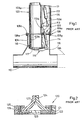
- Fig. 2 illustrates that the seal unit 120 consists of a plate 121 which at its underside is provided with a gasket 122 which is bonded thereto and which is provided with a groove 123 corresponding to and in the assembled condition coinciding with the groove 111b of the flange 108e.
- two rubber mouldings 124 are clamped by means of flat bars 125 and mounting screws 126, said rubber mouldings each having a width substantially exceeding half the width of the plate 121 so that the free edges of the rubber mouldings 124 sealingly engage each other to form an inverted V.
- filling members 127 for instance of epoxy cement, are provided which may suitably be attached by bonding or screwing from below and in a manner not illustrated in detail.
- the seal unit 120 is attached to the flange 108e by means of mounting screws which simultaneously provide additional clamping of the rubber mouldings 124.
- the insertion chute 303 is basically of a unitary structure with integral upper and lower portions 303a and 303b and with a single connecting flange 308a provided on the exterior of the insertion chute 303 at the transition between the upper and lower portions of the insertion chute.
- Said single connecting flange 308a forms the flange joint 308 in cooperation with the connecting flange 308g of the branching.
- the portion of the single flange 308a forming the bottom of the superstructure 311 is provided with a box-like upwardly projecting extension 330, that is consisting of four upstanding walls 331 covered by a firmly connectable but removable lid 332 which, as will be understood, is provided for maintenance and/or repair purposes.
- the flange 308a is also, in its portion not forming the bottom of the superstructure 311, extended upwardly so as to form an outer housing 340 being substantially level with the outer surface of the branching 309, mainly for aesthetical purposes.
- the pivot transmission link 313 is operationally identical to the transmission link according to the prior art, but consists of two more distinct levers 313a, 313b which are furthermore displaced from each other in the direction of the axle journal 333 carrying said transmission link levers. More specifically a first end of said axle journal 333 is pivotally journalled in a suitable bearing 334 - preferably a slide bearing - provided on the inner surface of one of the upstanding walls 331 of the flange extension 330 whereas a midportion of the axle journal 333 is pivotally journalled in a further bearing 335 - likewise preferably a slide bearing - provided in the opposing, upstanding side wall 331 of the flange extension 330.
- the other end of the axle journal 333 that is the end opposite to the first end journalled in the bearing 334, extends through and beyond said last mentioned side wall 331 and carries fixed thereto said one transmission link lever 313a in turn connected to the valve operating means 312.
- axle journal 333 In its portion between the upstanding side walls 331, and therefore between said bearings 334, 335 the axle journal 333 carries said other transmission link lever 313b connected to a conventional connecting or operating rod 314, i.e. there is no need for any specifically configurated operating rod as in the prior art design.
- levers 313a, 313b are fixed to the axle journal 333 which in turn is rotatable in its bearings.
- the flange extension would preferably likewise be provided in the flange of the upper chute portion but could be provided in either of the connecting flanges, with the remaining flanges having corresponding cut-outs for accomodating the extension or the connecting rod and the transmission lever.
Landscapes
- Engineering & Computer Science (AREA)
- Architecture (AREA)
- Civil Engineering (AREA)
- Structural Engineering (AREA)
- Refuse Collection And Transfer (AREA)
- Chutes (AREA)
- Processing Of Solid Wastes (AREA)
Claims (4)
- Freistehender Einwurfschacht (303) der Art, dass mehrere Schächte in regelmäßigen Abstandsintervallen mit einer unterirdischen Saugförderleitung verbunden sind, welche mit einer Abfallsauganlage kommuniziert, wobei das obere Ende jedes Schachts überirdisch eine verschließbare Einwurföffnung umfasst und das untere Ende jedes Schachts unterirdisch mit der Saugförderungsleitung verbunden ist, die mit diesem durch ein in dem Einwurfschacht vorgesehenes Ventilmittel (316) kommuniziert, wobei der Einwurfschacht (303) einen oberen Schachtabschnitt (303a) und einen unteren Schachtabschnitt (303b) umfasst, und zumindest einen Verbindungsflansch (308a) in dem Übergangsbereich zwischen dem oberen Schachtabschnitt (303a) und dem unteren Schachtabschnitt (303b), wobei der untere Schachtabschnitt (303b) in einer Verzweigung (309) aufgenommen wird, welche sich von der Saugförderleitung erstreckt und in ihrem oberen Ende ebenfalls einen Verbindungsflansch (308g) aufweist, wobei der zumindest eine Verbindungsflansch (308a) des Einwurfschachts (303) lösbar mit dem Verbindungsflansch (308g) der Verzweigung (309) verbunden ist und die Verzweigung (309) in Relation zu der Tiefe der Saugförderleitung unterhalb der Bodenfläche eine solche Länge aufweist, dass die von den Verbindungsflanschen (308a, 308b) gebildete Flanschverbindung (308) oberhalb der Bodenfläche (130) positioniert ist, wobei ein gehäuseartiger Aufbau (311) an den oberen Schachtabschnitt angeschweißt und in dem gehäuseartigen Aufbau ein Ventilbetätigungsmittel (312) gelagert ist, wobei das Ventilbetätigungsmittel (312) mit einem Übertragungsglied (313) verbunden ist, mit dem ebenfalls ein Ende einer Betätigungsstange (314) verbunden ist, welche an ihrem anderen Ende mit dem am unteren Ende des unteren Schachtabschnitts (303b) befestigten Ventilmittel (316) verbunden ist,
dadurch gekennzeichnet, dass einer der Verbindungsflansche mit einer aufwärtsgerichteten Verlängerung (330) versehen ist, in der ein Achsgelenk (333) des Übertragungsgliedes (313) drehbar gelagert ist, wobei ein Hebel (313b) des Übertragungsgliedes (313) an dem Achsgelenk im Inneren der Verlängerung (330) befestigt ist und ein anderer Übertragungsgliedhebel (313a) an dem Achsgelenk (333) außerhalb der Verlängerung (330) befestigt ist. - Einwurfschacht nach Anspruch 1,
dadurch gekennzeichnet, dass das Achsgelenk (333) an einem seiner Enden angrenzend an der inneren Oberfläche einer Seitenwand (331) der Verlängerung (330) gelagert ist und sich mit seinem anderen Ende durch und hinter einer gegenüberliegenden Seitenwand (331) der Verlängerung erstreckt, wobei die Übertragungsgliedhebel (313b bzw. 313a) an dem Achsgelenk (333) auf gegenüberliegenden Seiten der anderen Seitenwand (331) der Verlängerung (330) befestigt sind und das Achsgelenk (333) in der anderen Seitenwand (331) durch eine flüssigkeitsdichte Lagerung gelagert ist. - Einwurfschacht nach Anspruch 1 oder 2,
dadurch gekennzeichnet, dass der Einwurfschacht (303) als eine Einheit ausgebildet ist, zusammen mit dem oberen Schachtabschnitt (303a) und dem unteren Schachtabschnitt (303b) als integralem Bestandteil, und dass ein Verbindungsflansch (308a) außerhalb an dem Einwurfschacht (303) an dem Übergang zwischen den oberen und unteren Schachtabschnitten vorgesehen ist. - Einwurfschacht nach Anspruch 1 oder 2,
dadurch gekennzeichnet, dass der Einwurfschacht aus einem separaten oberen Schachtabschnitt besteht, der an seinem unteren Ende mit einem Verbindungsflansch versehen ist, und einem separaten unteren Schachtabschnitt, der an seinem oberen Ende mit einem Verbindungsflansch versehen ist, und dass der Verbindungsflansch des unteren Schachtabschnitts lösbar eingespannt ist zwischen dem Verbindungsflansch des oberen Schachtabschnitts und dem Verbindungsflansch der Verzweigung.
Applications Claiming Priority (3)
| Application Number | Priority Date | Filing Date | Title |
|---|---|---|---|
| KR9532031 | 1995-09-22 | ||
| KR1019950032031A KR100222271B1 (ko) | 1995-09-22 | 1995-09-22 | 분리형 삽입 슈트 |
| PCT/SE1996/001150 WO1997011013A1 (en) | 1995-09-22 | 1996-09-16 | Isolated insertion chute for suction-operated garbage disposal systems |
Publications (2)
| Publication Number | Publication Date |
|---|---|
| EP0958205A1 EP0958205A1 (de) | 1999-11-24 |
| EP0958205B1 true EP0958205B1 (de) | 2005-11-30 |
Family
ID=19427955
Family Applications (1)
| Application Number | Title | Priority Date | Filing Date |
|---|---|---|---|
| EP96932114A Expired - Lifetime EP0958205B1 (de) | 1995-09-22 | 1996-09-16 | Freistehender einwurfschacht für eine abfallsauganlage |
Country Status (5)
| Country | Link |
|---|---|
| EP (1) | EP0958205B1 (de) |
| KR (1) | KR100222271B1 (de) |
| AU (1) | AU7102096A (de) |
| ES (1) | ES2264565T3 (de) |
| WO (1) | WO1997011013A1 (de) |
Families Citing this family (7)
| Publication number | Priority date | Publication date | Assignee | Title |
|---|---|---|---|---|
| SG139522A1 (en) * | 2003-08-04 | 2008-02-29 | Sembcorp Environmental Man Pte | Chute intermediate storage system and method of conveying refuse thereof |
| ES2319482B1 (es) * | 2006-08-03 | 2009-12-18 | Ros Roca S.A. | Valvula simple de vertido polivalente. |
| KR100884812B1 (ko) | 2007-06-28 | 2009-02-20 | 엔백 주식회사 | 쓰레기 자동집하시설의 음식물 쓰레기 수거 시스템 |
| KR100919848B1 (ko) * | 2007-12-03 | 2009-09-30 | 주식회사 신성엔지니어링 | 쓰레기 저류장치 |
| SE532516C2 (sv) * | 2008-06-04 | 2010-02-16 | Logiwaste Ab | Schakt för uppsamlingsanläggning samt sammanhängande enhet för schakt med löstagbart monterad enhet innefattande bl.a. ett ventilorgan |
| KR100865616B1 (ko) * | 2008-06-18 | 2008-10-27 | 주식회사 금호환경기술 | 쓰레기 이송 시스템의 쓰레기 투입단속장치 |
| KR100896398B1 (ko) * | 2009-02-06 | 2009-05-08 | 코오롱건설주식회사 | 쓰레기 수거시스템의 용적 제한형 쓰레기 투입구 |
Family Cites Families (4)
| Publication number | Priority date | Publication date | Assignee | Title |
|---|---|---|---|---|
| US3316026A (en) * | 1965-04-09 | 1967-04-25 | Hallstrom Olof Henrik | Arrangement in refuse disposal chutes |
| SE381021B (sv) * | 1973-02-20 | 1975-11-24 | Centralsug Ab | Mottagningsanleggning for skrep, sopor och liknande avfall |
| US4640403A (en) * | 1985-02-13 | 1987-02-03 | Mcdermott Daniel R | Gravity-conveyor chute section |
| SE461211B (sv) * | 1987-08-17 | 1990-01-22 | Centralsug Ab | Anordning vid fristaaende inkastschakt till en avfallssuganlaeggning |
-
1995
- 1995-09-22 KR KR1019950032031A patent/KR100222271B1/ko not_active Expired - Lifetime
-
1996
- 1996-09-16 EP EP96932114A patent/EP0958205B1/de not_active Expired - Lifetime
- 1996-09-16 AU AU71020/96A patent/AU7102096A/en not_active Abandoned
- 1996-09-16 WO PCT/SE1996/001150 patent/WO1997011013A1/en not_active Ceased
- 1996-09-16 ES ES96932114T patent/ES2264565T3/es not_active Expired - Lifetime
Also Published As
| Publication number | Publication date |
|---|---|
| EP0958205A1 (de) | 1999-11-24 |
| WO1997011013A1 (en) | 1997-03-27 |
| KR970015426A (ko) | 1997-04-28 |
| AU7102096A (en) | 1997-04-09 |
| KR100222271B1 (ko) | 1999-10-01 |
| ES2264565T3 (es) | 2007-01-01 |
Similar Documents
| Publication | Publication Date | Title |
|---|---|---|
| EP0958205B1 (de) | Freistehender einwurfschacht für eine abfallsauganlage | |
| EP0248830A1 (de) | Förderbehälter zur spedition von massengut. | |
| US5004377A (en) | Isolated insertion chute for suction-operated garbage disposal systems | |
| US4469135A (en) | Air entrained particulate material valve | |
| AU1416492A (en) | Element for sealing and monitoring a body, in particular a refuse dump | |
| CN211090273U (zh) | 一种用于电气设备的可翻转式地埋箱及地埋装置 | |
| CN205639703U (zh) | 一种输送粉状物料可调节任意开度的三通阀 | |
| DE59806413D1 (de) | Zellenradschleuse zum Dosieren von Schüttgut | |
| US4548147A (en) | Hopper barge with bottom flaps and a suction channel | |
| FR2747449B1 (fr) | Joint d'etancheite pour une traversee de paroi, procede de realisation d'un tel joint, et assemblage obtenu avec ce joint ou par ce procede | |
| SE521271C3 (de) | ||
| US6273647B1 (en) | Pressure discharge railway hopper car | |
| CN213084302U (zh) | 一种垃圾箱锁紧装置 | |
| CN212203176U (zh) | 一种新型气动锥斗插板阀 | |
| GB2299357A (en) | Access frame | |
| US5402731A (en) | Actuator assembly | |
| US6089530A (en) | Gate valve | |
| CN2297605Y (zh) | 一种三通装置 | |
| CN2179499Y (zh) | 闸板阀 | |
| CN2214968Y (zh) | 带有柔性接口的双45°弯头排水管件 | |
| WO2009148380A1 (en) | Shaft for a collection plant and coherent unit for the shaft with a removably mounted unit comprising, inter alia, a valve means | |
| CN87206455U (zh) | 一种风力输送管道用阀门 | |
| CA1070117A (en) | Proportioning valve | |
| CN208516200U (zh) | 一种垃圾车箱体密封结构 | |
| AU3677599A (en) | Slide valve assembly |
Legal Events
| Date | Code | Title | Description |
|---|---|---|---|
| PUAI | Public reference made under article 153(3) epc to a published international application that has entered the european phase |
Free format text: ORIGINAL CODE: 0009012 |
|
| AK | Designated contracting states |
Kind code of ref document: A1 Designated state(s): ES GR PT SE |
|
| 17P | Request for examination filed |
Effective date: 19980411 |
|
| GRAP | Despatch of communication of intention to grant a patent |
Free format text: ORIGINAL CODE: EPIDOSNIGR1 |
|
| GRAS | Grant fee paid |
Free format text: ORIGINAL CODE: EPIDOSNIGR3 |
|
| GRAA | (expected) grant |
Free format text: ORIGINAL CODE: 0009210 |
|
| AK | Designated contracting states |
Kind code of ref document: B1 Designated state(s): ES GR PT SE |
|
| PG25 | Lapsed in a contracting state [announced via postgrant information from national office to epo] |
Ref country code: GR Free format text: LAPSE BECAUSE OF FAILURE TO SUBMIT A TRANSLATION OF THE DESCRIPTION OR TO PAY THE FEE WITHIN THE PRESCRIBED TIME-LIMIT Effective date: 20060228 |
|
| REG | Reference to a national code |
Ref country code: SE Ref legal event code: TRGR |
|
| REG | Reference to a national code |
Ref country code: PT Ref legal event code: PC4A Owner name: ENVAC CENTRALSUG AB, SE Effective date: 20060313 |
|
| PLBE | No opposition filed within time limit |
Free format text: ORIGINAL CODE: 0009261 |
|
| STAA | Information on the status of an ep patent application or granted ep patent |
Free format text: STATUS: NO OPPOSITION FILED WITHIN TIME LIMIT |
|
| 26N | No opposition filed |
Effective date: 20060831 |
|
| REG | Reference to a national code |
Ref country code: ES Ref legal event code: PC2A |
|
| REG | Reference to a national code |
Ref country code: ES Ref legal event code: FG2A Ref document number: 2264565 Country of ref document: ES Kind code of ref document: T3 |
|
| PGFP | Annual fee paid to national office [announced via postgrant information from national office to epo] |
Ref country code: PT Payment date: 20150818 Year of fee payment: 20 Ref country code: ES Payment date: 20150903 Year of fee payment: 20 |
|
| PGFP | Annual fee paid to national office [announced via postgrant information from national office to epo] |
Ref country code: SE Payment date: 20150924 Year of fee payment: 20 |
|
| REG | Reference to a national code |
Ref country code: SE Ref legal event code: EUG |
|
| PG25 | Lapsed in a contracting state [announced via postgrant information from national office to epo] |
Ref country code: PT Free format text: LAPSE BECAUSE OF EXPIRATION OF PROTECTION Effective date: 20160926 |
|
| REG | Reference to a national code |
Ref country code: ES Ref legal event code: FD2A Effective date: 20161227 |
|
| PG25 | Lapsed in a contracting state [announced via postgrant information from national office to epo] |
Ref country code: ES Free format text: LAPSE BECAUSE OF EXPIRATION OF PROTECTION Effective date: 20160917 |