EP0958090B1 - Schweisssystem und verfahren zum festlegen der schweissparameter für eine schweissstromquelle - Google Patents
Schweisssystem und verfahren zum festlegen der schweissparameter für eine schweissstromquelle Download PDFInfo
- Publication number
- EP0958090B1 EP0958090B1 EP98901240A EP98901240A EP0958090B1 EP 0958090 B1 EP0958090 B1 EP 0958090B1 EP 98901240 A EP98901240 A EP 98901240A EP 98901240 A EP98901240 A EP 98901240A EP 0958090 B1 EP0958090 B1 EP 0958090B1
- Authority
- EP
- European Patent Office
- Prior art keywords
- welding
- data
- current source
- control device
- wire
- Prior art date
- Legal status (The legal status is an assumption and is not a legal conclusion. Google has not performed a legal analysis and makes no representation as to the accuracy of the status listed.)
- Expired - Lifetime
Links
- 238000003466 welding Methods 0.000 title claims description 206
- 238000000034 method Methods 0.000 title claims description 40
- 230000005540 biological transmission Effects 0.000 claims description 5
- 239000000203 mixture Substances 0.000 claims description 3
- 238000012546 transfer Methods 0.000 claims description 3
- 239000000956 alloy Substances 0.000 claims description 2
- 229910045601 alloy Inorganic materials 0.000 claims description 2
- 239000007789 gas Substances 0.000 claims 3
- 239000000969 carrier Substances 0.000 description 9
- 238000006073 displacement reaction Methods 0.000 description 5
- 238000010586 diagram Methods 0.000 description 4
- 230000001681 protective effect Effects 0.000 description 4
- 238000012545 processing Methods 0.000 description 3
- 230000006978 adaptation Effects 0.000 description 2
- 238000011156 evaluation Methods 0.000 description 2
- 230000003213 activating effect Effects 0.000 description 1
- 230000000712 assembly Effects 0.000 description 1
- 238000000429 assembly Methods 0.000 description 1
- 230000004397 blinking Effects 0.000 description 1
- 238000004590 computer program Methods 0.000 description 1
- 238000010276 construction Methods 0.000 description 1
- 238000010891 electric arc Methods 0.000 description 1
- 239000000463 material Substances 0.000 description 1
- 238000012360 testing method Methods 0.000 description 1
- 238000012549 training Methods 0.000 description 1
- 238000005493 welding type Methods 0.000 description 1
Images

Classifications
-
- B—PERFORMING OPERATIONS; TRANSPORTING
- B23—MACHINE TOOLS; METAL-WORKING NOT OTHERWISE PROVIDED FOR
- B23K—SOLDERING OR UNSOLDERING; WELDING; CLADDING OR PLATING BY SOLDERING OR WELDING; CUTTING BY APPLYING HEAT LOCALLY, e.g. FLAME CUTTING; WORKING BY LASER BEAM
- B23K9/00—Arc welding or cutting
- B23K9/32—Accessories
-
- B—PERFORMING OPERATIONS; TRANSPORTING
- B23—MACHINE TOOLS; METAL-WORKING NOT OTHERWISE PROVIDED FOR
- B23K—SOLDERING OR UNSOLDERING; WELDING; CLADDING OR PLATING BY SOLDERING OR WELDING; CUTTING BY APPLYING HEAT LOCALLY, e.g. FLAME CUTTING; WORKING BY LASER BEAM
- B23K9/00—Arc welding or cutting
- B23K9/095—Monitoring or automatic control of welding parameters
-
- B—PERFORMING OPERATIONS; TRANSPORTING
- B23—MACHINE TOOLS; METAL-WORKING NOT OTHERWISE PROVIDED FOR
- B23K—SOLDERING OR UNSOLDERING; WELDING; CLADDING OR PLATING BY SOLDERING OR WELDING; CUTTING BY APPLYING HEAT LOCALLY, e.g. FLAME CUTTING; WORKING BY LASER BEAM
- B23K9/00—Arc welding or cutting
- B23K9/10—Other electric circuits therefor; Protective circuits; Remote controls
Definitions
- the invention relates to a welding system as described in the preamble of claim 1 is.
- a welding system is known from JP-A1 06 023 550, in which a welding current source is used several different additional modules can be connected.
- the additional modules are formed by a welding head or a welding torch, wherein each additional module has an identification unit, via which the Control device electronically recognize the additional modules by a data query can.
- identification cards are used as external storage, on which data is stored for an additional module.
- the control device the welding power source is connected to a mechanical drive, whereby this mechanical drive stores the data stored on the identification cards Data can be read and then sent to the control device be forwarded so that the control of the individual according to this data Components such as the welding torch motors and the control system the welding current source, can be carried out by the control device.
- the disadvantage here is that the user of such a welding system or Such welding system when changing the additional module, in particular the Welding head or the welding torch, a corresponding identification card with must lead, so that after connecting the additional module to the welding machine the user can insert this identification card into the mechanical drive and thus the data can be read from the identification card.
- JP-A1 02 080 186 describes a method for controlling a laser machine known, wherein a hardware-based identification code is read via the laser can be and this code is forwarded to a control device can.
- the object of the invention is a welding device or a welding current source and / or to create an additional module for a welding device and / or a cutting device, with which data can be read in and the parameters for welding and / or cutters or welding current sources can be carried out precisely and quickly can.
- the advantage here is that by reading the special product data from the data carrier of the additional modules through the receiving device and then forwarding the product data to the welding machine or to Welding power source an independent setting of the welding machine or Welding power source is performed, so that operating errors such as this prevented when setting a diameter of a welding wire becomes.
- Another advantage is that, for example, when using special Gas cylinders hazard warnings can be saved on the disk then shown on the display of the welding machine or welding power source and / or reproduced audio, so that a hint to the user the special application or the dangers of this gas bottle can be seen.
- Another advantage is that it makes it easy to read the data from the Data carriers is possible.
- an embodiment according to claim 2 is also advantageous since it makes it easier Data exchange between the additional modules and the control device of the welding machine or the welding current source is possible.
- an embodiment according to claim 4 is also advantageous, since it makes it flawless Data transmission between the recording device and the control device the welding power source is possible.
- an embodiment according to claim 6 is also advantageous, since it provides the additional information can be used for system processing, so that in simple Form a log for a welding process performed by the welding machine or created by a personal computer connected to the welding machine can be.
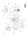
- a welding system 1 for a welding device 2 or a welding current source is shown in FIG or a cutter shown.
- the welding device 2 includes an input and / or output device 3, a control device 4 and a current source 5.
- the input and / or output device 3 is composed of a display device 6 -
- a display and an input device 7, for example, from individual switches 8 and potentiometers 9 are formed for setting the welding parameters will - together.
- the input device 7 enables the user to do this Match welding device 2 to a corresponding welding process, i.e. that the operator Using the switch 8, for example, different welding processes can select, the user using the potentiometer 9 various welding parameters - such as wire diameter, welding current, etc. - can be set.
- the user Set welding parameters are displayed on the display device 6, so that constant control can be carried out by the user.
- a switch 8 is arranged, in which already for the a wide variety of welding processes and a wide variety of welding parameters are, d. that is, by setting a welding process with this switch 8 already the wire diameter or the welding current independently from the control device 4 is specified.
- the control device 4 has the task of the user at the input and / or Output device 3 set welding parameters corresponding to the power source 5 forward.
- the current source 5 has two outputs 10, 11 for one Consumer 12 on. At the output 10 is via a supply line 13 Welding torch 14 connected, while output 11 via a supply line 15 a workpiece 16 is connected.
- the welding device 2 is also connected to a voltage supply network via feed lines 17, 18 19 connected.
- a voltage supply network via feed lines 17, 18 19 connected.
- the welding device 2 both to a two-phase power supply network and to a three-phase power supply network can be connected.
- the additional modules 20 can, for example, by a wire feed device 21 and a gas supply device 22 are formed.
- the wire feeder 21 can be, for example, from an unwinder 23 and a wire roll 24 are formed. From the wire feeder 21 is a welding wire 25 wound up from the wire roll 24 via the welding device 2 and the supply line 13 to the welding torch 14. That is, the user the welding device 2 a welding process with a fusible electrode - that is the welding wire 25 - can perform. Of course it is possible that instead the wire feeder 21 a non-fusible electrode on the welding torch 14 can be arranged, however, the user for the welding process in addition must supply a welding wire 25 by hand.
- the gas supply device 22 can be formed, for example, by a gas bottle 26 become. Of course, it is possible that instead of the gas bottle 26 an in-house gas supply network can be used.
- the feeding of the in of the gas bottle 27 is carried to the welding device 2 via a gas line 28, the gas 27 from the welding device 2 to the welding torch 14 via the supply line 13 can be supplied.
- the Feeding the individual components of the additional modules 20 to the welding torch 14 can be done via separate lines.
- the welding device 2 in particular the control device 4, has an external interface with which the welding device 2 via a data line 29 can be connected to a personal computer 30.
- the welding device 2 must be set for the corresponding welding process.
- the data carrier 31 can for example be formed by a label 32, in particular by a bar code label.
- the data carriers 31 of the individual additional modules 20 have data for the corresponding additional module 20, i.e.
- Wire feed device 21 of the data carrier 31 special data about the alloy or the composition of the welding wire 25 and the welding wire length and contains the wire diameter
- the data carrier 31 for the Gas supply device 22 has specific data for the composition of the gas 27.
- the user can view the data from the data carrier 31 of the individual additional modules 20 Via a recording device 33 arranged in the welding device 2 from the data carriers Read 31 of the additional modules 20.
- the receiving device 33 through a basic module 34 arranged in the welding device 2 and via a connecting cable or cordlessly arranged writing and / or reading device 35 for the Provide the bar code on the label 32.
- the user can use the writing and / or reading device 35, which is connected to the basic module 34 via a connecting cable Read data from the label 32 from the data carrier 31, i.e. that the writing and / or reading device 35 is designed in the form of a barcode scanner, so that by the Bar code included data from the writing and / or reading device 35 and are then implemented by the basic module 34.
- the basic module 34 After the basic module 34 the data of the data carrier 31 into a corresponding one for the control device 4 Has converted form, the basic module 34 transfers the data to the control device 4, whereby a control or setting of the welding device 2 to the corresponding Additional modules 20 takes place. It is possible that the writing and / or Reader 35 is wireless, wherein when connecting the writing and / or Reading device 35 with the welding device 2, the data from the writing and / or reading device 35 are transferred to the control device 4.
- the control device 4 reads the data from the data carriers 31 is displayed on the display device 6 so that the user can check whether a Reading errors occurred when reading the bar code arranged on the label 32 is.
- the user enters the data entered by can change the data carriers 31 by the input device 7, so that one Fine-tuning of the user for the welding process chosen by him can be.
- additional, missing data -from User via the input device 7, such as the desired welding current can be adjusted.
- only special data can be changed by the user via the input device 7.
- control device 4 it is possible for special test programs to run in the control device 4, so that, for example, when arranging two incompatible additional modules 20, for example a special gas 27 with a special welding wire 25, a warning signal can be sent from the control device 4, causing the user attention is drawn to the fact that a welding process with these two components not possible.
- FIG. 2 A further exemplary embodiment of the welding system 1 is shown in FIG. 2.
- An exemplary embodiment shows a block diagram of the welding device 2, wherein the same reference numerals are used for the same parts of the figures described above become.
- the control device 4 is activated, for example, by a microprocessor control 38, an interface 39 and a storage device, in particular a memory 40, are arranged via data lines 41, 42. Furthermore, the components the input and / or output device 3, in particular the display device 6, and the input device 7 and the basic module 34 of the recording device 33 connected to the microprocessor controller 38.
- the receiving device 33 is in turn formed from the basic module 34 and the writing and / or reading device 35, now the writing and / or reading device 35 and the basic module 34 are equipped with a transmitting and / or receiving device 43, 44, so that the user of the welding device 2 can move freely with the writing and / or reading device 35 can and the data of the data carrier 31 arranged on the additional module 20 with can read the writing and / or reading device 35.
- a flow meter 45 for the gas supply device 22 via a Line 46 connected whereby the consumption of the microprocessor controller 38 of the gas 27 can be detected in a welding process.
- Welding device 2 has a displacement sensor 47 for the welding wire 25.
- the displacement sensor 47 is connected to the microprocessor controller 38 via a line 48.
- the control device 4, in particular the microprocessor control 38, is at least Via one or more control line 49 with the current source 5, in particular with one Inverter power source 50 connected.
- the inverter power source 50 is via the leads 17, 18 connected to the power supply network 19, so that for one Welding process of the welding torch 14 and the remaining components of the
- the welding device 2 can be supplied with current and voltage from the current source 5 can.
- the outputs 10, 11 for the welding torch 14 are at the current source 5 and the workpiece 16 arranged, again the welding torch 14 and the Workpiece 16 is connected to the power source 5 via the supply lines 13, 15 are.
- the personal computer 30 via the data line if necessary 29 is connected to the interface 39 of the microprocessor control 38, so that the data stored in the control device 4 via the interface 39 the personal computer 30 are forwarded or that of the personal computer 30 data are transferred to the microprocessor 38 via the data line 29.
- the labels 32 are on the individual additional modules 20, in particular on the wire feed device 21 and the gas supply device 22, the labels 32 arranged.
- the Labels 32 have a magnetic strip 51 so that the writing and / or reading device 35 trained to read magnetic strips or to write magnetic strips have to be.
- the microprocessor control 38 When the user starts up the welding machine 2, i.e. the power source 5 is connected to the voltage supply network 19, the microprocessor control 38 a basic setting for the Welding machine 2 loaded in its main memory so that, if desired, the user carry out a welding process with this setting via the welding torch 14 can.
- the microprocessor controller 38 is loaded so that when an operation is completed or when the welding machine 2 is briefly switched off, e.g. so that Users can then replace an add-on module 20 without any settings to have to continue with the welding process.
- the Control for a welding process takes place so that the microprocessor control 38 controls the current source 5 via the control line 49 in such a way that it is connected to the outputs 10, 11 of the current source 5 to the desired current or voltage Welding torch 14 creates, so that the user a welding process with the corresponding Welding parameters can be carried out.
- the microprocessor control 38 controls the additional modules 20 at the same time.
- the user uses the writing and / or reading device 35 to read the data of the individual additional modules Pick up 20 of the labels 32.
- the data is then saved in Writing and / or reading device 35 buffered and via the transmitting and / or Receiving device 44 sent to the basic module 34.
- the advantage of wireless transmission of data that the user with the writing and / or reading device 35 is not bound to a certain area around the welding device 2, but that this has a higher functional radius for reading the data from the labels 32 is available.
- the basic module 34 can be adapted to the writing and / or reading device 35 used by the user.
- the adaptation of the basic module 34 for the corresponding writing and / or reading device 35 can be implemented in the form of a modular construction.
- the basic module 34 simply pulled out of the welding device 2 and by a corresponding Basic module 34 for the corresponding writing and / or reading device 35 for the Labels 32 inserted into the welding device 2, whereby an independent contact of the basic module 34 with the hardware of the welding device 2.
- the Basic module 34 is designed in such a way that 32 when reading the data from the basic module 34 for the microprocessor control 38 to be converted.
- the advantage here is that a simple exchange and a rapid adaptation to a wide variety of labels 32 can be carried out can be done without the need for additional programming.
- the writing and / or reading device 35 it is also possible for the writing and / or reading device 35 to have an internal memory has, so that the user after reading all the data from the additional module 20 with the writing and / or reading device 35 goes to the welding device 2 and connects them of the writing and / or reading device 35 with the interface 39 to the Control device 4 or passes to the basic module 34.
- transponder system for this welding system 1 can be used.
- the individual additional modules 20 Transponder attached which then by activating the basic module 34 from Welding machine 2 can be detected independently.
- the user does not need a writing and / or reading device 35 because of the basic module 34 a corresponding frequency is sent, which the transponders to the Additional modules 20 activated and a corresponding code or the data that in Transponders are stored, send to the basic module 34, so that an automatic Setting the welding machine 2 is guaranteed.
- the data of the labels 32 are of the basic module 34 converted so that the microprocessor controller 38 can read. It is e.g. possible that the data of the labels 32 by different assignment numbers be formed.
- the basic module 34 transfer individual assignment numbers to the microprocessor control 38. This stores the individual assignment numbers in their main memory, so that afterwards the microprocessor control 38 process the individual assignment numbers can.
- the assignment numbers correspond to addresses for the storage space in memory 40 so that the microprocessor controller 38 stores the data contained in this address range are stored in memory 40, from memory 40 via the data line 41 can be read out. After the microprocessor controller 38 all map numbers has processed, i.e.
- the microprocessor controller 38 can the current source 5 with the resulting Activate the calculated setting for welding machine 2.
- the user in turn via the input device 7, in particular with this arranged switches 8 and potentiometers 9, the missing data for a welding process e.g. can also set the welding current or that the specified Data still displayed on the display device 6 by the user Getting corrected.
- the user can now start the welding process. This will e.g. by touching the welding wire 25 from the welding torch 14 with the workpiece 16 the arc 36 ignited.
- the microprocessor control 38 controls the gas supply device 22 via a control line 52, i.e. that e.g. a valve arranged on the gas supply device via the Control line 52 is activated so that the protective gas atmosphere on the welding torch 14 37 is generated.
- the microprocessor controller 38 controls the processing device via a control line 53 23 of the wire feeder 21.
- the processing device is activated 23 so that according to the one supplied via the control line 53 Voltage a certain wire feed speed is specified.
- the microprocessor control 38 the consumption of the components of the additional modules 20 at all times determine and display them on the display device 6. This is an advantage since the user can determine at any time how much gas 27 is still in the gas bottle 26 or which welding wire length is still on the wire reel 24.
- the Data which are determined via the flow meter 45 and the displacement sensor 47, are buffered in the microprocessor control 38 or are directly in the Memory 40 deposited.
- the welding machine 2 receives the data from the personnel via the interface 39 Computer 30 can retrieve, or that when connecting another welding machine 2 with the personal computer 30, the data from the personal computer 30 automatically to the welding machine 2 when a corresponding assignment number is called up be transmitted.
- the microprocessor controller 38 sends this data hand over the basic module 34.
- the user In order to transmit the data from the basic module 34 to the corresponding additional module 20, the user must first of all assign the corresponding add-on module 20 inquire about the label 32 via the writing and / or reading device 35.
- the writing and / or reading device 35 in turn sends them via the transmitting and / or Receiving device 44 to the basic module 34.
- the basic module 34 compares the assignment numbers so that the basic module 34 those from the microprocessor controller 38 transferred data for this additional module 20 via the transmission and / or send the receiving device 43 to the writing and / or reading device 35 can, which is then stored on the magnetic strip 51 of the additional module 20 can be.
- This procedure is advantageous because it reduces consumption or the remaining content of the individual additional modules 20 are stored, so that when the additional modules 20, e.g. with a half empty quantity Gas bottle 26, another user of another welding machine 2 this gas bottle 26 can use and by reading the data carrier 31, the fill quantity of this additional module 20 can determine.
Landscapes
- Engineering & Computer Science (AREA)
- Physics & Mathematics (AREA)
- Plasma & Fusion (AREA)
- Mechanical Engineering (AREA)
- Arc Welding Control (AREA)
Description
- Fig. 1
- eine schematische Darstellung eines erfindungsgemäßen Schweißsystems, in vereinfachter und schematischer Darstellung;
- Fig. 2
- ein Blockschaltbild einer weiteren Ausführungsform des erfindungsgemäßen Schweißsystems, in vereinfachter und schematischer Darstellung.
- 1
- Schweißsystem
- 2
- Schweißgerät
- 3
- Ein- und/oder Ausgabevorrichtung
- 4
- Steuervorrichtung
- 5
- Stromquelle
- 6
- Anzeigevorrichtung
- 7
- Eingabevorrichtung
- 8
- Schalter
- 9
- Potentiometer
- 10
- Ausgang
- 11
- Ausgang
- 12
- Verbraucher
- 13
- Versorgungsleitung
- 14
- Schweißbrenner
- 15
- Versorgungsleitung
- 16
- Werkstück
- 17
- Zuleitung
- 18
- Zuleitung
- 19
- Spannungsversorgungsnetz
- 20
- Zusatzmodul
- 21
- Drahtzufuhrvorrichtung
- 22
- Gasversorgungsvorrichtung
- 23
- Abwicklungsgerät
- 24
- Drahtrolle
- 25
- Schweißdraht
- 26
- Gasflasche
- 27
- Gas
- 28
- Gasleitung
- 29
- Datenleitung
- 30
- Personal Computer
- 31
- Datenträger
- 32
- Etikette
- 33
- Aufnahmevorrichtung
- 34
- Grundmodul
- 35
- Schreib- und/oder Lesegerät
- 36
- Lichtbogen
- 37
- Schutzgasatmosphäre
- 38
- Mikroprozessorsteuerung
- 39
- Schnittstelle
- 40
- Speicher
- 41
- Datenleitung
- 42
- Datenleitung
- 43
- Sende- und/oder Empfangsvorrichtung
- 44
- Sende- und/oder Empfangsvorrichtung
- 45
- Durchflußmesser
- 46
- Leitung
- 47
- Wegmeßfühler
- 48
- Leitung
- 49
- Steuerleitung
- 50
- Inverterstromquelle
- 51
- Magnetstreifen
- 52
- Steuerleitung
- 53
- Steuerleitung
Claims (10)
- Schweißsystem mit zumindest einer Schweißstromquelle und einem oder mehreren Zusatzmodulen, insbesondere einer Drahtzufuhrvorrichtung in einem Schweißbrenner und einer Gasversorgungsvorrichtung, wobei jedes Zusatzmodul (20), wie z.B. die Drahtzufuhrvorrichtung (21) und/oder die Gasversorgungsvorrichtung (22), einen Datenträger (31) mit den für das jeweilige Zusatzmodul (20) charakteristischen Daten zur Steuerung der Steuervorrichtung (4) des Schweißgerätes (2) in einem definierten Format aufweist, dadurch gekennzeichnet, daß der Datenträger (31) durch eine Etikette (32) gebildet ist, wobei zum Erfassen der Daten des Datenträgers (31) eine Aufnahmevorrichtung (33) vorgesehen ist, wobei die Aufnahmevorrichtung (33) und/oder ein Speicher der Aufnahmevorrichtung mit der Steuervorrichtung (4) des Schweißgerätes (2) leitungsverbunden oder drahtlos angeordnet ist, und die Aufnahmevorrichtung (33) durch ein Schreib- und/oder Lesegerät (35), z.B. für einen Bar-Code, einen Magnetstreifen, gebildet ist.
- Schweißsystem nach einem oder mehreren der vorhergehenden Ansprüche, dadurch gekennzeichnet, daß die Aufnahmevorrichtung (33) und/oder der Speicher die Daten des Datenträgers (31) an die Steuervorrichtung (4) des Schweißgerätes (2) bzw. der Schweißstromquelle zum Festlegen der einzelnen Schweißparameter übergibt und/oder die Daten von der Steuervorrichtung (4) des Schweißgerätes (2) bzw. der Schweißstromquelle auf die einzelnen Datenträger (31) der einzelnen Zusatzmodule (2) schreibt bzw. speichert.
- Schweißsystem nach Anspruch 1, dadurch gekennzeichnet, daß die Aufnahmevorrichtung (33) durch eine Sende- und/oder Empfangsvorrichtung (43, 44), z.B. für ein Transpondersystem, gebildet ist.
- Schweißsystem nach einem oder mehreren der vorhergehenden Ansprüche, dadurch gekennzeichnet, daß die Aufnahmevorrichtung (33) mit der Steuervorrichtung (4) in der Schweißstromquelle verbunden und/oder angeordnet ist.
- Schweißsystem nach einem oder mehreren der vorhergehenden Ansprüche 1 und 2, dadurch gekennzeichnet, daß die Aufnahmevorrichtung (33) über eine Leitungsverbindungsvorrichtung oder einer weiteren Sende- und/oder Empfangsvorrichtung (43, 44) zum Datenaustausch mit der Steuervorrichtung (4) der Schweißstromquelle verbunden ist.
- Schweißsystem nach einem der vorhergehenden Ansprüche, dadurch gekennzeichnet, daß auf dem Datenträger Zusatzinformationen, wie beispielsweise die Länge des Schweißdrahtes (25), die Zusammensetzung des Schweißdrahtes (25) usw. hinterlegt sind.
- Schweißsystem nach einem oder mehreren der vorhergehenden Ansprüche, dadurch gekennzeichnet, daß die Daten an den Datenträgern (31) durch Zuordnungsnummern, insbesondere durch Adressen, gebildet sind und daß in der Steuervorrichtung (4) eine Speichereinheit angeordnet ist, in der für die einzelnen Zuordnungsnummern die speziellen Daten für die Zusatzmodule (20) hinterlegt sind.
- Schweißsystem nach einem oder mehreren der vorhergehenden Ansprüche, dadurch gekennzeichnet, daß in der Speichereinheit für den entsprechenden Datenträger (31), insbesondere dessen Zuordnungsnummern, zusätzliche Informationen, wie z.B. Schutzmaßnahmen für spezielle Gase (27) oder Drahtlegierungen, hinterlegt sind.
- Schweißsystem nach einem oder mehreren der vorhergehenden Ansprüche, dadurch gekennzeichnet, daß die Schweißstromquelle eine Ein- und/oder Ausgabevorrichtung (3) aufweist, mit der Teile des die Daten bzw. der Informationen der Datenträger (31) nach der Übergabe von der Aufnahmevorrichtung (33) an die Steuervorrichtung (4) bearbeitbar und/oder nicht bearbeitbar sind.
- Schweißsystem nach einem oder mehreren der vorhergehenden Ansprüche, dadurch gekennzeichnet, daß die Schweißparameter der Schweißstromquelle für einen Schweißprozeß durch die Daten der Datenträger (31) bzw. der in der Speichervorrichtung hinterlegten Daten bestimmt sind und daß zusätzliche Schweißparameter, z.B. der Schweißstrom, durch die Ein- und/oder Ausgabevorrichtung (3) festlegbar sind.
Applications Claiming Priority (3)
| Application Number | Priority Date | Filing Date | Title |
|---|---|---|---|
| AT18397A AT406460B (de) | 1997-02-06 | 1997-02-06 | Schweisssystem und verfahren zum festlegen der schweissparameter für eine schweissstromquelle |
| AT18397 | 1997-02-06 | ||
| PCT/AT1998/000021 WO1998034751A1 (de) | 1997-02-06 | 1998-02-03 | Schweisssystem und verfahren zum festlegen der schweissparameter für eine schweissstromquelle |
Publications (2)
| Publication Number | Publication Date |
|---|---|
| EP0958090A1 EP0958090A1 (de) | 1999-11-24 |
| EP0958090B1 true EP0958090B1 (de) | 2001-05-02 |
Family
ID=3483699
Family Applications (1)
| Application Number | Title | Priority Date | Filing Date |
|---|---|---|---|
| EP98901240A Expired - Lifetime EP0958090B1 (de) | 1997-02-06 | 1998-02-03 | Schweisssystem und verfahren zum festlegen der schweissparameter für eine schweissstromquelle |
Country Status (6)
| Country | Link |
|---|---|
| EP (1) | EP0958090B1 (de) |
| AT (1) | AT406460B (de) |
| AU (1) | AU5740698A (de) |
| DE (1) | DE59800667D1 (de) |
| ES (1) | ES2158666T3 (de) |
| WO (1) | WO1998034751A1 (de) |
Families Citing this family (21)
| Publication number | Priority date | Publication date | Assignee | Title |
|---|---|---|---|---|
| AT407023B (de) * | 1997-09-09 | 2000-11-27 | Fronius Schweissmasch | Steuervorrichtung zum steuern eines schweissgerätes sowie ein verfahren hierfür |
| US6130407A (en) * | 1998-07-29 | 2000-10-10 | Tregaskiss, Ltd. | Arc welding torch |
| AT407019B (de) * | 1999-01-27 | 2000-11-27 | Fronius Schweissmasch | Schweissbrenner und zugehörige schweissanlage sowie verfahren zur gegenseitigen anpassung |
| AT409601B (de) | 1999-11-02 | 2002-09-25 | Fronius Schweissmasch Prod | Verfahren zur datenübertragung und/oder synchronisierung zwischen zumindest zwei schweissgeräten und die vorrichtung hierzu |
| AT411443B (de) * | 2001-02-16 | 2004-01-26 | Fronius Schweissmasch Prod | Schweissgerät bzw. schweissanlage |
| DE10124805A1 (de) * | 2001-05-22 | 2002-12-12 | Binzel Alex Schweisstech | Drahtvorschubeinheit |
| DE10136994A1 (de) * | 2001-07-23 | 2003-02-06 | Emhart Llc Newark | Fügesystem zum Fügen von Elementen auf Bauteile, Verfahren zum Betreiben eines Fügesystems und Datenspeicher |
| US7084371B2 (en) | 2001-07-23 | 2006-08-01 | Newfrey Llc | Joining system for joining elements onto components, method of operating a joining system and data memory |
| FR2836641A1 (fr) * | 2002-03-04 | 2003-09-05 | Soudure Autogene Francaise | Systeme d'aide au reglage pour poste de soudage mig-mag a commutateur |
| US10144080B2 (en) | 2005-08-25 | 2018-12-04 | Lincoln Global, Inc. | Torch for electric arc welding or plasma cutting system |
| US8431862B2 (en) * | 2005-08-25 | 2013-04-30 | Lincoln Global, Inc. | Torch for electric arc welding system |
| WO2008106419A2 (en) * | 2007-02-27 | 2008-09-04 | Illinois Tool Works Inc. | Structural welding system |
| US20080203075A1 (en) | 2007-02-27 | 2008-08-28 | Feldhausen Joseph E | Portable structural welding system having integrated resources |
| DE102008054172A1 (de) * | 2008-10-31 | 2010-05-06 | Linde Ag | Verfahren zum Lichtbogenschweißen mit abschmelzender Elektrode |
| DE212010000062U1 (de) | 2009-05-18 | 2012-01-10 | Fronius International Gmbh | Fahrwagen für ein Schweißgerät |
| US8445816B2 (en) * | 2009-11-13 | 2013-05-21 | Lincoln Global, Inc. | Modular process list for welding power supply |
| US9511444B2 (en) * | 2011-07-15 | 2016-12-06 | Illinois Tool Works Inc. | Digital communication based arc control welding system and method |
| CN103028816B (zh) * | 2012-12-24 | 2015-10-21 | 上海电机学院 | 基于结构光双目视觉传感的焊接装置的焊接方法 |
| AT514318B1 (de) | 2013-09-12 | 2014-12-15 | Fronius Int Gmbh | Verfahren zum Durchführen eines Schweißprozesses, Schweißgerät und Drahtrolle für ein solches Schweißgerät |
| RU2696121C1 (ru) * | 2018-07-13 | 2019-07-31 | федеральное государственное бюджетное образовательное учреждение высшего образования "Нижегородский государственный технический университет им. Р.Е. Алексеева" (НГТУ) | Способ 3D печати на оборудовании с ЧПУ с интеллектуальной оптимизацией режимов |
| US12275101B2 (en) | 2020-04-08 | 2025-04-15 | Illinois Tool Works Inc. | Smart spool detection for welding-type systems |
Family Cites Families (2)
| Publication number | Priority date | Publication date | Assignee | Title |
|---|---|---|---|---|
| JP2587473B2 (ja) * | 1988-09-17 | 1997-03-05 | 日本電気株式会社 | レーザ加工機の制御方法 |
| JPH0623550A (ja) * | 1992-07-08 | 1994-02-01 | Toshiba Corp | 自動溶接装置 |
-
1997
- 1997-02-06 AT AT18397A patent/AT406460B/de not_active IP Right Cessation
-
1998
- 1998-02-03 WO PCT/AT1998/000021 patent/WO1998034751A1/de not_active Ceased
- 1998-02-03 AU AU57406/98A patent/AU5740698A/en not_active Abandoned
- 1998-02-03 EP EP98901240A patent/EP0958090B1/de not_active Expired - Lifetime
- 1998-02-03 DE DE59800667T patent/DE59800667D1/de not_active Expired - Lifetime
- 1998-02-03 ES ES98901240T patent/ES2158666T3/es not_active Expired - Lifetime
Also Published As
| Publication number | Publication date |
|---|---|
| ES2158666T3 (es) | 2001-09-01 |
| DE59800667D1 (de) | 2001-06-07 |
| ATA18397A (de) | 1999-10-15 |
| AU5740698A (en) | 1998-08-26 |
| EP0958090A1 (de) | 1999-11-24 |
| WO1998034751A1 (de) | 1998-08-13 |
| AT406460B (de) | 2000-05-25 |
Similar Documents
| Publication | Publication Date | Title |
|---|---|---|
| AT406460B (de) | Schweisssystem und verfahren zum festlegen der schweissparameter für eine schweissstromquelle | |
| EP0132528B2 (de) | Werkzeug oder Werkzeughalter, insbesondere für die zerspanende Bearbeitung auf numerisch gesteuerten Bearbeitungszentren | |
| EP2860597B1 (de) | Verfahren zum Erstellen eines zweidimensionalen Mustercodes | |
| DE3872901T2 (de) | Identifikationssystem und verfahren zum schreiben von daten in einem identifikationssystem. | |
| DE3718215A1 (de) | Datenverarbeitungsanordnung eines fertigungs-automationssystems | |
| DE2720480A1 (de) | Mikrocomputer fuer eine materialhandhabungsanlage | |
| DE102021101497A1 (de) | Kabelverarbeitungscenter | |
| DE102004054816A1 (de) | Verfahren und System zur Übertragung eines Bearbeitungsprogramms | |
| EP0801388A1 (de) | Editieranordnung | |
| DE3719817C2 (de) | ||
| EP1678663B1 (de) | Verfahren und vorrichtung zum bereitstellen von karten | |
| EP0491712B1 (de) | Wetterballonsondensendersystem | |
| EP0570752B1 (de) | Verfahren zur Steuerung der Abfrage bzw. Änderung von Betriebsparametern einer programmgesteuerten elektrischen Einrichtung | |
| EP4139078B1 (de) | Verfahren zum betreiben und steuern einer laservorrichtung für das gravieren, markieren, beschriften und/oder schneiden eines vorzugsweisen flachen werkstückes | |
| DE69513435T2 (de) | Zusammentragmaschine und Verfahren zur Steuerung der Maschine | |
| EP0109574B1 (de) | Anordnung zum Darstellen von Texten | |
| DE19839564A1 (de) | Barcodeleser | |
| DE10351929A1 (de) | Vorrichtung und Verfahren zur automatisierten Durchführung von Gaseanwendungen | |
| DE2101586A1 (de) | Datenaufzeichnungssystem fur Magnet karten | |
| DE3607723C1 (de) | Einrichtung und Verfahren zum Ausgeben von alphanumerischen und/oder graphischen Zeichen | |
| DE4102197A1 (de) | Ein system und verfahren zur kontrolle einer gemeinsam verwendeten datenstation durch verwendung einer speicherkarte | |
| DE3531499C2 (de) | ||
| DE1817913C2 (de) | Einrichtung zum Steuern des Durchlaufs von Werkstücken durch eine Transferstraße | |
| DE3234959A1 (de) | Schaltung zum ueberwachen des funktionsablaufes von numerisch gesteuerten (nc) maschinen | |
| DE9319847U1 (de) | Anordnung zur Steuerung eines mehrere Arbeitsgänge umfassenden Fertigungsablaufs |
Legal Events
| Date | Code | Title | Description |
|---|---|---|---|
| PUAI | Public reference made under article 153(3) epc to a published international application that has entered the european phase |
Free format text: ORIGINAL CODE: 0009012 |
|
| 17P | Request for examination filed |
Effective date: 19990805 |
|
| AK | Designated contracting states |
Kind code of ref document: A1 Designated state(s): BE CH DE DK ES FI FR GB GR IE IT LI LU NL PT SE |
|
| AX | Request for extension of the european patent |
Free format text: SI PAYMENT 19990805 |
|
| RAP1 | Party data changed (applicant data changed or rights of an application transferred) |
Owner name: FRONIUS SCHWEISSMASCHINEN PRODUKTION GMBH & CO. KG |
|
| GRAG | Despatch of communication of intention to grant |
Free format text: ORIGINAL CODE: EPIDOS AGRA |
|
| GRAG | Despatch of communication of intention to grant |
Free format text: ORIGINAL CODE: EPIDOS AGRA |
|
| GRAH | Despatch of communication of intention to grant a patent |
Free format text: ORIGINAL CODE: EPIDOS IGRA |
|
| 17Q | First examination report despatched |
Effective date: 20000912 |
|
| GRAH | Despatch of communication of intention to grant a patent |
Free format text: ORIGINAL CODE: EPIDOS IGRA |
|
| GRAA | (expected) grant |
Free format text: ORIGINAL CODE: 0009210 |
|
| AK | Designated contracting states |
Kind code of ref document: B1 Designated state(s): BE CH DE DK ES FI FR GB GR IE IT LI LU NL PT SE |
|
| AX | Request for extension of the european patent |
Free format text: SI PAYMENT 19990805 |
|
| PG25 | Lapsed in a contracting state [announced via postgrant information from national office to epo] |
Ref country code: NL Free format text: LAPSE BECAUSE OF FAILURE TO SUBMIT A TRANSLATION OF THE DESCRIPTION OR TO PAY THE FEE WITHIN THE PRESCRIBED TIME-LIMIT Effective date: 20010502 Ref country code: IE Free format text: LAPSE BECAUSE OF FAILURE TO SUBMIT A TRANSLATION OF THE DESCRIPTION OR TO PAY THE FEE WITHIN THE PRESCRIBED TIME-LIMIT Effective date: 20010502 |
|
| REG | Reference to a national code |
Ref country code: CH Ref legal event code: EP |
|
| REF | Corresponds to: |
Ref document number: 59800667 Country of ref document: DE Date of ref document: 20010607 |
|
| REG | Reference to a national code |
Ref country code: IE Ref legal event code: FG4D Free format text: GERMAN |
|
| REG | Reference to a national code |
Ref country code: CH Ref legal event code: NV Representative=s name: ABP PATENTMARKETING GMBH * ABP PATENTMARKETING GMB |
|
| ITF | It: translation for a ep patent filed | ||
| PG25 | Lapsed in a contracting state [announced via postgrant information from national office to epo] |
Ref country code: PT Free format text: LAPSE BECAUSE OF FAILURE TO SUBMIT A TRANSLATION OF THE DESCRIPTION OR TO PAY THE FEE WITHIN THE PRESCRIBED TIME-LIMIT Effective date: 20010802 Ref country code: DK Free format text: LAPSE BECAUSE OF FAILURE TO SUBMIT A TRANSLATION OF THE DESCRIPTION OR TO PAY THE FEE WITHIN THE PRESCRIBED TIME-LIMIT Effective date: 20010802 |
|
| PG25 | Lapsed in a contracting state [announced via postgrant information from national office to epo] |
Ref country code: GR Free format text: LAPSE BECAUSE OF FAILURE TO SUBMIT A TRANSLATION OF THE DESCRIPTION OR TO PAY THE FEE WITHIN THE PRESCRIBED TIME-LIMIT Effective date: 20010803 |
|
| GBT | Gb: translation of ep patent filed (gb section 77(6)(a)/1977) |
Effective date: 20010726 |
|
| REG | Reference to a national code |
Ref country code: ES Ref legal event code: FG2A Ref document number: 2158666 Country of ref document: ES Kind code of ref document: T3 |
|
| NLV1 | Nl: lapsed or annulled due to failure to fulfill the requirements of art. 29p and 29m of the patents act | ||
| ET | Fr: translation filed | ||
| REG | Reference to a national code |
Ref country code: GB Ref legal event code: IF02 |
|
| PG25 | Lapsed in a contracting state [announced via postgrant information from national office to epo] |
Ref country code: LU Free format text: LAPSE BECAUSE OF NON-PAYMENT OF DUE FEES Effective date: 20020203 |
|
| REG | Reference to a national code |
Ref country code: IE Ref legal event code: FD4D |
|
| PG25 | Lapsed in a contracting state [announced via postgrant information from national office to epo] |
Ref country code: BE Free format text: LAPSE BECAUSE OF NON-PAYMENT OF DUE FEES Effective date: 20020228 |
|
| PLBE | No opposition filed within time limit |
Free format text: ORIGINAL CODE: 0009261 |
|
| STAA | Information on the status of an ep patent application or granted ep patent |
Free format text: STATUS: NO OPPOSITION FILED WITHIN TIME LIMIT |
|
| 26N | No opposition filed | ||
| BERE | Be: lapsed |
Owner name: FRONIUS SCHWEISSMASCHINEN PRODUKTION G.M.B.H. & C Effective date: 20020228 |
|
| REG | Reference to a national code |
Ref country code: CH Ref legal event code: PUE Owner name: FRONIUS INTERNATIONAL GMBH Free format text: FRONIUS SCHWEISSMASCHINEN PRODUKTION GMBH & CO. KG#NR. 89#4643 PETTENBACH (AT) -TRANSFER TO- FRONIUS INTERNATIONAL GMBH#NR. 319#4643 PETTENBACH (AT) Ref country code: CH Ref legal event code: NV Representative=s name: ABP PATENT NETWORK SWISS GMBH |
|
| REG | Reference to a national code |
Ref country code: GB Ref legal event code: 732E |
|
| REG | Reference to a national code |
Ref country code: FR Ref legal event code: TP |
|
| REG | Reference to a national code |
Ref country code: CH Ref legal event code: PFA Owner name: FRONIUS INTERNATIONAL GMBH Free format text: FRONIUS INTERNATIONAL GMBH#NR. 319#4643 PETTENBACH (AT) -TRANSFER TO- FRONIUS INTERNATIONAL GMBH#NR. 319#4643 PETTENBACH (AT) |
|
| REG | Reference to a national code |
Ref country code: ES Ref legal event code: PC2A |
|
| PGFP | Annual fee paid to national office [announced via postgrant information from national office to epo] |
Ref country code: SE Payment date: 20110224 Year of fee payment: 14 Ref country code: CH Payment date: 20110228 Year of fee payment: 14 Ref country code: FI Payment date: 20110221 Year of fee payment: 14 |
|
| REG | Reference to a national code |
Ref country code: CH Ref legal event code: PL |
|
| PG25 | Lapsed in a contracting state [announced via postgrant information from national office to epo] |
Ref country code: LI Free format text: LAPSE BECAUSE OF NON-PAYMENT OF DUE FEES Effective date: 20120229 Ref country code: SE Free format text: LAPSE BECAUSE OF NON-PAYMENT OF DUE FEES Effective date: 20120204 Ref country code: FI Free format text: LAPSE BECAUSE OF NON-PAYMENT OF DUE FEES Effective date: 20120203 Ref country code: CH Free format text: LAPSE BECAUSE OF NON-PAYMENT OF DUE FEES Effective date: 20120229 |
|
| REG | Reference to a national code |
Ref country code: FR Ref legal event code: PLFP Year of fee payment: 19 |
|
| PGFP | Annual fee paid to national office [announced via postgrant information from national office to epo] |
Ref country code: IT Payment date: 20160224 Year of fee payment: 19 Ref country code: ES Payment date: 20160321 Year of fee payment: 19 |
|
| PGFP | Annual fee paid to national office [announced via postgrant information from national office to epo] |
Ref country code: GB Payment date: 20160226 Year of fee payment: 19 Ref country code: FR Payment date: 20160229 Year of fee payment: 19 |
|
| PGFP | Annual fee paid to national office [announced via postgrant information from national office to epo] |
Ref country code: DE Payment date: 20160502 Year of fee payment: 19 |
|
| REG | Reference to a national code |
Ref country code: DE Ref legal event code: R119 Ref document number: 59800667 Country of ref document: DE |
|
| GBPC | Gb: european patent ceased through non-payment of renewal fee |
Effective date: 20170203 |
|
| REG | Reference to a national code |
Ref country code: FR Ref legal event code: ST Effective date: 20171031 |
|
| PG25 | Lapsed in a contracting state [announced via postgrant information from national office to epo] |
Ref country code: DE Free format text: LAPSE BECAUSE OF NON-PAYMENT OF DUE FEES Effective date: 20170901 Ref country code: FR Free format text: LAPSE BECAUSE OF NON-PAYMENT OF DUE FEES Effective date: 20170228 |
|
| PG25 | Lapsed in a contracting state [announced via postgrant information from national office to epo] |
Ref country code: GB Free format text: LAPSE BECAUSE OF NON-PAYMENT OF DUE FEES Effective date: 20170203 Ref country code: IT Free format text: LAPSE BECAUSE OF NON-PAYMENT OF DUE FEES Effective date: 20170203 |
|
| REG | Reference to a national code |
Ref country code: ES Ref legal event code: FD2A Effective date: 20180507 |
|
| PG25 | Lapsed in a contracting state [announced via postgrant information from national office to epo] |
Ref country code: ES Free format text: LAPSE BECAUSE OF NON-PAYMENT OF DUE FEES Effective date: 20170204 |