EP0957751B1 - Optical oximeter probe adapter - Google Patents
Optical oximeter probe adapter Download PDFInfo
- Publication number
- EP0957751B1 EP0957751B1 EP96945005A EP96945005A EP0957751B1 EP 0957751 B1 EP0957751 B1 EP 0957751B1 EP 96945005 A EP96945005 A EP 96945005A EP 96945005 A EP96945005 A EP 96945005A EP 0957751 B1 EP0957751 B1 EP 0957751B1
- Authority
- EP
- European Patent Office
- Prior art keywords
- probe
- terminal
- adapter
- lead
- oximeter
- Prior art date
- Legal status (The legal status is an assumption and is not a legal conclusion. Google has not performed a legal analysis and makes no representation as to the accuracy of the status listed.)
- Expired - Lifetime
Links
- 239000000523 sample Substances 0.000 title claims abstract description 153
- 230000003287 optical effect Effects 0.000 title claims description 9
- 230000003213 activating effect Effects 0.000 claims description 10
- 230000009977 dual effect Effects 0.000 claims description 9
- 230000008878 coupling Effects 0.000 description 8
- 238000010168 coupling process Methods 0.000 description 8
- 238000005859 coupling reaction Methods 0.000 description 8
- QVGXLLKOCUKJST-UHFFFAOYSA-N atomic oxygen Chemical compound [O] QVGXLLKOCUKJST-UHFFFAOYSA-N 0.000 description 6
- 229910052760 oxygen Inorganic materials 0.000 description 6
- 239000001301 oxygen Substances 0.000 description 6
- 239000008280 blood Substances 0.000 description 4
- 210000004369 blood Anatomy 0.000 description 4
- 238000004519 manufacturing process Methods 0.000 description 4
- 230000004044 response Effects 0.000 description 4
- 238000012544 monitoring process Methods 0.000 description 2
- 230000008901 benefit Effects 0.000 description 1
- 238000010586 diagram Methods 0.000 description 1
- 230000005611 electricity Effects 0.000 description 1
- 210000002615 epidermis Anatomy 0.000 description 1
- 238000002955 isolation Methods 0.000 description 1
- 230000031700 light absorption Effects 0.000 description 1
- 230000007246 mechanism Effects 0.000 description 1
- 230000004060 metabolic process Effects 0.000 description 1
- 238000004806 packaging method and process Methods 0.000 description 1
- 210000003491 skin Anatomy 0.000 description 1
- 230000003595 spectral effect Effects 0.000 description 1
- 238000001356 surgical procedure Methods 0.000 description 1
- 230000002123 temporal effect Effects 0.000 description 1
Images


Classifications
-
- A—HUMAN NECESSITIES
- A61—MEDICAL OR VETERINARY SCIENCE; HYGIENE
- A61B—DIAGNOSIS; SURGERY; IDENTIFICATION
- A61B5/00—Measuring for diagnostic purposes; Identification of persons
- A61B5/145—Measuring characteristics of blood in vivo, e.g. gas concentration or pH-value ; Measuring characteristics of body fluids or tissues, e.g. interstitial fluid or cerebral tissue
- A61B5/1455—Measuring characteristics of blood in vivo, e.g. gas concentration or pH-value ; Measuring characteristics of body fluids or tissues, e.g. interstitial fluid or cerebral tissue using optical sensors, e.g. spectral photometrical oximeters
- A61B5/14551—Measuring characteristics of blood in vivo, e.g. gas concentration or pH-value ; Measuring characteristics of body fluids or tissues, e.g. interstitial fluid or cerebral tissue using optical sensors, e.g. spectral photometrical oximeters for measuring blood gases
-
- A—HUMAN NECESSITIES
- A61—MEDICAL OR VETERINARY SCIENCE; HYGIENE
- A61B—DIAGNOSIS; SURGERY; IDENTIFICATION
- A61B2560/00—Constructional details of operational features of apparatus; Accessories for medical measuring apparatus
- A61B2560/04—Constructional details of apparatus
- A61B2560/0443—Modular apparatus
- A61B2560/045—Modular apparatus with a separable interface unit, e.g. for communication
-
- A—HUMAN NECESSITIES
- A61—MEDICAL OR VETERINARY SCIENCE; HYGIENE
- A61B—DIAGNOSIS; SURGERY; IDENTIFICATION
- A61B2562/00—Details of sensors; Constructional details of sensor housings or probes; Accessories for sensors
- A61B2562/08—Sensors provided with means for identification, e.g. barcodes or memory chips
-
- G—PHYSICS
- G01—MEASURING; TESTING
- G01N—INVESTIGATING OR ANALYSING MATERIALS BY DETERMINING THEIR CHEMICAL OR PHYSICAL PROPERTIES
- G01N35/00—Automatic analysis not limited to methods or materials provided for in any single one of groups G01N1/00 - G01N33/00; Handling materials therefor
- G01N35/00584—Control arrangements for automatic analysers
- G01N35/00722—Communications; Identification
- G01N35/00732—Identification of carriers, materials or components in automatic analysers
Definitions
- This invention relates in general to optical oximeters and relates more particularly to an adaptor that enables an optical oximeter probe, that is to say, one designed or configured to be utilized on an associated oximeter monitor, to be used on a different oximeter monitor that normally ulitizes a different probe configuration.
- Noninvasive oximeters have been developed that direct light through a patient's skin into a region, such as a finger, containing arterial blood. This light typically contains two or more primary wavelengths of light. Examples of such oximeters are disclosed in US-A-5,209,230 and US-A-4,700,708.
- the oximeter in US-A-4,700,708 includes a probe that contains a resistor having a resistance that can be measured by a monitor to which the probe is attached.
- the measured valve of the resistance is indicative of the wavelengths of the light directed from the light emitting diodes (LED'S) through the patient's epidermis.
- the monitor uses this information and the measured intensities of light detected at those wavelengths to calculate the blood arterial oxygen content of the patient.
- the LED's are activated in non-overlapping temporal intervals, so that the amount of absorption of light at each of these two wavelengths is measured separately.
- Optical probes can be electrically configured in a plurality of ways.
- US-A-5,249,576 illustrates two configurations of a red light emitting diode (LED) and an infrared LED that emit light into a patient's finger. These two prior art configurations are illustrated in Figures 1 and 2.
- Figure 1 shows a probe configuration 10 in which a pair of LEDs 11 and 12 are connected in a "3-lead configuration" 13 in which the two LED anodes are connected to a terminal 14 and in which the two LED cathodes are each connected to uniquely associated leads 15 and 16.
- This probe also includes: a photodetector 17 that detects light emitted from LEDs 11 and 12; and a resistor 18 having a resistance which is indicative of the wavelength of light produced by at least one of LEDs 11 and 12 (alternately, the resistance can indicate other or additional parameters).
- a probe having a 3-lead configuration of LEDs will be referred to herein as a "3-lead probe" 10.
- the leads to the LEDs 14, 16, and 15 are indicated as ground.
- the VO1 and VO2 designations indicate these are the first and second LED drive voltage leads for oximeters made by other than Nellcor, the assignee of this application.
- the "O" in the VO1 and VO2 terms is intended to refer to “other.” Thus, this probe is sometimes referred to as an "other probe.”
- two LEDs 21 and 22 are connected in a "2-lead configuration" 23 in which the anode of first LED 21 and the cathode of a second LED 22 are connected to a first lead 24, and the cathode of the first LED 21 and the anode of the second LED 22 are connected to a second lead 25.
- This probe also includes a photodetector 26 and a resistor 27 (or other type of mechanism which is indicative of the wavelength produced by one or both LEDs, and/or other parameters).
- a probe having a 2-lead configuration of LEDs will be referred to herein as a "2-lead probe 20".
- the leads to the LEDs are indicated as VN1, and VN2, corresponding to the Nellcor probe first and second voltage signals. This type of probe is also sometimes referred to as a "Nellcor probe.”
- An oximeter monitor that is designed to utilize a probe having the 2-lead configuration of LEDs will be referred to herein as an "2-lead monitor” or “Nellcor oximeter monitor.”
- an oximeter monitor that is designed to utilize a probe having the 3-lead configuration of LEDs will be referred to herein as a “3-lead monitor” or “other oximeter monitor.”
- Some oximeter probes may use one or more additional LEDs. For instance, a second red LED is sometimes used in combination with the first red LED to achieve more balanced light levels.
- the total cost of these probes also includes the indirect costs incurred by hospitals that use both types of probes so that such hospitals also bear the increased costs associated with the smaller volume orders of each type of probe, the cost of stocking multiple different types of probes and the costs of interacting with multiple vendors. All of these factors significantly increase the cost of monitoring patient oxygen saturation.
- US-A-5249576 discussed above addresses this problem by presenting a probe that can be configured to work with any oximeter.
- the photodetector and light sources within this probe are mounted without any interconnections, and a cable interconnects these elements into various configurations by means of appropriately inserted jumper leads.
- this structure enables this probe to be adapted for a wide variety of oximeters, it does not allow any way for a probe which already has its electrical elements interconnected to be used with any arbitrarily selected oximeter.
- an adapter for connecting an optical oximeter to a probe one of which being a three terminal device and the other being a two terminal device see claim 1, said probe having at least first and second light emitters said adapter comprising:
- the present invention therefore provides an adapter which actively connects a 2-lead oximeter probe or monitor to a 3-lead monitor or probe. This is done actively, with the alternating drive signals from the oximeter monitor providing a control signal for switching the adapter connections.
- the adapter connections are preferably made with diodes, transistors, or other active devices.
- the adapter of the present invention thus first connects the 2 leads of the 2-lead device between the first and second terminals of the 3-lead device while a first light emitter is activated, and then connects the 2 leads between the second and third terminals of the 3-lead device.
- the 3-lead device can be either the oximeter monitor or the oximeter probe.
- one of the two drive terminals (VO1, VO2) is active at a time, with the other drive terminal being in a high impedance state, and the third terminal connected to ground. In such a configuration, the adapter does not need to disconnect the other drive terminal.
- the second drive terminal is not in a high impedance state.
- one adapter according to the present invention provides an extra switch to isolate this second drive terminal which is not being used. In one embodiment, this provides a four-transistor switch embodiment, rather than a two-transistor switch or two-diode embodiment.
- two types of adapters are presented that are specially adapted to enable an oximeter probe to be utilized with an oximeter monitor with which it would otherwise be unable to be utilized. These two types of adapters are particularly useful because they enable two widely utilized types of oximeter probes to be utilized on both of their associated types of oximeter monitors.
- the adapters in accordance with the invention are preferably either mounted on the monitor or in a cable used to connect a probe to a monitor, so that each adapter can become an extension of the oximeter itself and can be used by many different patients and can be used by each patient many times.
- the present invention also provides a dual-use probe for use with a plurality of pulse oximeters, comprising:
- the LEDs are preferably not interconnected inside the probe itself, allowing it to be dual-use since the interconnections can be done externally to provide the particular configuration required for the monitor being used.
- the LEDs rather than duplicating all LEDs preferably only the IR LED is reproduced, with a common connector for all the LEDs allowing the red LED to be used for both types of monitors, with only one or the other of the IR LEDs being connected or used.
- Unlike US-A-524,9576 only three LED leads are required to allow the probe to be connected to either a 2 lead or 3 lead oximeter.
- the present invention provides a cable for connecting an oximeter to a probe, either of which can be either of a two-terminal or a three-terminal device, comprising two three-terminal connectors and two two-terminal connectors for respective connection to one each of the oximeter and probe, and two adapters as claimed in any of claims 1 to 8 interconnecting respective pairs of said two and three-terminal connectors
- This monitor is designed to drive a pair of LEDs that are connected in the 3 lead configuration, discussed above in which:
- This type of monitor therefore has the following three terminals for coupling to this type of probe: a first terminal for coupling to the cathode of the first of these two LEDs; a second terminal for coupling to the cathode of the second of these two LEDs; and a third terminal for coupling to both anodes.
- a first terminal for coupling to the cathode of the first of these two LEDs
- a second terminal for coupling to the cathode of the second of these two LEDs
- a third terminal for coupling to both anodes.
- 2-Lead Nellcor Monitor In the second of these two types of oximeter monitors, the monitor is designed and adapted to drive a pair of LEDs connected in the 2-lead configuration in which:
- This type of monitor therefore has the following two terminals for coupling to this type of probe: a first terminal for coupling to the first lead; and a second terminal for coupling to the second lead.
- the 2 LEDs may have the anode of one LED connected to the cathode of the other LED for the common (ground) terminal.
- the two cathodes could be connected to the common terminal, rather than the two anodes.
- a first type of adapter is presented that enables a 3-lead oximeter monitor to drive an oximeter probe having a 2-lead configuration of two LEDs.
- This type of adapter will be referred to herein as a "3-to-2-Type Adapter”.
- a second type of adapter is also presented that enables a 2-lead oximeter monitor to drive an oximeter probe having a 3-lead configuration of two LEDs.
- This type of adapter will be referred to herein as a "2-to-3-Type Adapter".
- these two adapters enable each of these two types of oximeter monitors to be utilized with both of these two types of oximeter probes.
- the adapter can be mounted at a number of different points in the electrical path from the monitor to the probe.
- it can be mounted: within the monitor, externally on a front panel of the monitor, within the cable connecting the probe to the monitor, in the connector at the monitor end of the cable, or at the connector to the probe.
- the adapter has the form of a double-pole, double-throw (DPDT) switch, that is actively switched in response to at least one of the LED drive signals from the monitor.
- DPDT double-pole, double-throw
- a 3-to-2-type adapter can be implemented by any structure that converts a pair of LED drive signals VO1 and VO2 into a pair of LED drive signals VN1 and VN2.
- a 2-to-3-type adapter can be implemented by any structure that converts a pair of LED drive signals VN 1 and VN2 into a pair of LED drive signals VO1 and VO2.
- a 3-to-2-type adapter must convert LED drive signals from a 3-lead monitor into LED drive signals required by a 2-lead probe and a 2-to-3-type adapter must convert LED drive signals from a 2-lead monitor into LED drive signals required by a 3-lead probe.
- the following two sections describe particular examples of these two sets of probes, monitors, and signals.
- a 3-lead monitor 51 provides, at a first terminal, a signal VO1 (illustrated in Figures 1 and 4) that can be no signal, with the terminal switched into an open state ( i.e ., high impedance state) or can be driven to a negative voltage.
- a second terminal provides a signal VO2 (also illustrated in Figures 1 and 4) that can be no signal with the terminal switched into an open state ( i.e., high impedance state) or can be driven to a negative voltage.
- a return common ground GND at a third terminal is also provided. This monitor is intended to be utilized with a 3-lead probe, with the return common ground connected to the anodes of the LEDs 11, 12 illustrated in Figure 1. Alternately, the common terminal could be connected to a positive voltage, with the other terminals alternately grounded.
- LED 12 emits light when VO1 is negative and LED 11 emits light when VO2 is negative.
- VO1 and VO2 are intentionally never negative at the same time, so that only one or none of LEDs 11 and 12 is activated at any given time. This ensures that a patient is exposed to only one wavelength of light at a time, so that the photodetector receives optical signals for at most a single wavelength of light at any given time. This simplifies analyzing the spectral data contained in the light received by photodetector 17.
- a dark signal is also measured when both LEDs are off.
- a first terminal provides a signal VN1 (illustrated in Figures 2 and 3) and a second terminal provides a signal VN2 (also illustrated in Figures 2 and 3).
- VN1 illustrated in Figures 2 and 3
- VN2 also illustrated in Figures 2 and 3
- LED 21 emits light when VN1 is high and VN2 is low.
- LED 22 emits light when VN2 is high and VN 1 is low. Neither LED is on if either of the lines for these two signals is open (in a high impedance state). Because VN 1 and VN2 are applied to opposite ends of both LEDs, if VN1 and VN2 are both equally high or are both equally low at the same time, a net zero voltage drop is produced across both LEDs and therefore both LEDs are also off in such intervals. The current through the LEDs is typically limited by limiting circuits in the LED drivers in the monitor.
- a 3-to-2-type adapter can take any structural form that enables the signals VN1 and VN2 (illustrated in Figure 2) to be generated in response to input signals VO1 and VO2 (illustrated in Figure 1).
- the adapters can each be implemented in the form of a double-pole, double-throw switch (hereinafter referred to as a "DPDT switch"), that is switched in response to one or both of the signals provided by the monitor.
- DPDT switch double-pole, double-throw switch
- signals from the oximeter monitor are utilized in a dual manner: to provide power to an associated LED; and to control switching of the adapter.
- the LED drive current can be varied by the oximeter to achieve the desired light levels at the detector.
- the switches must be chosen so that they will operate over the entire range of possible current levels.
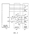
- FIG. 3 illustrates the use of a double-pole, double-throw (DPDT) switch 90 as a 2-to-3 Type Adapter for connecting a 2-lead monitor 41 to a 3-lead probe 10.
- Input signal VN1 is applied to a first input lead 42 of DPDT switch 90 and input signal VN2 is applied to a second input lead 43 of DPDT switch 90.
- the operation of this DPDT switch is most easily understood by viewing this switch as a pair of single-pole, double throw (SPDT) switches 44 and 45 having input leads 42, 43 and output leads 46-49.
- Output leads 46 and 49 are shorted together and are to be connected to the common anode terminal 410 of diodes 11 and 12.
- Output lead 47 is connected to the cathode 411 of LED 12 and output lead 48 is connected to the cathode 412 of LED 11.
- a control signal C controls the states of the SPDT switches such that the switches are either in: a first state in which only LED 11 is activated or in a second state in which only LED 12 is activated. This first state is illustrated by the solid line positions of SPDT switches 44 and 45 and the second state is illustrated by the dashed line positions of SPDT switches 44 and 45. In an alternate embodiment, the control signal C could be from lead 43.
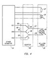
- Figure 4 illustrates an embodiment of a 3-to-2-type adapter that utilizes a double-pole, double-throw (DPDT) switch to enable input signals VO1 and VO2 to drive a 2-lead probe 20.
- DPDT double-pole, double-throw
- a double-pole, double-throw switch 92 functions as a 3-to-2-type adapter to connect a 3-lead monitor 51 to a 2-lead probe 20.
- Input signal VO1 is applied to a first input lead 52 of DPDT switch 92
- input signal VO2 is applied to a second input lead 53 of DPDT switch 92
- a ground GND of the monitor is connected to a third (common) input lead 54 of DPDT switch 92.
- a control signal D (which in this embodiment is derived from VO1) controls the state of the DPDT switch.
- the operation of this DPDT switch can be understood in terms of its equivalence to a pair of single-pole, double-throw switches 55 and 56.
- a first state illustrated by the solid line positions of SPDT switches 55 and 56
- VO1 is applied to a first output lead 57 that is connected to a first input lead 58 of probe 20 and ground GND is connected to a second output lead 59 that is connected to a second input lead 510 of probe 20, thereby turning on only LED 22.
- a second state (illustrated by the dashed line positions of SPDT switches 55 and 56), which occurs when VO1 is off and VO2 is negative, VO2 is applied to output lead 59 and ground GND is connected to output lead 57, thereby turning on only LED 21.
- the resulting signal pattern produced across LED 21 is therefore substantially identical to VN1 and the resulting signal pattern produced across LED 22 is therefore substantially identical to VN2.
- Adapters 40, 50 can be packaged into an oximeter system in a number of different ways. Either of these adapters can be: included within the monitor; mounted on a front panel of the monitor such that it can be connected to the appropriate leads from the monitor; included in the cable that connects the probe to the monitor (in a housing spliced withing the length of the cable); mounted at an input end of the probe such that it can be connected to appropriate leads from the probe; mounted in the cable connector to the monitor or to the probe; or included within the probe. It is preferred to have the adapter detachably connected to the cable and/or the monitor so that a user can utilize such adapter with existing types of cables and monitors to enable each of the above-discussed types of probes to be utilized with the other type of monitor.
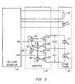
- FIG. 5 illustrates one preferred embodiment of a 2-to-3 Type Adapter 40, corresponding to the adapter presented in Figure 3.
- This adapter enables a a 2-lead monitor 41 to drive a 3-lead probe 10.
- This adapter contains a DPDT switch 90 consisting of LEDs 60-63 with corresponding phototransistors 60'-63'.
- the optical coupling does not require external power separate from the current provided by the monitor for the LEDs for this DPDT switch to operate. It is important to keep the current to the optical switches low by using resistors R because the adapter drains some of the current provided by the input signals VN1 and VN2, thereby reducing the amount of current applied to the probe LEDs 11 and 12.
- LEDs 62 and 63 When VN1 is high and VN2 is low (the first state of DPDT switch 90), LEDs 62 and 63 emit light to photodiodes 62' and'63', respectively, thereby connecting signal VN2 through photodiode 63', LED 12 and photodiode 62' to VN1. This turns LED 12 on. However, because LEDs 60 and 61 are reverse biased, the associated photodiodes 60' and 61' are in an off state so that LED 11 is off.
- LEDs 60 and 61 When VN1 is low and VN2 is high (the second state of DPDT switch 40), LEDs 60 and 61 emit light to photodiodes 60' and 61', respectively, thereby connecting signal VN1 through photodiode 61', LED 11 and photodiode 60' to VN2. This turns LED 11 on. However, because LEDs 62 and 63 are reverse biased, the associated photodiodes 62' and 63' are in an off state so that LED 12 is off.
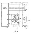
- Figure 6 illustrates a first preferred embodiment of a 3-to-2 Type Adapter that utilizes a set of four optically isolated switches with switching transistors 81-84 and control LEDs 81'-84'.
- the resistive current limiting on the switch inputs (LEDs 81'-84') again minimizes power consumption for active switching.
- These optically-coupled embodiments typically pass 80-90% of the power in the input signals to the output signals from the adapter.
- VO1 functions as an input signal that is selectively gated to the probe and also functions as a first control signal E.
- VO2 likewise functions as an input signal that is selectively gated to the probe and also functions as a second control signal E'.
- Switches 81 and 84 are conductive only when VO2 is negative and switches 82 and 83 are conductive only when VO1 is negative. When VO1 and VO2 are both at zero volts, all the switches 81-84 are nonconductive and neither of LEDs 21 and 22 is turned on. When VO1 is negative and VO2 is at zero volts, only switches 82 and 83 are turned on. This applies VO1, through switch 82 to lead 24 (making it negative), thereby turning LED 22 on through 83 to ground GND and turning LED 21 off. When VO1 is at zero volts and VO2 is negative, only switches 81 and 84 are turned on.
- VO1 and VO2 are never both low simultaneously, so there are only three distinct states: only LED 21 on; only LED 22 on; or both LED 21 and LED 22 off.
- FIG. 6 The embodiment of Figure 6 could be modified to eliminate transistors 82 and 84 (and the corresponding LEDs, 82', 84' providing direct connections instead.
- Transistors 82 and 84 serve to isolate VO1 or VO2 when it is not being used, and this is not necessary if the lines for VO1 and VO2 are at a high-impedance state when not being activated.
- An embodiment which would work with an output that is high impedance is shown in Figure 8, described below.
- Fig. 6 also shows an external coding element 86 which can be added in parallel (or alternately in series) with coding resistor 27 to modify its value to a value expected by a different type of monitor (element 86 can be a resistor or some other active or passive element). This is useful because different monitors use different resistor values for the same wavelength. This could be added to any of the probes or adapters shown, not just the embodiment of Fig. 6.
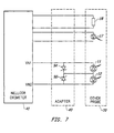
- FIG. 7 illustrates a second preferred embodiment of a 2-to-3 Type Adapter 40.
- This adapter uses two Schottky diodes 94 and 96.
- VN1 When VN1 is high, current will flow through Schottky diode 94 to the common node and through LED 12 back to the VN2 lead, which is low at this time. LED 11 will be reverse biased, and will not conduct, and neither will the Schottky diode 96.
- VN2 is high, current will flow through Schottky diode 96 and LED 11, returning to VN1, which is low at this time.
- LED 12 and Schottky diode 94 are reverse biased, with neither of them conducting.
- Schottky diodes are preferred over normal diodes since they have lower forward voltage drops.
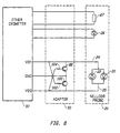
- FIG 8 illustrates a second preferred embodiment of a 3-to-2 Type Adapter 50.
- This adapter includes two transistors 98 and 100.
- the VO1 terminal is connected through a resistor 102 to the base of transistor 100.
- the VO2 signal is connected through a resistor 104 to the base of transistor 98.
- Both the transistors are PNP type transistors and thus will turn on when the base is low compared to their emitter.
- the emitters are connected to the ground terminal.
- VO1 or VO2 becomes negative with respect to ground.
- VO1 becomes negative, that turns on transistor 100, forming a path between ground and terminal 25 of the probe 20.
- current will flow from ground through transistor 100 through LED 22, which is turned on, and return to VO1.
- VO2 in a high impedance state, the base of transistor 98 will be negative by only the amount of the collector to emitter voltage drop of transistor 100, which will be insufficient to turn on transistor 98.
- transistor 100 when VO2 goes negative with respect to ground, transistor 100 will turn off (because VO1 is in a high impedance) and transistor 98 will turn on. Thus, current will flow from ground, through transistor 98, through LED 21 and return to VO2.
- the resistors are used to limit the amount of current drawn to activate transistors 98 and 100. This embodiment assumes VO1 and VO2 are in a high impedance state when inactive, and thus another set of switches for isolation is not needed.
- the present invention "steals" power (current) from the monitor's LED drive current in order to perform a function not performed within the pulse oximeter monitor.
- the function performed in a preferred embodiment is controlling the switching of connections. This is particularly true in the embodiments of Figures 5, 6 and 8, in which power is used to control the switches.
- the power not “stolen” is used to drive the probe LEDs.
- resistors can be used to limit the amount of current diverted.
- Figure 9 illustrates an embodiment of the present invention which may be incorporated into a cable for interconnecting a probe to an oximeter monitor.
- Figure 9 shows a cable 106 with a monitor connector 108 for connecting to a 3-lead monitor, and a probe connector 110 for connecting to a 3-lead probe.
- a connector 112 for connecting to a 2-lead monitor is provided, along with a connector 114 for connecting to a 2-lead probe.
- the use of such a universal cable would allow any type of monitor to be connected to any type of probe, eliminating the need to stock multiple types of adapters.
- Figure 10 shows the interconnections of the connector of Figure 9, with an adapter 50 interconnecting the 3-lead oximeter connector 108 to the 2-lead probe connector 114.
- adapter 40 interconnects the 2-lead oximeter monitor connector 112 to the 3-lead probe connector 110.
- This cable can be operated so that the connections not used are simply left open, providing an open circuit (high impedance) that would not affect the operation of the other adapter.
- a mode switch 116 could be added to actively disconnect the adapter which is not being used to prevent any possible power drain through its components while the other adapter is being used.
- the adapters 50, 40 and mode switch 116 would be preferably formed as a part of cable 106 or connected thereto.
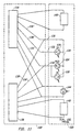
- Figure 11 is a diagram showing a dual use probe 120 and a corresponding adapter 122. Alternately, these could be combined in a single unit. In yet another alternative, the adapter could be eliminated and the probe 120 could be directly connected to either a two LED drive monitor or a 3 LED drive monitor.
- the dual use probe contains an 2-lead arrangement of LEDs 124 and 126. In this instance, LED 124 is preferably in the red wavelength band, and LED 126 is in the IR wavelength band. An additional LED 128 is added, corresponding to the second LED of the 3-lead arrangement.
- an output terminal 130 which is common to all the LEDs, a terminal 132 from the cathode of LED 128, and a terminal 134 from the cathode of LED 124, also connected to the anode of LED 126.
- the LEDs necessary for either type of probe, 10 or 20, are provided.
- Adapter 122 shows two different connectors, a connector 136 for a 3-lead monitor, and a connector 138 for a 2-lead monitor.
- a connector 136 for a 3-lead monitor For the 2-lead connector 138, only leads 130 and 134 of dual use probe 120 are used.
- 3-lead connector 136 all three leads 130, 132, and 134 are utilized.
- Lines 138' show how the 2 LED drive connector 138 is connected to alternately drive LEDs 124, 126, and lines 136' show how the 3 LED drive connector 136 is connected to alternately drive LEDs 126, 128.
- the drive interconnections can thus be made externally to the probe, thus making the probe equally applicable to either type of monitor.
- connector 138 when connector 138 is connected to a 2-lead monitor, only leads 130, 134 are utilized, with 132 being open. Since lead 132 is open, LED 128 is effectively taken out of the circuit, and the probe and monitor can operate in the normal manner using LEDs 124 and 126.
- LED 126 is effectively taken out of the circuit since current never flows in a direction which would activate it.
- lead 130 which is connected to ground, provides current to a negatively-biased lead 132 through IR LED 128.
- lead 134 is high impedance, and no current flows in this direction.
- lead 130 is again ground, with lead 132 being at a high impedance and lead 134 being pulled negative. This causes current to flow through red LED 124, but not through LED 126, which is reverse biased.
- IR LEDs Two different IR LEDs are used rather than two different red LEDs, since oximeter probes currently on the market will typically have red LEDs of approximately the same wavelength, while their IR LEDs differ.
- dual use probe 120 contains two coding elements (active or passive), 140 and 142.
- Coding element 140 is used to indicate the wavelength of red LED 124 (and/or other significant parameters) to a 3-lead type oximeter monitor connected to connector 136.
- a separate coding element 142 is used to indicate the wavelength of the red LED 124 (and/or other significant parameters) for a 2-lead monitor.
- the red LED will have the same wavelength, alternate coding schemes are used for monitors currently in the market for the same wavelengths. Accordingly, the leads of element 140 are only connected to connector 136, and the leads of element 142 are only connected to connector 138.
- the detector 144 is connected to both connectors.
- the invention has been described with reference to certain preferred embodiments thereof, it is not to be limited thereby. Any one of a variety of active switches are well known in the art and could readily be substituted for the double pole double throw switches described herein.
- numerous electronic elements other than the phototransistors and transistors described herein could be utilized to effectuate the electronic switching.
- a light emitter other than a LED could be used, with its terminals broadly referred to as an emitter drive terminal and an emitter output terminal, rather than an anode and cathode.
- the adapter could be designed to allow the 2-lead portion of the adapter to connect to either a 2-lead oximeter or a 2-lead probe, rather than being specialized to just one of these orientations.
- the 3-lead portion of the adapter could connect to either a 3-lead monitor or a 3-lead probe. All such equivalents are encompassed by the invention, the invention only being limited by the appended claims.
Landscapes
- Health & Medical Sciences (AREA)
- Physics & Mathematics (AREA)
- Life Sciences & Earth Sciences (AREA)
- Biomedical Technology (AREA)
- Medical Informatics (AREA)
- Biophysics (AREA)
- Pathology (AREA)
- Engineering & Computer Science (AREA)
- Spectroscopy & Molecular Physics (AREA)
- Heart & Thoracic Surgery (AREA)
- Optics & Photonics (AREA)
- Molecular Biology (AREA)
- Surgery (AREA)
- Animal Behavior & Ethology (AREA)
- General Health & Medical Sciences (AREA)
- Public Health (AREA)
- Veterinary Medicine (AREA)
- Measurement Of The Respiration, Hearing Ability, Form, And Blood Characteristics Of Living Organisms (AREA)
- Investigating Or Analysing Materials By Optical Means (AREA)
Applications Claiming Priority (3)
| Application Number | Priority Date | Filing Date | Title |
|---|---|---|---|
| US575336 | 1995-12-20 | ||
| US08/575,336 US5818985A (en) | 1995-12-20 | 1995-12-20 | Optical oximeter probe adapter |
| PCT/US1996/020551 WO1997022294A1 (en) | 1995-12-20 | 1996-12-18 | Optical oximeter probe adapter |
Publications (2)
| Publication Number | Publication Date |
|---|---|
| EP0957751A1 EP0957751A1 (en) | 1999-11-24 |
| EP0957751B1 true EP0957751B1 (en) | 2003-04-16 |
Family
ID=24299904
Family Applications (1)
| Application Number | Title | Priority Date | Filing Date |
|---|---|---|---|
| EP96945005A Expired - Lifetime EP0957751B1 (en) | 1995-12-20 | 1996-12-18 | Optical oximeter probe adapter |
Country Status (6)
| Country | Link |
|---|---|
| US (2) | US5818985A (enExample) |
| EP (1) | EP0957751B1 (enExample) |
| JP (1) | JP3825052B2 (enExample) |
| AU (1) | AU1347297A (enExample) |
| DE (1) | DE69627544T2 (enExample) |
| WO (1) | WO1997022294A1 (enExample) |
Families Citing this family (139)
| Publication number | Priority date | Publication date | Assignee | Title |
|---|---|---|---|---|
| US6541756B2 (en) * | 1991-03-21 | 2003-04-01 | Masimo Corporation | Shielded optical probe having an electrical connector |
| US5995855A (en) | 1998-02-11 | 1999-11-30 | Masimo Corporation | Pulse oximetry sensor adapter |
| US5818985A (en) * | 1995-12-20 | 1998-10-06 | Nellcor Puritan Bennett Incorporated | Optical oximeter probe adapter |
| US6018673A (en) | 1996-10-10 | 2000-01-25 | Nellcor Puritan Bennett Incorporated | Motion compatible sensor for non-invasive optical blood analysis |
| US6405145B1 (en) * | 1998-03-20 | 2002-06-11 | National Instruments Corporation | Instrumentation system and method which performs instrument interchangeability checking |
| EP1117327A1 (en) * | 1998-09-29 | 2001-07-25 | Mallinckrodt Inc. | Multiple-code oximeter calibration element |
| USRE38935E1 (en) | 1998-10-29 | 2006-01-10 | Advanced Medical Optics, Inc. | Intraocular lenses made from polymeric compositions and monomers useful in said compositions |
| US6245106B1 (en) | 1998-10-29 | 2001-06-12 | Allergan Sales, Inc. | Intraocular lenses made from polymeric compositions and monomers useful in said compositions |
| US8103325B2 (en) * | 1999-03-08 | 2012-01-24 | Tyco Healthcare Group Lp | Method and circuit for storing and providing historical physiological data |
| US6675031B1 (en) | 1999-04-14 | 2004-01-06 | Mallinckrodt Inc. | Method and circuit for indicating quality and accuracy of physiological measurements |
| US6665551B1 (en) | 1999-11-19 | 2003-12-16 | Nihon Kohden Corporation | Current driving system of light emitting diode |
| US6377829B1 (en) | 1999-12-09 | 2002-04-23 | Masimo Corporation | Resposable pulse oximetry sensor |
| US8224412B2 (en) | 2000-04-17 | 2012-07-17 | Nellcor Puritan Bennett Llc | Pulse oximeter sensor with piece-wise function |
| EP2684514B1 (en) | 2000-04-17 | 2018-10-24 | Covidien LP | Pulse oximeter sensor with piece-wise function |
| US6697656B1 (en) * | 2000-06-27 | 2004-02-24 | Masimo Corporation | Pulse oximetry sensor compatible with multiple pulse oximetry systems |
| US6606510B2 (en) | 2000-08-31 | 2003-08-12 | Mallinckrodt Inc. | Oximeter sensor with digital memory encoding patient data |
| US6591123B2 (en) * | 2000-08-31 | 2003-07-08 | Mallinckrodt Inc. | Oximeter sensor with digital memory recording sensor data |
| US6490466B1 (en) * | 2000-09-21 | 2002-12-03 | Mallinckrodt Inc. | Interconnect circuit between non-compatible oximeter and sensor |
| US6571113B1 (en) | 2000-09-21 | 2003-05-27 | Mallinckrodt, Inc. | Oximeter sensor adapter with coding element |
| US6668183B2 (en) | 2001-09-11 | 2003-12-23 | Datex-Ohmeda, Inc. | Diode detection circuit |
| US6697653B2 (en) | 2001-10-10 | 2004-02-24 | Datex-Ohmeda, Inc. | Reduced wire count voltage drop sense |
| US6748254B2 (en) | 2001-10-12 | 2004-06-08 | Nellcor Puritan Bennett Incorporated | Stacked adhesive optical sensor |
| AU2003205392A1 (en) * | 2002-01-31 | 2003-09-02 | Datex-Ohmeda, Inc. | Sensor identification method and system |
| US7509494B2 (en) * | 2002-03-01 | 2009-03-24 | Masimo Corporation | Interface cable |
| US7190986B1 (en) | 2002-10-18 | 2007-03-13 | Nellcor Puritan Bennett Inc. | Non-adhesive oximeter sensor for sensitive skin |
| US7027849B2 (en) * | 2002-11-22 | 2006-04-11 | Masimo Laboratories, Inc. | Blood parameter measurement system |
| US7305262B2 (en) * | 2003-12-11 | 2007-12-04 | Ge Medical Systems Information Technologies, Inc. | Apparatus and method for acquiring oximetry and electrocardiogram signals |
| US7162288B2 (en) | 2004-02-25 | 2007-01-09 | Nellcor Purtain Bennett Incorporated | Techniques for detecting heart pulses and reducing power consumption in sensors |
| US7373192B2 (en) * | 2004-02-25 | 2008-05-13 | Nellcor Puritan Bennett Inc. | Oximeter red and IR zero calibration control |
| US7957780B2 (en) | 2005-03-01 | 2011-06-07 | Masimo Laboratories, Inc. | Physiological parameter confidence measure |
| US7590439B2 (en) | 2005-08-08 | 2009-09-15 | Nellcor Puritan Bennett Llc | Bi-stable medical sensor and technique for using the same |
| US7657294B2 (en) | 2005-08-08 | 2010-02-02 | Nellcor Puritan Bennett Llc | Compliant diaphragm medical sensor and technique for using the same |
| US7657295B2 (en) | 2005-08-08 | 2010-02-02 | Nellcor Puritan Bennett Llc | Medical sensor and technique for using the same |
| US20070060808A1 (en) | 2005-09-12 | 2007-03-15 | Carine Hoarau | Medical sensor for reducing motion artifacts and technique for using the same |
| US8092379B2 (en) | 2005-09-29 | 2012-01-10 | Nellcor Puritan Bennett Llc | Method and system for determining when to reposition a physiological sensor |
| US7869850B2 (en) | 2005-09-29 | 2011-01-11 | Nellcor Puritan Bennett Llc | Medical sensor for reducing motion artifacts and technique for using the same |
| US7899510B2 (en) | 2005-09-29 | 2011-03-01 | Nellcor Puritan Bennett Llc | Medical sensor and technique for using the same |
| US7904130B2 (en) | 2005-09-29 | 2011-03-08 | Nellcor Puritan Bennett Llc | Medical sensor and technique for using the same |
| US7486979B2 (en) | 2005-09-30 | 2009-02-03 | Nellcor Puritan Bennett Llc | Optically aligned pulse oximetry sensor and technique for using the same |
| US7881762B2 (en) | 2005-09-30 | 2011-02-01 | Nellcor Puritan Bennett Llc | Clip-style medical sensor and technique for using the same |
| US8233954B2 (en) | 2005-09-30 | 2012-07-31 | Nellcor Puritan Bennett Llc | Mucosal sensor for the assessment of tissue and blood constituents and technique for using the same |
| US7483731B2 (en) | 2005-09-30 | 2009-01-27 | Nellcor Puritan Bennett Llc | Medical sensor and technique for using the same |
| US7555327B2 (en) | 2005-09-30 | 2009-06-30 | Nellcor Puritan Bennett Llc | Folding medical sensor and technique for using the same |
| US8062221B2 (en) | 2005-09-30 | 2011-11-22 | Nellcor Puritan Bennett Llc | Sensor for tissue gas detection and technique for using the same |
| US20070093717A1 (en) * | 2005-10-20 | 2007-04-26 | Glucon Inc. | Wearable glucometer configurations |
| US20070149864A1 (en) * | 2005-12-27 | 2007-06-28 | Marko Laakkonen | Monitoring device for multiple tissue sites |
| US7606606B2 (en) * | 2005-12-27 | 2009-10-20 | General Electric Company | Patient monitoring device with multiple sensors |
| US8073518B2 (en) | 2006-05-02 | 2011-12-06 | Nellcor Puritan Bennett Llc | Clip-style medical sensor and technique for using the same |
| US7522948B2 (en) | 2006-05-02 | 2009-04-21 | Nellcor Puritan Bennett Llc | Medical sensor and technique for using the same |
| US7477924B2 (en) | 2006-05-02 | 2009-01-13 | Nellcor Puritan Bennett Llc | Medical sensor and technique for using the same |
| US10188348B2 (en) | 2006-06-05 | 2019-01-29 | Masimo Corporation | Parameter upgrade system |
| US8145288B2 (en) | 2006-08-22 | 2012-03-27 | Nellcor Puritan Bennett Llc | Medical sensor for reducing signal artifacts and technique for using the same |
| US20080064940A1 (en) * | 2006-09-12 | 2008-03-13 | Raridan William B | Sensor cable design for use with spectrophotometric sensors and method of using the same |
| US8219170B2 (en) | 2006-09-20 | 2012-07-10 | Nellcor Puritan Bennett Llc | System and method for practicing spectrophotometry using light emitting nanostructure devices |
| US8195264B2 (en) | 2006-09-22 | 2012-06-05 | Nellcor Puritan Bennett Llc | Medical sensor for reducing signal artifacts and technique for using the same |
| US8175671B2 (en) | 2006-09-22 | 2012-05-08 | Nellcor Puritan Bennett Llc | Medical sensor for reducing signal artifacts and technique for using the same |
| US8396527B2 (en) | 2006-09-22 | 2013-03-12 | Covidien Lp | Medical sensor for reducing signal artifacts and technique for using the same |
| US7869849B2 (en) | 2006-09-26 | 2011-01-11 | Nellcor Puritan Bennett Llc | Opaque, electrically nonconductive region on a medical sensor |
| US7574245B2 (en) | 2006-09-27 | 2009-08-11 | Nellcor Puritan Bennett Llc | Flexible medical sensor enclosure |
| US20080082024A1 (en) * | 2006-09-28 | 2008-04-03 | Meyer Peter F | Signal replication medical apparatus |
| US7796403B2 (en) | 2006-09-28 | 2010-09-14 | Nellcor Puritan Bennett Llc | Means for mechanical registration and mechanical-electrical coupling of a faraday shield to a photodetector and an electrical circuit |
| US7890153B2 (en) | 2006-09-28 | 2011-02-15 | Nellcor Puritan Bennett Llc | System and method for mitigating interference in pulse oximetry |
| US8175667B2 (en) | 2006-09-29 | 2012-05-08 | Nellcor Puritan Bennett Llc | Symmetric LED array for pulse oximetry |
| US8068891B2 (en) | 2006-09-29 | 2011-11-29 | Nellcor Puritan Bennett Llc | Symmetric LED array for pulse oximetry |
| US7680522B2 (en) | 2006-09-29 | 2010-03-16 | Nellcor Puritan Bennett Llc | Method and apparatus for detecting misapplied sensors |
| US7684842B2 (en) | 2006-09-29 | 2010-03-23 | Nellcor Puritan Bennett Llc | System and method for preventing sensor misuse |
| US7476131B2 (en) | 2006-09-29 | 2009-01-13 | Nellcor Puritan Bennett Llc | Device for reducing crosstalk |
| US7880626B2 (en) | 2006-10-12 | 2011-02-01 | Masimo Corporation | System and method for monitoring the life of a physiological sensor |
| US8265723B1 (en) | 2006-10-12 | 2012-09-11 | Cercacor Laboratories, Inc. | Oximeter probe off indicator defining probe off space |
| US8652040B2 (en) | 2006-12-19 | 2014-02-18 | Valencell, Inc. | Telemetric apparatus for health and environmental monitoring |
| US8157730B2 (en) | 2006-12-19 | 2012-04-17 | Valencell, Inc. | Physiological and environmental monitoring systems and methods |
| WO2008085411A2 (en) * | 2006-12-27 | 2008-07-17 | Valencell, Inc. | Multi-wavelength optical devices and methods of using same |
| US8280469B2 (en) | 2007-03-09 | 2012-10-02 | Nellcor Puritan Bennett Llc | Method for detection of aberrant tissue spectra |
| US7894869B2 (en) | 2007-03-09 | 2011-02-22 | Nellcor Puritan Bennett Llc | Multiple configuration medical sensor and technique for using the same |
| US8265724B2 (en) | 2007-03-09 | 2012-09-11 | Nellcor Puritan Bennett Llc | Cancellation of light shunting |
| US8781544B2 (en) | 2007-03-27 | 2014-07-15 | Cercacor Laboratories, Inc. | Multiple wavelength optical sensor |
| US8374665B2 (en) | 2007-04-21 | 2013-02-12 | Cercacor Laboratories, Inc. | Tissue profile wellness monitor |
| US8251903B2 (en) | 2007-10-25 | 2012-08-28 | Valencell, Inc. | Noninvasive physiological analysis using excitation-sensor modules and related devices and methods |
| US8346328B2 (en) | 2007-12-21 | 2013-01-01 | Covidien Lp | Medical sensor and technique for using the same |
| US8352004B2 (en) | 2007-12-21 | 2013-01-08 | Covidien Lp | Medical sensor and technique for using the same |
| US8366613B2 (en) | 2007-12-26 | 2013-02-05 | Covidien Lp | LED drive circuit for pulse oximetry and method for using same |
| US8577434B2 (en) | 2007-12-27 | 2013-11-05 | Covidien Lp | Coaxial LED light sources |
| US20090168050A1 (en) * | 2007-12-27 | 2009-07-02 | Nellcor Puritan Bennett Llc | Optical Sensor System And Method |
| US8442608B2 (en) | 2007-12-28 | 2013-05-14 | Covidien Lp | System and method for estimating physiological parameters by deconvolving artifacts |
| US8452364B2 (en) | 2007-12-28 | 2013-05-28 | Covidien LLP | System and method for attaching a sensor to a patient's skin |
| US20090171171A1 (en) * | 2007-12-31 | 2009-07-02 | Nellcor Puritan Bennett Llc | Oximetry sensor overmolding location features |
| US8199007B2 (en) | 2007-12-31 | 2012-06-12 | Nellcor Puritan Bennett Llc | Flex circuit snap track for a biometric sensor |
| US8897850B2 (en) | 2007-12-31 | 2014-11-25 | Covidien Lp | Sensor with integrated living hinge and spring |
| US8070508B2 (en) | 2007-12-31 | 2011-12-06 | Nellcor Puritan Bennett Llc | Method and apparatus for aligning and securing a cable strain relief |
| US20090171166A1 (en) * | 2007-12-31 | 2009-07-02 | Nellcor Puritan Bennett Llc | Oximeter with location awareness |
| US8092993B2 (en) | 2007-12-31 | 2012-01-10 | Nellcor Puritan Bennett Llc | Hydrogel thin film for use as a biosensor |
| US20090247854A1 (en) * | 2008-03-27 | 2009-10-01 | Nellcor Puritan Bennett Llc | Retractable Sensor Cable For A Pulse Oximeter |
| US8437822B2 (en) | 2008-03-28 | 2013-05-07 | Covidien Lp | System and method for estimating blood analyte concentration |
| US8364224B2 (en) | 2008-03-31 | 2013-01-29 | Covidien Lp | System and method for facilitating sensor and monitor communication |
| US8112375B2 (en) | 2008-03-31 | 2012-02-07 | Nellcor Puritan Bennett Llc | Wavelength selection and outlier detection in reduced rank linear models |
| JP2011519684A (ja) | 2008-05-05 | 2011-07-14 | マシモ コーポレイション | 電気切り離し回路を備えるパルス酸素濃度計システム |
| US8071935B2 (en) | 2008-06-30 | 2011-12-06 | Nellcor Puritan Bennett Llc | Optical detector with an overmolded faraday shield |
| US7887345B2 (en) | 2008-06-30 | 2011-02-15 | Nellcor Puritan Bennett Llc | Single use connector for pulse oximetry sensors |
| US7880884B2 (en) | 2008-06-30 | 2011-02-01 | Nellcor Puritan Bennett Llc | System and method for coating and shielding electronic sensor components |
| US8364220B2 (en) | 2008-09-25 | 2013-01-29 | Covidien Lp | Medical sensor and technique for using the same |
| US20100076276A1 (en) * | 2008-09-25 | 2010-03-25 | Nellcor Puritan Bennett Llc | Medical Sensor, Display, and Technique For Using The Same |
| US8423112B2 (en) | 2008-09-30 | 2013-04-16 | Covidien Lp | Medical sensor and technique for using the same |
| US8417309B2 (en) | 2008-09-30 | 2013-04-09 | Covidien Lp | Medical sensor |
| US8914088B2 (en) | 2008-09-30 | 2014-12-16 | Covidien Lp | Medical sensor and technique for using the same |
| US9750462B2 (en) | 2009-02-25 | 2017-09-05 | Valencell, Inc. | Monitoring apparatus and methods for measuring physiological and/or environmental conditions |
| US8788002B2 (en) | 2009-02-25 | 2014-07-22 | Valencell, Inc. | Light-guiding devices and monitoring devices incorporating same |
| JP5789199B2 (ja) | 2009-02-25 | 2015-10-07 | ヴァレンセル,インコーポレイテッド | ヘッドセット及びイアバッド |
| US8452366B2 (en) | 2009-03-16 | 2013-05-28 | Covidien Lp | Medical monitoring device with flexible circuitry |
| US20100249550A1 (en) * | 2009-03-25 | 2010-09-30 | Neilcor Puritan Bennett LLC | Method And Apparatus For Optical Filtering Of A Broadband Emitter In A Medical Sensor |
| US8221319B2 (en) | 2009-03-25 | 2012-07-17 | Nellcor Puritan Bennett Llc | Medical device for assessing intravascular blood volume and technique for using the same |
| US8509869B2 (en) | 2009-05-15 | 2013-08-13 | Covidien Lp | Method and apparatus for detecting and analyzing variations in a physiologic parameter |
| US8634891B2 (en) | 2009-05-20 | 2014-01-21 | Covidien Lp | Method and system for self regulation of sensor component contact pressure |
| US8571619B2 (en) | 2009-05-20 | 2013-10-29 | Masimo Corporation | Hemoglobin display and patient treatment |
| US8188433B2 (en) * | 2009-05-26 | 2012-05-29 | Nellcor Puritan Bennett Llc | Physiological sensor having reduced sensitivity to interference |
| US8505821B2 (en) | 2009-06-30 | 2013-08-13 | Covidien Lp | System and method for providing sensor quality assurance |
| US8311601B2 (en) | 2009-06-30 | 2012-11-13 | Nellcor Puritan Bennett Llc | Reflectance and/or transmissive pulse oximeter |
| US9010634B2 (en) | 2009-06-30 | 2015-04-21 | Covidien Lp | System and method for linking patient data to a patient and providing sensor quality assurance |
| US20100331631A1 (en) * | 2009-06-30 | 2010-12-30 | Nellcor Puritan Bennett Llc | Oxygen saturation ear sensor design that optimizes both attachment method and signal quality |
| US8391941B2 (en) | 2009-07-17 | 2013-03-05 | Covidien Lp | System and method for memory switching for multiple configuration medical sensor |
| US8417310B2 (en) | 2009-08-10 | 2013-04-09 | Covidien Lp | Digital switching in multi-site sensor |
| US8428675B2 (en) | 2009-08-19 | 2013-04-23 | Covidien Lp | Nanofiber adhesives used in medical devices |
| US9106038B2 (en) | 2009-10-15 | 2015-08-11 | Masimo Corporation | Pulse oximetry system with low noise cable hub |
| US9839381B1 (en) | 2009-11-24 | 2017-12-12 | Cercacor Laboratories, Inc. | Physiological measurement system with automatic wavelength adjustment |
| DE112010004682T5 (de) | 2009-12-04 | 2013-03-28 | Masimo Corporation | Kalibrierung für mehrstufige physiologische Monitore |
| JP5570802B2 (ja) * | 2009-12-24 | 2014-08-13 | オリンパス株式会社 | 内視鏡装置 |
| CN103327894B (zh) * | 2011-01-19 | 2016-05-04 | 加利福尼亚大学董事会 | 组织的血氧定量测定和灌注成像的设备、系统及方法 |
| US8888701B2 (en) | 2011-01-27 | 2014-11-18 | Valencell, Inc. | Apparatus and methods for monitoring physiological data during environmental interference |
| US9427191B2 (en) | 2011-07-25 | 2016-08-30 | Valencell, Inc. | Apparatus and methods for estimating time-state physiological parameters |
| EP3222210B1 (en) | 2011-08-02 | 2024-09-25 | Yukka Magic LLC | Systems and methods for variable filter adjustment by heart rate metric feedback |
| US10076253B2 (en) | 2013-01-28 | 2018-09-18 | Valencell, Inc. | Physiological monitoring devices having sensing elements decoupled from body motion |
| US20160029898A1 (en) | 2014-07-30 | 2016-02-04 | Valencell, Inc. | Physiological Monitoring Devices and Methods Using Optical Sensors |
| EP4098178B1 (en) | 2014-08-06 | 2024-04-10 | Yukka Magic LLC | Optical physiological sensor modules with reduced signal noise |
| US9794653B2 (en) | 2014-09-27 | 2017-10-17 | Valencell, Inc. | Methods and apparatus for improving signal quality in wearable biometric monitoring devices |
| JPWO2017018114A1 (ja) * | 2015-07-30 | 2018-05-31 | アルプス電気株式会社 | センサモジュールおよび生体関連情報表示システム |
| US10945618B2 (en) | 2015-10-23 | 2021-03-16 | Valencell, Inc. | Physiological monitoring devices and methods for noise reduction in physiological signals based on subject activity type |
| HK1249839A1 (zh) | 2015-10-23 | 2018-11-16 | Valencell, Inc. | 辨认研究对象活动类型的生理监测装置和方法 |
| US10966662B2 (en) | 2016-07-08 | 2021-04-06 | Valencell, Inc. | Motion-dependent averaging for physiological metric estimating systems and methods |
| CN108283498B (zh) * | 2018-03-21 | 2024-11-12 | 深圳市索莱瑞医疗技术有限公司 | 多兼容脉搏血氧传感器、适配电缆、适配器及组合 |
| EP4487763A3 (en) | 2018-07-16 | 2025-01-22 | BBI Medical Innovations, LLC | Perfusion and oxygenation measurement |
Family Cites Families (8)
| Publication number | Priority date | Publication date | Assignee | Title |
|---|---|---|---|---|
| US4278327A (en) * | 1979-11-26 | 1981-07-14 | Sperry Corporation | Liquid crystal matrices |
| US4453218A (en) * | 1980-11-24 | 1984-06-05 | Oximetrix, Inc. | Signal filter method and apparatus |
| US5249576A (en) * | 1991-10-24 | 1993-10-05 | Boc Health Care, Inc. | Universal pulse oximeter probe |
| US5287853A (en) * | 1992-12-11 | 1994-02-22 | Hewlett-Packard Company | Adapter cable for connecting a pulsoximetry sensor unit to a medical measuring device |
| US5743261A (en) * | 1993-12-06 | 1998-04-28 | Sensor Devices, Inc. | Methods and apparatus for the invasive use of oximeter probes |
| US5715816A (en) * | 1993-12-06 | 1998-02-10 | Sensor Devices, Inc. | Oximeter probes and methods for the invasive use thereof |
| US5417207A (en) * | 1993-12-06 | 1995-05-23 | Sensor Devices, Inc. | Apparatus for the invasive use of oximeter probes |
| US5818985A (en) * | 1995-12-20 | 1998-10-06 | Nellcor Puritan Bennett Incorporated | Optical oximeter probe adapter |
-
1995
- 1995-12-20 US US08/575,336 patent/US5818985A/en not_active Expired - Lifetime
-
1996
- 1996-12-18 JP JP52304397A patent/JP3825052B2/ja not_active Expired - Fee Related
- 1996-12-18 EP EP96945005A patent/EP0957751B1/en not_active Expired - Lifetime
- 1996-12-18 AU AU13472/97A patent/AU1347297A/en not_active Abandoned
- 1996-12-18 DE DE69627544T patent/DE69627544T2/de not_active Expired - Lifetime
- 1996-12-18 WO PCT/US1996/020551 patent/WO1997022294A1/en not_active Ceased
-
1998
- 1998-03-17 US US09/040,218 patent/US6023541A/en not_active Expired - Lifetime
Also Published As
| Publication number | Publication date |
|---|---|
| HK1026128A1 (en) | 2000-12-08 |
| DE69627544D1 (de) | 2003-05-22 |
| AU1347297A (en) | 1997-07-14 |
| EP0957751A1 (en) | 1999-11-24 |
| US6023541A (en) | 2000-02-08 |
| JP3825052B2 (ja) | 2006-09-20 |
| US5818985A (en) | 1998-10-06 |
| WO1997022294A1 (en) | 1997-06-26 |
| DE69627544T2 (de) | 2004-04-08 |
| JP2000501974A (ja) | 2000-02-22 |
Similar Documents
| Publication | Publication Date | Title |
|---|---|---|
| EP0957751B1 (en) | Optical oximeter probe adapter | |
| US7844313B2 (en) | Pulse oximetry sensor adapter | |
| US7027849B2 (en) | Blood parameter measurement system | |
| US6571113B1 (en) | Oximeter sensor adapter with coding element | |
| US6490466B1 (en) | Interconnect circuit between non-compatible oximeter and sensor | |
| US6697656B1 (en) | Pulse oximetry sensor compatible with multiple pulse oximetry systems | |
| US5827182A (en) | Multiple LED sets in oximetry sensors | |
| US6298252B1 (en) | Oximeter sensor with encoder connected to detector | |
| US20140296664A1 (en) | Emitter driver for noninvasive patient monitor | |
| US20130324808A1 (en) | Duo connector patient cable | |
| US20070149864A1 (en) | Monitoring device for multiple tissue sites | |
| US7841985B2 (en) | Sensor identification method and system | |
| US7650175B2 (en) | Method and device for detecting fault in a blood oxygen sensor | |
| CA2239080C (en) | Optical oximeter probe adapter | |
| HK1026128B (en) | Optical oximeter probe adapter | |
| EP3769678A1 (en) | Multi-compatibility pulse blood oxygen sensor, adaptive cable, adapter and combination thereof | |
| US20240023843A1 (en) | Vital-sign sensors |
Legal Events
| Date | Code | Title | Description |
|---|---|---|---|
| PUAI | Public reference made under article 153(3) epc to a published international application that has entered the european phase |
Free format text: ORIGINAL CODE: 0009012 |
|
| 17P | Request for examination filed |
Effective date: 19980720 |
|
| AK | Designated contracting states |
Kind code of ref document: A1 Designated state(s): DE FR GB |
|
| GRAH | Despatch of communication of intention to grant a patent |
Free format text: ORIGINAL CODE: EPIDOS IGRA |
|
| GRAH | Despatch of communication of intention to grant a patent |
Free format text: ORIGINAL CODE: EPIDOS IGRA |
|
| GRAA | (expected) grant |
Free format text: ORIGINAL CODE: 0009210 |
|
| AK | Designated contracting states |
Designated state(s): DE FR GB |
|
| REG | Reference to a national code |
Ref country code: GB Ref legal event code: FG4D |
|
| REF | Corresponds to: |
Ref document number: 69627544 Country of ref document: DE Date of ref document: 20030522 Kind code of ref document: P |
|
| ET | Fr: translation filed | ||
| PLBE | No opposition filed within time limit |
Free format text: ORIGINAL CODE: 0009261 |
|
| STAA | Information on the status of an ep patent application or granted ep patent |
Free format text: STATUS: NO OPPOSITION FILED WITHIN TIME LIMIT |
|
| 26N | No opposition filed |
Effective date: 20040119 |
|
| PGFP | Annual fee paid to national office [announced via postgrant information from national office to epo] |
Ref country code: GB Payment date: 20091229 Year of fee payment: 14 Ref country code: FR Payment date: 20100106 Year of fee payment: 14 |
|
| PGFP | Annual fee paid to national office [announced via postgrant information from national office to epo] |
Ref country code: DE Payment date: 20091230 Year of fee payment: 14 |
|
| GBPC | Gb: european patent ceased through non-payment of renewal fee |
Effective date: 20101218 |
|
| REG | Reference to a national code |
Ref country code: FR Ref legal event code: ST Effective date: 20110831 |
|
| PG25 | Lapsed in a contracting state [announced via postgrant information from national office to epo] |
Ref country code: FR Free format text: LAPSE BECAUSE OF NON-PAYMENT OF DUE FEES Effective date: 20110103 |
|
| REG | Reference to a national code |
Ref country code: DE Ref legal event code: R119 Ref document number: 69627544 Country of ref document: DE Effective date: 20110701 |
|
| PG25 | Lapsed in a contracting state [announced via postgrant information from national office to epo] |
Ref country code: GB Free format text: LAPSE BECAUSE OF NON-PAYMENT OF DUE FEES Effective date: 20101218 Ref country code: DE Free format text: LAPSE BECAUSE OF NON-PAYMENT OF DUE FEES Effective date: 20110701 |