EP0957562A2 - Stepping motor - Google Patents
Stepping motor Download PDFInfo
- Publication number
- EP0957562A2 EP0957562A2 EP99103399A EP99103399A EP0957562A2 EP 0957562 A2 EP0957562 A2 EP 0957562A2 EP 99103399 A EP99103399 A EP 99103399A EP 99103399 A EP99103399 A EP 99103399A EP 0957562 A2 EP0957562 A2 EP 0957562A2
- Authority
- EP
- European Patent Office
- Prior art keywords
- bush
- casings
- stator core
- stepping motor
- supported
- Prior art date
- Legal status (The legal status is an assumption and is not a legal conclusion. Google has not performed a legal analysis and makes no representation as to the accuracy of the status listed.)
- Granted
Links
Images


Classifications
-
- H—ELECTRICITY
- H02—GENERATION; CONVERSION OR DISTRIBUTION OF ELECTRIC POWER
- H02K—DYNAMO-ELECTRIC MACHINES
- H02K5/00—Casings; Enclosures; Supports
- H02K5/04—Casings or enclosures characterised by the shape, form or construction thereof
- H02K5/16—Means for supporting bearings, e.g. insulating supports or means for fitting bearings in the bearing-shields
- H02K5/161—Means for supporting bearings, e.g. insulating supports or means for fitting bearings in the bearing-shields radially supporting the rotary shaft at both ends of the rotor
-
- H—ELECTRICITY
- H02—GENERATION; CONVERSION OR DISTRIBUTION OF ELECTRIC POWER
- H02K—DYNAMO-ELECTRIC MACHINES
- H02K5/00—Casings; Enclosures; Supports
- H02K5/04—Casings or enclosures characterised by the shape, form or construction thereof
- H02K5/15—Mounting arrangements for bearing-shields or end plates
-
- H—ELECTRICITY
- H02—GENERATION; CONVERSION OR DISTRIBUTION OF ELECTRIC POWER
- H02K—DYNAMO-ELECTRIC MACHINES
- H02K5/00—Casings; Enclosures; Supports
- H02K5/24—Casings; Enclosures; Supports specially adapted for suppression or reduction of noise or vibrations
Definitions
- the present invention relates to a stepping motor used in an OA machine for processing image information such as a facsimile, an ink jet printer, a laser beam printer, a copying machine or the like.
- a rotor 5 composed of a pair of disc-like rotor cores 2 and 3 and a magnet 4 interposed therebetween is mounted on a rotary shaft 1.
- the rotary shaft 1 is supported by bearings 8 and 9 which are fixed by projected portions 6a and 7a of aluminum-made front casing 6 and rear casing 7, respectively.
- Stepped portions 6b and 7b are formed at confronting portions of the front and rear casings 6 and 7.
- An outer circumferential portion of a stator core 10 is supported by the stepped portions 6b and 7b.
- a stator coil 11 is wound around the stator core 10 and is connected to a drive circuit (not shown).
- this stepping motor current is intermittently supplied from the drive circuit (not shown) to the stator core 11 to thereby intermittently rotate the rotor 5.
- the rotational property of this arrangement depends upon uniformity of a fine gap formed between an inner diameter of the stator core 10 and an outer diameter of the rotor 5.
- an eccentric amount of the outer fitting portions of the casings 6 and 7 in the assembled condition of the stator core 10 to the casings 6 and 7 is added to an eccentric amount of the inner diameter of the stator core 10 before the assembling work.
- the fine gap between the inner diameter of the stator core 10 and the outer diameter of the rotor 5 becomes an eccentric gap, sometimes resulting in non-uniformity.
- the arrangement suffers from a problem that the dimensional precision of the outer diameter to the inner diameter of the stator core 10 and the dimensional precision of the outer circumferential fitting portions of the casings to the dimension of the fitting portions of the bearings 8 and 9 must be high in machining.
- the arrangement is modified in design in a stepping motor as shown in Fig. 14.
- the stepped portions 6c and 7c are formed on the outer circumferential side of the projected portions 6a and 7a of the front and rear casings 6 and 7.
- the inner circumferential portion of the stator core 10 is received by the stepped portions 6c and 7c. If such an arrangement is adopted, the inner circumferential portion of the stator core 10 is directly supported. It is therefore possible to remove the eccentric factor to be generated between the inner diameter of the stator core 10 and the outer diameter of the rotor 5. Thus, it is possible to solve the above-noted problem.
- Fig. 15 shows a design for the purpose of reducing the manufacture cost.
- the shape of the design is simplified in which, after the front casing 6 has been cast in aluminum, the front casing 6 is machined.
- the front casing 6 is shaped by metal-plate pressing.
- the eccentric factor to be generated between the inner diameter of the stator core 10 and the outer diameter of the rotor 5 is the same as that shown in Fig. 13.
- the structure shown in Fig. 15 exemplifies the structure in which the plate 12 is arranged in front of the front casing 6, the plate 12 may not be used.
- Fig. 16 shows a design for the purpose of enhancing the rotational gap precision of the design shown in Fig. 15. Bearing fitting portions of the metal plates are extended and the stepped portions 6c and 7c are formed in the extended portions. The inner circumferential portion of the stator core 10 is received by the stepped portions 6c and 7c.
- this structure suffers from a defect that, as shown by the arrows in Fig. 16, the magnetic field generated in the stator core 10 leaks to the casings 6 and 7 of the metal plates to considerably deteriorate the motor performance. Accordingly, in order to obviate the magnetic leakage in the structure in which the casings 6 and 7 are formed by pressing the metal plate, it is necessary to magnetically shield the inner diameter fitting portions of the stator core 10. It is impossible to take a structure in which the stator core 10 is held in the inner diameter portion.
- an object of the present invention is to provide a structure in which the above-noted defects do not occur even in the case where the casings are made by pressing metal plate.
- the stepping motor in a stepping motor having a structure in which a stator core is disposed outside of a rotor mounted on a rotary shaft, and a rear portion and a front portion of the rotary shaft are supported by bearings mounted on casings provided on the front and rear sides of the stator core, respectively, the stepping motor is characterized in that the casings are press-formed with a metal plate, a bush made of non-magnetic material is mounted on at least one of the casings, and the stator core is supported by the bush.
- the bush supports at least one of the bearings.
- the bush is made of non-magnetic metallic material, and fixed to at least one of the casings by either adhesives or press-fitting.
- a plurality of projected pieces directed inwardly for receiving an outer circumference of at least one of the bearings is formed integrally with a portion of at least one of the casings onto which at least one of the bearing is mounted, synthetic resin is filled in between the projected pieces and the stator core circumferentially so that the bush is mounted.
- the bush which is made of thermoplastic resin is fixed to at least one of the casings.
- the stepping motor in which a stator core is disposed outside of a rotor mounted on a rotary shaft, and a rear portion and a front portion of the rotary shaft are supported to bearings mounted on casings provided on the front and rear sides of the stator core, respectively, the stepping motor is characterized in that a bush made of non-magnetic material is mounted on one of the stator cores, and at least one of the casings is mounted on the bush.
- the bush supports at least one of the bearings.
- the bush is made of non-magnetic metallic material, and fixed to at least one of the stator cores by either adhesives or press-fitting.
- the bush is made of thermoplastic resin and fixed to at least one of the stator cores with thermoplastic resin.
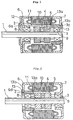
- Fig. 1 An embodiment of the present invention will now be described with reference to Fig. 1 in which the same reference numerals are used to indicate the like members or components shown in Figs. 9 to 12.
- the front casing 6 is the same as that shown in Figs. 11 and 12 but a sleeve-like bush 13 made of non-magnetic material is fitted into the rear casing 7.
- a stepped portion 13a is formed in the outer circumferential portion on the inner side of the bush 13.
- the inner circumferential portion of the stator core 10 is retained by the stepped portion 13a.
- the rear bearing 9 is supported by the inner circumference of the bush 13.
- the bush 13 is made of aluminum alloy or any other non-magnetic metal or is molded of resin.
- a recessed groove 13b is formed at portions in the vicinity of the end of the bush 13.
- the bush 13 is fitted into a hole edge 7d of the casing 7 at the recessed groove 13b.
- the bush 13 is press-fitted and fixed by applying a force directed inwardly to the outer portion of the bush 13.
- the bush 13 is fixed with adhesive or by welding after being pressed and fitted.
- the bush 13 is formed integrally with the casing 7.
- Fig. 2 shows an embodiment in which the recessed groove 13b of the bush 13 is fitted in a hole edge 6d of the front casing 6, and the inner circumferential portion of the stator core 10 is supported to the front edge of the bush 13.
- the fixture structure of the bush 13 that has been fitted and other structures are the same as those of Fig. 1.
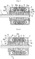
- the bush 13 is mounted on either, front casing 6 or rear casing 7.
- the bushes 13 may be mounted on both the front and rear casings 6 and 7.
- Fig. 3 shows an embodiment showing the above case.
- the bushes 13 are mounted on the front and rear casings, a cross-sectional shapes of the casings 6 and 7.
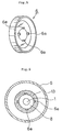
- Fig. 4 is a longitudinal sectional view showing the above embodiment.
- Fig. 5 is a perspective view showing a casing 6 of the two casings 6 and 7. Incidentally, since the structure of the casing 7 is the same as that of the casing 6, a showing and an explanation thereof are omitted. In this embodiment, an inner end of the casing 6 is extended inwardly to form a plurality of projected piece 6e along the rotary shaft 1 (see Fig. 5).
- Synthetic resin is filled in between the projected piece 6e and the stator core 10 circumferentially to mold the bush 13 so as to fixed to the casing 6.
- the number of the projected pieces 6e is four, but it is possible to increase the number of the projected pieces. In this case, it is possible to enhance a mechanical strength of the molded portion.
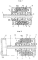
- Fig. 7 shows an embodiment in which the structure which is the same as that shown in Fig. 4 is applied to the rear casing 7.
- Fig. 8 shows an embodiment in which the above structure is applied to both the front and rear casings 6 and 7.
- the structure shown in Figs. 4 and 7 supports one end of the inner circumferential portion of the stator core 10, whereas the structure shown in Fig. 8 supports both ends of the inner circumferential portion of the stator core 10. In this case, any displacement due to vibration or the like may be avoided for a long period of time.
- the rotor 5 is intermittently rotated by intermittently feeding current to the stator coil 11 as shown in Figs. 9 to 11. Since the inner circumferential portion of the stator core 10 is supported by the bush 13, the gap between the outer circumferential portion of the rotor 5 and the inner circumferential portion of the stator core 10 may be maintained correctly so that the performance of rotation may be kept at a high level.
- the bush 13 made of non-magnetic material is fixed to the casing 6.
- the present invention is not limited to this structure. According to the present invention, it is possible to fix the bush 13 to the stator core 10.
- Fig. 9 shows an embodiment in the above case.
- the bush 13 made of non-magnetic material is mounted on one side of the stator core 10 at the stepped portion 13a and fixed thereto to retain the bearing 8. After the bush 13 has been mounted, as shown in Fig. 10, the end portion of the bush 13 is fitted into a hole edge 6d of the casing 6 for completing the mounting work.
- the bush 13 is mounted on the side of the bearing 8 of the stator core 10.
- the present invention is not limited to this arrangement. It is possible to mount on the side of the bearing 9 as shown in Fig. 11. Furthermore, it is possible to mount the bushes 13 on both sides of the stator core 10 as shown in Fig. 12. In the embodiment shown in Fig. 11, the bearing 9 is supported by the bush 13 and in the embodiment shown in Fig. 12, the bearings 8 and 9 are supported by the two bushes 13, respectively.
- the material of the bushes 13 non-magnetic metallic material is desirable as mentioned above and as to the method to fix the bush 13 to the stator core 10, it may be fixed to the stator core 10 with adhesives or by press-fitting.
- the bushes 13 may be made of thermoplastic resin, thereby to be fixed to the stator core 10.
- the casing may be formed by pressing a metal plate, molding a resin or die-casting in aluminum alloy. Also, with respect to the method of mounting the casing 6 on a sub-assembly in which the bush 13 is mounted on the stator core 10, the casing 6 is press-fitted into the bush 13 and fixed by screws or by press-fitting. In another method, it is possible to mount the casing 6 onto the bush 13 with adhesives or by welding. Furthermore, it is possible to weld and bond the casing 6 to the stator core 10.
- the stepping motor is thus constructed according to any one of the first, second, sixth and seventh aspects of the invention, it is possible to make the casing with ease and at low cost by pressing. Since the bearing and the stator core or the casing are supported by the bush interposed into the casing or the stator core, the gap between the outer circumference of the rotor and the inner circumference of the stator core may be kept constant. Accordingly, it is possible to obtain a stepping motor having a stable performance. Then, since the bush is made of non-magnetic material, there is no fear that the magnetism generated by the stator core leaks to the casing made of the metal plate to thereby degrade the motor performance.
- the bush is made of non-magnetic metal, it is considerably easy to mount the bush onto the casing or the stator core by press-fitting or the like. Also, according to the fourth, fifth and ninth aspects of the present invention, since the bush is made of synthetic resin having thermoplasticity, the manufacture thereof is easy to enhance the productivity.
Abstract
Description
- The present invention relates to a stepping motor used in an OA machine for processing image information such as a facsimile, an ink jet printer, a laser beam printer, a copying machine or the like.
- In a stepping motor used in such as the above OA machine, there has been demanded that a resolving power and a noiseless property should be enhanced to attain a low vibration and a low noise while aiming at reducing cost therefor that is an absolute condition.
- The conventional technology disclosed in Japanese Patent Application Laid-Open No. Hei 8-298739 will be described with reference to Fig. 13. A
rotor 5 composed of a pair of disc-like rotor cores magnet 4 interposed therebetween is mounted on arotary shaft 1. Therotary shaft 1 is supported bybearings portions front casing 6 andrear casing 7, respectively. Steppedportions rear casings stator core 10 is supported by thestepped portions stator coil 11 is wound around thestator core 10 and is connected to a drive circuit (not shown). - In this stepping motor, current is intermittently supplied from the drive circuit (not shown) to the
stator core 11 to thereby intermittently rotate therotor 5. The rotational property of this arrangement depends upon uniformity of a fine gap formed between an inner diameter of thestator core 10 and an outer diameter of therotor 5. In the above-described arrangement, since the outer circumferential portion of thestator core 10 is retained by thecasings casings stator core 10 to thecasings stator core 10 before the assembling work. As a result, the fine gap between the inner diameter of thestator core 10 and the outer diameter of therotor 5 becomes an eccentric gap, sometimes resulting in non-uniformity. - For this reason, the arrangement suffers from a problem that the dimensional precision of the outer diameter to the inner diameter of the
stator core 10 and the dimensional precision of the outer circumferential fitting portions of the casings to the dimension of the fitting portions of thebearings - In order to solve this problem, the arrangement is modified in design in a stepping motor as shown in Fig. 14. In this stepping motor, the
stepped portions 6c and 7c are formed on the outer circumferential side of the projectedportions rear casings stator core 10 is received by thestepped portions 6c and 7c. If such an arrangement is adopted, the inner circumferential portion of thestator core 10 is directly supported. It is therefore possible to remove the eccentric factor to be generated between the inner diameter of thestator core 10 and the outer diameter of therotor 5. Thus, it is possible to solve the above-noted problem. - Fig. 15 shows a design for the purpose of reducing the manufacture cost. The shape of the design is simplified in which, after the
front casing 6 has been cast in aluminum, thefront casing 6 is machined. Thefront casing 6 is shaped by metal-plate pressing. With this structure, it is possible to reduce the cost of thecasings stator core 10 and the outer diameter of therotor 5 is the same as that shown in Fig. 13. Incidentally, though the structure shown in Fig. 15 exemplifies the structure in which theplate 12 is arranged in front of thefront casing 6, theplate 12 may not be used. - Fig. 16 shows a design for the purpose of enhancing the rotational gap precision of the design shown in Fig. 15. Bearing fitting portions of the metal plates are extended and the
stepped portions 6c and 7c are formed in the extended portions. The inner circumferential portion of thestator core 10 is received by thestepped portions 6c and 7c. However, this structure suffers from a defect that, as shown by the arrows in Fig. 16, the magnetic field generated in thestator core 10 leaks to thecasings casings stator core 10. It is impossible to take a structure in which thestator core 10 is held in the inner diameter portion. - In view of the above-noted defects, an object of the present invention is to provide a structure in which the above-noted defects do not occur even in the case where the casings are made by pressing metal plate.
- According to a first aspect of the present invention, in a stepping motor having a structure in which a stator core is disposed outside of a rotor mounted on a rotary shaft, and a rear portion and a front portion of the rotary shaft are supported by bearings mounted on casings provided on the front and rear sides of the stator core, respectively, the stepping motor is characterized in that the casings are press-formed with a metal plate, a bush made of non-magnetic material is mounted on at least one of the casings, and the stator core is supported by the bush.
- Also, according to a second aspect of the present invention, in the first aspect of the present invention, the bush supports at least one of the bearings.
- Also, according to a third aspect of the present invention, in the first or second aspect of the present invention, the bush is made of non-magnetic metallic material, and fixed to at least one of the casings by either adhesives or press-fitting.
- Also, according to a fourth aspect of the present invention, in the first or second aspect of the present invention, a plurality of projected pieces directed inwardly for receiving an outer circumference of at least one of the bearings is formed integrally with a portion of at least one of the casings onto which at least one of the bearing is mounted, synthetic resin is filled in between the projected pieces and the stator core circumferentially so that the bush is mounted.
- Furthermore, according to a fifth aspect of the present invention, in the first or second aspect of the present invention, the bush which is made of thermoplastic resin is fixed to at least one of the casings.
- Then, according a sixth aspect of the present invention, in a stepping motor in which a stator core is disposed outside of a rotor mounted on a rotary shaft, and a rear portion and a front portion of the rotary shaft are supported to bearings mounted on casings provided on the front and rear sides of the stator core, respectively, the stepping motor is characterized in that a bush made of non-magnetic material is mounted on one of the stator cores, and at least one of the casings is mounted on the bush.
- Also according to a seventh aspect of the present invention, in the sixth aspect of the present invention, the bush supports at least one of the bearings.
- According to an eighth aspect of the present invention, in the sixth or seventh aspect of the present invention, the bush is made of non-magnetic metallic material, and fixed to at least one of the stator cores by either adhesives or press-fitting.
- According to a ninth aspect of the present invention, in the sixth or seventh aspect of the present invention, the bush is made of thermoplastic resin and fixed to at least one of the stator cores with thermoplastic resin.
- With such an arrangement, since the bush made of non-magnetic metallic material or synthetic resin is bonded with the inner circumferential portion of the stator core, an eccentric factor between the inner circumferential portion of the stator core and the outer circumferential portion of the rotor is removed to thereby enhance the rotational performance of rotation, and in addition to overcome the risk that the magnetism generated in the stator core leaks to the casings made of the metal plate.
- In the accompanying drawings:
- Fig. 1 is a longitudinal sectional view showing one example of an embodiment of the present invention;
- Fig. 2 is a longitudinal sectional view showing another example of an embodiment of the present invention;
- Fig. 3 is a longitudinal sectional view showing still another example of an embodiment of the present invention;
- Fig. 4 is a longitudinal sectional view showing still another example of an embodiment of the present invention;
- Fig. 5 is a perspective view showing projected pieces formed on a casing;
- Fig. 6 is a cross-sectional view showing a part taken along the line A-A of Fig. 4;
- Fig. 7 is a longitudinal sectional view showing still another example of an embodiment of the present invention;
- Fig. 8 is a longitudinal sectional view showing still another example of an embodiment of the present invention;
- Fig. 9 is a longitudinal sectional view showing still another example of an embodiment of the present invention;
- Fig. 10 is a longitudinal sectional view showing a condition in which the casing is assembled in Fig. 9;
- Fig. 11 is a longitudinal sectional view showing still another example of an embodiment of the present invention;
- Fig. 12 is a longitudinal sectional view showing still another example of an embodiment of the present invention;
- Fig. 13 is a longitudinal sectional view showing a example of a conventional stepping motor;
- Fig. 14 is a longitudinal sectional view showing another example of a conventional stepping motor;
- Fig. 15 is a longitudinal sectional view showing another example of a conventional stepping motor; and
- Fig. 16 is a longitudinal sectional view showing still another example of a conventional stepping motor.
-
- An embodiment of the present invention will now be described with reference to Fig. 1 in which the same reference numerals are used to indicate the like members or components shown in Figs. 9 to 12. In this embodiment, the
front casing 6 is the same as that shown in Figs. 11 and 12 but a sleeve-like bush 13 made of non-magnetic material is fitted into therear casing 7. A steppedportion 13a is formed in the outer circumferential portion on the inner side of thebush 13. The inner circumferential portion of thestator core 10 is retained by the steppedportion 13a. Incidentally, therear bearing 9 is supported by the inner circumference of thebush 13. - The
bush 13 is made of aluminum alloy or any other non-magnetic metal or is molded of resin. A recessedgroove 13b is formed at portions in the vicinity of the end of thebush 13. Thebush 13 is fitted into ahole edge 7d of thecasing 7 at the recessedgroove 13b. In the case where thebush 13 is made of metal, after thebush 13 has been pressed and fitted, thebush 13 is press-fitted and fixed by applying a force directed inwardly to the outer portion of thebush 13. In the case where thebush 13 is molded of resin, thebush 13 is fixed with adhesive or by welding after being pressed and fitted. Furthermore, in the case of thebush 13 is made of thermoplastic resin, thebush 13 is formed integrally with thecasing 7. - Fig. 2 shows an embodiment in which the recessed
groove 13b of thebush 13 is fitted in ahole edge 6d of thefront casing 6, and the inner circumferential portion of thestator core 10 is supported to the front edge of thebush 13. The fixture structure of thebush 13 that has been fitted and other structures are the same as those of Fig. 1. - In the foregoing two embodiments, the
bush 13 is mounted on either,front casing 6 orrear casing 7. However, the present invention is not limited thereto or thereby. Thebushes 13 may be mounted on both the front andrear casings bushes 13 are mounted on the front and rear casings, a cross-sectional shapes of thecasings - In the embodiments shown in Figs. 1 to 3, the
bushes 13 are made separately from thecasings bushes 13 may be formed of synthetic resin having thermoplasticity for being fixed to thecasings casing 6 of the twocasings casing 7 is the same as that of thecasing 6, a showing and an explanation thereof are omitted. In this embodiment, an inner end of thecasing 6 is extended inwardly to form a plurality of projectedpiece 6e along the rotary shaft 1 (see Fig. 5). Synthetic resin is filled in between the projectedpiece 6e and thestator core 10 circumferentially to mold thebush 13 so as to fixed to thecasing 6. Incidentally, in Figs. 5 and 6, the number of the projectedpieces 6e is four, but it is possible to increase the number of the projected pieces. In this case, it is possible to enhance a mechanical strength of the molded portion. - Fig. 7 shows an embodiment in which the structure which is the same as that shown in Fig. 4 is applied to the
rear casing 7. Furthermore, Fig. 8 shows an embodiment in which the above structure is applied to both the front andrear casings stator core 10, whereas the structure shown in Fig. 8 supports both ends of the inner circumferential portion of thestator core 10. In this case, any displacement due to vibration or the like may be avoided for a long period of time. - In the structures shown in Figs. 4 to 8, since the
casings bearings bearings casings bushes 13 are made of synthetic resin, there is an advantage that no undesirable magnetic circuit is generated. - Also in the foregoing embodiments, the
rotor 5 is intermittently rotated by intermittently feeding current to thestator coil 11 as shown in Figs. 9 to 11. Since the inner circumferential portion of thestator core 10 is supported by thebush 13, the gap between the outer circumferential portion of therotor 5 and the inner circumferential portion of thestator core 10 may be maintained correctly so that the performance of rotation may be kept at a high level. - In the foregoing embodiments, the
bush 13 made of non-magnetic material is fixed to thecasing 6. However, the present invention is not limited to this structure. According to the present invention, it is possible to fix thebush 13 to thestator core 10. Fig. 9 shows an embodiment in the above case. Thebush 13 made of non-magnetic material is mounted on one side of thestator core 10 at the steppedportion 13a and fixed thereto to retain thebearing 8. After thebush 13 has been mounted, as shown in Fig. 10, the end portion of thebush 13 is fitted into ahole edge 6d of thecasing 6 for completing the mounting work. - In Fig. 10, the
bush 13 is mounted on the side of thebearing 8 of thestator core 10. The present invention is not limited to this arrangement. It is possible to mount on the side of thebearing 9 as shown in Fig. 11. Furthermore, it is possible to mount thebushes 13 on both sides of thestator core 10 as shown in Fig. 12. In the embodiment shown in Fig. 11, thebearing 9 is supported by thebush 13 and in the embodiment shown in Fig. 12, thebearings bushes 13, respectively. - With respect to the material of the
bushes 13 non-magnetic metallic material is desirable as mentioned above and as to the method to fix thebush 13 to thestator core 10, it may be fixed to thestator core 10 with adhesives or by press-fitting. Other than adhesives or press-fitting, thebushes 13 may be made of thermoplastic resin, thereby to be fixed to thestator core 10. - The casing may be formed by pressing a metal plate, molding a resin or die-casting in aluminum alloy. Also, with respect to the method of mounting the
casing 6 on a sub-assembly in which thebush 13 is mounted on thestator core 10, thecasing 6 is press-fitted into thebush 13 and fixed by screws or by press-fitting. In another method, it is possible to mount thecasing 6 onto thebush 13 with adhesives or by welding. Furthermore, it is possible to weld and bond thecasing 6 to thestator core 10. - According to the present invention, since the stepping motor is thus constructed according to any one of the first, second, sixth and seventh aspects of the invention, it is possible to make the casing with ease and at low cost by pressing. Since the bearing and the stator core or the casing are supported by the bush interposed into the casing or the stator core, the gap between the outer circumference of the rotor and the inner circumference of the stator core may be kept constant. Accordingly, it is possible to obtain a stepping motor having a stable performance. Then, since the bush is made of non-magnetic material, there is no fear that the magnetism generated by the stator core leaks to the casing made of the metal plate to thereby degrade the motor performance.
- According to the third and eighth aspects of the present invention, since the bush is made of non-magnetic metal, it is considerably easy to mount the bush onto the casing or the stator core by press-fitting or the like. Also, according to the fourth, fifth and ninth aspects of the present invention, since the bush is made of synthetic resin having thermoplasticity, the manufacture thereof is easy to enhance the productivity.
- Various details of the invention may be changed without departing from its spirit nor its scope. Furthermore, the foregoing description of the embodiments according to the present invention is provided for the purpose of illustration only, and not for the purpose of limiting the invention as defined by the appended claims and their equivalents.
Claims (9)
- A stepping motor having a structure in which a stator core is disposed outside of a rotor mounted on a rotary shaft, and a rear portion and a front portion of the rotary shaft are supported by bearings mounted on casings provided on the front and rear sides of the stator core, respectively, wherein the casings are press-formed with a metal plate, a bush made of non-magnetic material is fixed to on at least one of the casings, and the stator core is supported by the bush.
- The stepping motor according to claim 1, wherein the bush supports at least one of the bearings.
- The stepping motor according to claim 1 or 2, wherein the bush is made of non-magnetic metallic material, and fixed to at least one of the casings by one of adhesives and press-fitting.
- The stepping motor according to claim 1 or 2, wherein a plurality of projected pieces directed inwardly for receiving an outer circumference of at least one of the bearings is formed integrally with a portion of at least one of the casings onto which at least one of the bearing is mounted, synthetic resin is filled in between the projected pieces and the stator core circumferentially so that the bush is mounted.
- The stepping motor according to claim 1 or 2, wherein the bush is formed integrally with at least one of the casings with thermoplastic resin.
- A stepping motor having a structure in which a stator core is disposed outside of a rotor mounted on a rotary shaft, and a rear portion and a front portion of the rotary shaft are supported to bearings mounted on casings provided on the front and rear sides of the stator core, respectively, wherein a bush made of non-magnetic material is fixed to one of the stator cores, and at least one of the casings is supported by the bush.
- The stepping motor according to claim 6, wherein the bush supports at least one of the bearings.
- The stepping motor according to claim 6 or 7, wherein the bush is made of non-magnetic metal material, and fixed to at least one of the stator cores by one of adhesives and press-fitting.
- The stepping motor according to claim 6 or 7, wherein the bush is made of thermoplastic resin and fixed to at least one of the stator cores.
Applications Claiming Priority (4)
| Application Number | Priority Date | Filing Date | Title |
|---|---|---|---|
| JP12850498 | 1998-05-12 | ||
| JP12850498 | 1998-05-12 | ||
| JP10210346A JP2990432B1 (en) | 1998-05-12 | 1998-07-09 | Stepping motor |
| JP21034698 | 1998-07-09 |
Publications (3)
| Publication Number | Publication Date |
|---|---|
| EP0957562A2 true EP0957562A2 (en) | 1999-11-17 |
| EP0957562A3 EP0957562A3 (en) | 2001-10-04 |
| EP0957562B1 EP0957562B1 (en) | 2004-09-29 |
Family
ID=26464151
Family Applications (1)
| Application Number | Title | Priority Date | Filing Date |
|---|---|---|---|
| EP99103399A Expired - Lifetime EP0957562B1 (en) | 1998-05-12 | 1999-02-22 | Stepping motor |
Country Status (4)
| Country | Link |
|---|---|
| US (1) | US5945759A (en) |
| EP (1) | EP0957562B1 (en) |
| JP (1) | JP2990432B1 (en) |
| DE (1) | DE69920573T2 (en) |
Cited By (1)
| Publication number | Priority date | Publication date | Assignee | Title |
|---|---|---|---|---|
| EP2410635A3 (en) * | 2010-07-22 | 2017-03-15 | Globe Motors, Inc. | Frameless electric motor assembly |
Families Citing this family (32)
| Publication number | Priority date | Publication date | Assignee | Title |
|---|---|---|---|---|
| US6211587B1 (en) * | 1998-11-12 | 2001-04-03 | Hitachi, Ltd. | Electric rotating machine |
| JP3736166B2 (en) * | 1999-01-06 | 2006-01-18 | セイコーエプソン株式会社 | Stepping motor |
| US6252321B1 (en) * | 1999-06-23 | 2001-06-26 | General Electric Company | Endshield assembly with alignable bearing for an electric motor |
| DE10051403A1 (en) * | 2000-10-17 | 2002-06-13 | Minebea Co Ltd | Rotor assembly for an electric motor and internal rotor electric motor |
| FR2819117B1 (en) * | 2000-12-21 | 2004-10-29 | Valeo Equip Electr Moteur | ALTERNATOR WITH CONDUCTIVE ELEMENTS FOR A MOTOR VEHICLE |
| FR2818821B1 (en) * | 2000-12-21 | 2003-05-16 | Valeo Equip Electr Moteur | ALTERNATOR FOR MOTOR VEHICLE |
| FR2820896B1 (en) * | 2000-12-21 | 2003-06-20 | Valeo Equip Electr Moteur | ALTERNATOR FOR MOTOR VEHICLE |
| US7143462B2 (en) | 2002-09-20 | 2006-12-05 | Colgate-Palmolive Company | Oral care implement |
| JP3944825B2 (en) * | 2001-11-16 | 2007-07-18 | ミネベア株式会社 | Sealed structure motor and method of using the same |
| CN1331298C (en) * | 2002-04-10 | 2007-08-08 | 卢克摩擦片和离合器两合公司 | Drive arrangement with a fixed bearing |
| JP3987413B2 (en) * | 2002-10-22 | 2007-10-10 | ミネベア株式会社 | motor |
| FR2841701B1 (en) * | 2003-03-24 | 2008-06-13 | Valeo Equip Electr Moteur | ALTERNATOR FOR MOTOR VEHICLE |
| JP4280542B2 (en) * | 2003-04-30 | 2009-06-17 | 日本電産コパル株式会社 | Stepping motor |
| US7109626B2 (en) * | 2004-02-06 | 2006-09-19 | Emerson Electric Co. | Compact dynamoelectric machine |
| JP4000144B2 (en) * | 2004-12-15 | 2007-10-31 | 山洋電気株式会社 | Rotor for hybrid type stepping motor and manufacturing method thereof |
| DE102005022793B3 (en) * | 2005-05-12 | 2006-06-29 | Aktiebolaget Skf | Rotor bearing for an electrical machine has bearing mounted on plastic body in stator housing and second bearing on plastic body in pressed housing cover |
| FR2943863B1 (en) * | 2009-03-31 | 2013-04-12 | Somfy Sas | TUBULAR TYPE INDUCTION MOTOR WITH TWO DIRECTION OF ROTATION FOR DOMOTIC APPLICATIONS. |
| KR101016607B1 (en) * | 2009-07-03 | 2011-02-22 | 주식회사 모아텍 | Step motor |
| US8278803B2 (en) * | 2009-08-14 | 2012-10-02 | Lin Engineering | Motor end cap positioning element for maintaining rotor-stator concentricity |
| DE102012100158A1 (en) * | 2011-01-11 | 2012-07-12 | Denso Corporation | Stator for rotating electrical machines and method of making same |
| CN103915919B (en) * | 2011-01-11 | 2016-11-30 | 株式会社电装 | For the stator of electric rotating machine and the method that manufactures described stator |
| FR2981224B1 (en) * | 2011-10-06 | 2016-01-15 | Somfy Sas | INDUCTION MOTOR CAPABLE OF BEING LOOSE IN A TUBULAR ACTUATOR AND METHOD FOR ASSEMBLING THE SAME |
| US20130154406A1 (en) * | 2011-12-19 | 2013-06-20 | Samsung Electro-Mechanics Co., Ltd. | Switched reluctance motor assembly |
| KR20140008483A (en) * | 2012-07-10 | 2014-01-21 | 주식회사 만도 | Structure for motor |
| JP5936990B2 (en) * | 2012-10-31 | 2016-06-22 | 日本ピストンリング株式会社 | Rotating electric machine |
| DE102012221596A1 (en) * | 2012-11-26 | 2014-05-28 | Robert Bosch Gmbh | Stator with an encapsulation and electric machine with the stator |
| JP2016086555A (en) * | 2014-10-27 | 2016-05-19 | トヨタ自動車株式会社 | Electrical equipment |
| DE102014018745A1 (en) * | 2014-12-16 | 2016-06-16 | Daimler Ag | Electric machine, in particular for a motor vehicle, and method for producing such an electric machine |
| KR102452161B1 (en) * | 2015-08-03 | 2022-10-11 | 엘지이노텍 주식회사 | Motor |
| EP3229350B1 (en) * | 2016-04-08 | 2021-06-23 | Black & Decker Inc. | Brushless motor for a power tool |
| JP7264717B2 (en) * | 2019-05-15 | 2023-04-25 | ファナック株式会社 | Electric motor with a housing fixed to the end face of the stator core |
| DE202019106968U1 (en) * | 2019-12-13 | 2021-03-16 | C. & E. Fein Gmbh | Electric motor for a hand machine tool |
Citations (4)
| Publication number | Priority date | Publication date | Assignee | Title |
|---|---|---|---|---|
| JPS6091852A (en) * | 1983-10-20 | 1985-05-23 | Ricoh Elemex Corp | Rotary motor |
| EP0302116A1 (en) * | 1987-02-17 | 1989-02-08 | Fanuc Ltd. | Method of inserting rotor of motor and motor suitable therefor |
| EP0406431A1 (en) * | 1988-10-07 | 1991-01-09 | Fanuc Ltd. | Bearing retainer structure for electric motors |
| EP1018796A2 (en) * | 1999-01-06 | 2000-07-12 | Seiko Epson Corporation | Stepping motor |
Family Cites Families (2)
| Publication number | Priority date | Publication date | Assignee | Title |
|---|---|---|---|---|
| JPS59135087U (en) * | 1983-02-26 | 1984-09-10 | シナノケンシ株式会社 | Permanent magnet step motor |
| JPH08298739A (en) * | 1995-04-25 | 1996-11-12 | Minebea Co Ltd | Stepping motor |
-
1998
- 1998-07-09 JP JP10210346A patent/JP2990432B1/en not_active Expired - Fee Related
-
1999
- 1999-01-25 US US09/236,472 patent/US5945759A/en not_active Expired - Lifetime
- 1999-02-22 EP EP99103399A patent/EP0957562B1/en not_active Expired - Lifetime
- 1999-02-22 DE DE69920573T patent/DE69920573T2/en not_active Expired - Fee Related
Patent Citations (4)
| Publication number | Priority date | Publication date | Assignee | Title |
|---|---|---|---|---|
| JPS6091852A (en) * | 1983-10-20 | 1985-05-23 | Ricoh Elemex Corp | Rotary motor |
| EP0302116A1 (en) * | 1987-02-17 | 1989-02-08 | Fanuc Ltd. | Method of inserting rotor of motor and motor suitable therefor |
| EP0406431A1 (en) * | 1988-10-07 | 1991-01-09 | Fanuc Ltd. | Bearing retainer structure for electric motors |
| EP1018796A2 (en) * | 1999-01-06 | 2000-07-12 | Seiko Epson Corporation | Stepping motor |
Non-Patent Citations (1)
| Title |
|---|
| PATENT ABSTRACTS OF JAPAN vol. 009, no. 240 (E-345), 26 September 1985 (1985-09-26) & JP 60 091852 A (RIKOO TOKEI KK), 23 May 1985 (1985-05-23) * |
Cited By (1)
| Publication number | Priority date | Publication date | Assignee | Title |
|---|---|---|---|---|
| EP2410635A3 (en) * | 2010-07-22 | 2017-03-15 | Globe Motors, Inc. | Frameless electric motor assembly |
Also Published As
| Publication number | Publication date |
|---|---|
| DE69920573D1 (en) | 2004-11-04 |
| JP2000037068A (en) | 2000-02-02 |
| JP2990432B1 (en) | 1999-12-13 |
| US5945759A (en) | 1999-08-31 |
| EP0957562A3 (en) | 2001-10-04 |
| EP0957562B1 (en) | 2004-09-29 |
| DE69920573T2 (en) | 2006-02-23 |
Similar Documents
| Publication | Publication Date | Title |
|---|---|---|
| US5945759A (en) | Stepping motor | |
| US5500994A (en) | Method of manufacturing a rotor | |
| US7408280B2 (en) | Rotor of rotary electric machine | |
| JP4462525B2 (en) | Hydrodynamic air bearing type polygon scanner and processing method thereof | |
| US6342739B1 (en) | Small-sized motor and method of manufacturing the same | |
| JP2004236390A (en) | Small-sized brushless motor | |
| US7339299B2 (en) | Electric actuator and motor used therein | |
| JPWO2006008964A1 (en) | Magnet fixing structure of rotating electric machine | |
| US4796352A (en) | AC servomotor and a method of manufacturing the same | |
| JP5920319B2 (en) | Rotor fixing structure and rotating electric machine | |
| JP2003158849A (en) | Sealed motor and usage thereof | |
| WO2014061156A1 (en) | Electric motor and manufacturing method | |
| US20050110358A1 (en) | Electric rotating machine and manufacturing process thereof | |
| JP4622897B2 (en) | Rotating electric machine stator | |
| US7053518B2 (en) | Rotor for dynamo-electric machine | |
| JPH10336972A (en) | Electric rotating machine | |
| JPH0842668A (en) | Car transmission and fastener member for transmission | |
| JP4498050B2 (en) | Inner rotor type brushless motor | |
| CN220754622U (en) | Stepping motor actuator | |
| US20230034210A1 (en) | Rotor assembly, method for manufacturing rotor assembly, and motor including rotor assembly | |
| JP4033332B2 (en) | Stepping motor | |
| JP2018129933A (en) | Motor and method for manufacturing motor | |
| JP2002027726A (en) | Stepping motor | |
| US11108288B2 (en) | Rotor and motor | |
| JP4033283B2 (en) | DYNAMIC PRESSURE AIR BEARING TYPE OPTICAL DEFLECTOR, METHOD OF PROCESSING THE ROTATING BODY, AND RECYCLING METHOD OF COMPONENT FOR DYNAMIC PRESSURE AIR BEARING TYPE OPTICAL DEFLECTOR |
Legal Events
| Date | Code | Title | Description |
|---|---|---|---|
| PUAI | Public reference made under article 153(3) epc to a published international application that has entered the european phase |
Free format text: ORIGINAL CODE: 0009012 |
|
| AK | Designated contracting states |
Kind code of ref document: A2 Designated state(s): AT BE CH CY DE DK ES FI FR GB GR IE IT LI LU MC NL PT SE Kind code of ref document: A2 Designated state(s): DE FR GB IT |
|
| AX | Request for extension of the european patent |
Free format text: AL;LT;LV;MK;RO;SI |
|
| PUAL | Search report despatched |
Free format text: ORIGINAL CODE: 0009013 |
|
| AK | Designated contracting states |
Kind code of ref document: A3 Designated state(s): AT BE CH CY DE DK ES FI FR GB GR IE IT LI LU MC NL PT SE |
|
| AX | Request for extension of the european patent |
Free format text: AL;LT;LV;MK;RO;SI |
|
| 17P | Request for examination filed |
Effective date: 20011213 |
|
| AKX | Designation fees paid |
Free format text: DE FR GB IT |
|
| 17Q | First examination report despatched |
Effective date: 20030319 |
|
| GRAP | Despatch of communication of intention to grant a patent |
Free format text: ORIGINAL CODE: EPIDOSNIGR1 |
|
| GRAS | Grant fee paid |
Free format text: ORIGINAL CODE: EPIDOSNIGR3 |
|
| GRAA | (expected) grant |
Free format text: ORIGINAL CODE: 0009210 |
|
| AK | Designated contracting states |
Kind code of ref document: B1 Designated state(s): DE FR GB IT |
|
| REG | Reference to a national code |
Ref country code: GB Ref legal event code: FG4D |
|
| REF | Corresponds to: |
Ref document number: 69920573 Country of ref document: DE Date of ref document: 20041104 Kind code of ref document: P |
|
| ET | Fr: translation filed | ||
| PLBE | No opposition filed within time limit |
Free format text: ORIGINAL CODE: 0009261 |
|
| STAA | Information on the status of an ep patent application or granted ep patent |
Free format text: STATUS: NO OPPOSITION FILED WITHIN TIME LIMIT |
|
| 26N | No opposition filed |
Effective date: 20050630 |
|
| PGFP | Annual fee paid to national office [announced via postgrant information from national office to epo] |
Ref country code: DE Payment date: 20090219 Year of fee payment: 11 |
|
| PGFP | Annual fee paid to national office [announced via postgrant information from national office to epo] |
Ref country code: GB Payment date: 20090217 Year of fee payment: 11 |
|
| PGFP | Annual fee paid to national office [announced via postgrant information from national office to epo] |
Ref country code: IT Payment date: 20090216 Year of fee payment: 11 |
|
| PGFP | Annual fee paid to national office [announced via postgrant information from national office to epo] |
Ref country code: FR Payment date: 20090213 Year of fee payment: 11 |
|
| GBPC | Gb: european patent ceased through non-payment of renewal fee |
Effective date: 20100222 |
|
| REG | Reference to a national code |
Ref country code: FR Ref legal event code: ST Effective date: 20101029 |
|
| PG25 | Lapsed in a contracting state [announced via postgrant information from national office to epo] |
Ref country code: FR Free format text: LAPSE BECAUSE OF NON-PAYMENT OF DUE FEES Effective date: 20100301 |
|
| PG25 | Lapsed in a contracting state [announced via postgrant information from national office to epo] |
Ref country code: DE Free format text: LAPSE BECAUSE OF NON-PAYMENT OF DUE FEES Effective date: 20100901 |
|
| PG25 | Lapsed in a contracting state [announced via postgrant information from national office to epo] |
Ref country code: GB Free format text: LAPSE BECAUSE OF NON-PAYMENT OF DUE FEES Effective date: 20100222 Ref country code: IT Free format text: LAPSE BECAUSE OF NON-PAYMENT OF DUE FEES Effective date: 20100222 |