EP0957504A2 - Elektronenstrahlerzeugungsvorrichtungen - Google Patents
Elektronenstrahlerzeugungsvorrichtungen Download PDFInfo
- Publication number
- EP0957504A2 EP0957504A2 EP99303554A EP99303554A EP0957504A2 EP 0957504 A2 EP0957504 A2 EP 0957504A2 EP 99303554 A EP99303554 A EP 99303554A EP 99303554 A EP99303554 A EP 99303554A EP 0957504 A2 EP0957504 A2 EP 0957504A2
- Authority
- EP
- European Patent Office
- Prior art keywords
- arrangement
- electrode
- cathode
- flexible member
- mount
- Prior art date
- Legal status (The legal status is an assumption and is not a legal conclusion. Google has not performed a legal analysis and makes no representation as to the accuracy of the status listed.)
- Withdrawn
Links
Images

Classifications
-
- H—ELECTRICITY
- H01—ELECTRIC ELEMENTS
- H01J—ELECTRIC DISCHARGE TUBES OR DISCHARGE LAMPS
- H01J23/00—Details of transit-time tubes of the types covered by group H01J25/00
- H01J23/02—Electrodes; Magnetic control means; Screens
- H01J23/06—Electron or ion guns
- H01J23/065—Electron or ion guns producing a solid cylindrical beam
-
- H—ELECTRICITY
- H01—ELECTRIC ELEMENTS
- H01J—ELECTRIC DISCHARGE TUBES OR DISCHARGE LAMPS
- H01J2225/00—Transit-time tubes, e.g. Klystrons, travelling-wave tubes, magnetrons
- H01J2225/02—Tubes with electron stream modulated in velocity or density in a modulator zone and thereafter giving up energy in an inducing zone, the zones being associated with one or more resonators
- H01J2225/04—Tubes having one or more resonators, without reflection of the electron stream, and in which the modulation produced in the modulator zone is mainly density modulation, e.g. Heaff tube
Definitions
- This invention relates to electron gun arrangements and more particularly, but not exclusively, to arrangements suitable for use in inductive output tubes (IOTs).
- IOTs inductive output tubes
- the present invention seeks to provides an electron gun arrangement which permits close spacing to be maintained with accuracy between the cathode and adjacent electrode or electrodes and also provides a good mechanical construction.
- an electron gun arrangement comprising: a vacuum envelope containing a cathode and an electrode located in front of the cathode; an electrode support mounted on a mount of low thermal expansivity; and a flexible member making a vacuum seal with the mount and with a component forming part of the vacuum envelope.
- the r.f. part of the arrangement are separated from the mechanical, vacuum seal aspect of the design.
- the vacuum envelope is typically formed from several separate sections, some of which may provide support for parts of the electron gun and also provide means for applying electrical potentials to electrodes of the electron gun which are joined together by vacuum seals.
- the electron gun arrangement becomes hot and components of the vacuum envelope and the gun assembly itself expand to an extent depending on the thermal expansivity of the materials used in the construction.
- a flexible member is included in the arrangement as part of the vacuum envelope to allow for thermal expansion. If all the components making up the vacuum envelope were rigid it is likely that cracks would occur at joints between them and the vacuum be destroyed.
- the compliance in the vacuum envelope structure afforded by the flexible member permits limited movement between components whilst maintaining vacuum integrity.
- the flexible mount is of copper although other materials could be used.
- the mount is of Kovar. It is thus possible to maintain accurately the predetermined required distance between the electrode and the cathode.
- the electrode may be a control grid located closely adjacent the front surface of the cathode or could, for example, be a focus electrode.
- the mount is included as part of the vacuum envelope, making a vacuum seal with the flexible member but is not required to take up any movement due to thermal expansion. Thus there is effectively a decoupling between the electrical and the mechanical considerations of the arrangement.
- the accuracy requirements for the electrical components can be separated from maintenance of the vacuum envelope.
- the invention achieves this and yet provides a relatively simple arrangement in which it is not necessary to provide a completely separate structure for mounting the electrodes of the electron gun from the vacuum envelope. Thus the construction is also relatively compact.
- the invention is particularly advantageous when it is incorporated in an IOT in which a high frequency resonant cavity surrounds the electron gun and the electrode support forms part of the microwave circuit.
- the dimensions of this aspect can be optimised to achieve the desired high frequency effect without great concern being paid to how this would affect the integrity of the vacuum envelope.
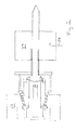
- an electron gun arrangement comprises a cathode 1 having a curved front surface 2 in front of which is located a curved control grid 3 closely spaced therefrom and conforming to the profile of the cathode front surface 2.
- An annular focus electrode 4 is located in front of the cathode 2.
- a heater 5 is located behind the cathode 1 and during use causes the temperature of the cathode 1 to be raised to a temperature sufficiently high for electrons to be emitted from the front surface 2.
- the cathode 1 is supported by a cylindrical cathode support 6.
- the control grid 3 and focus electrode 4 are mounted on a common grid mount 7 which is annular and arranged about the cathode 1.
- the grid mount 7 is supported by a grid mount support 8 which is also cylindrical and coaxially surrounds the cathode support 6.
- the electron gun assembly is contained within a vacuum envelope which is partially defined by an end portion 9 which is mounted on a Kovar support 10 to give a vacuum seal therewith, the Kovar support 10 providing a mount for the cylindrical cathode support 6.
- the Kovar support 10 is in turn brazed to a conical ceramic member 11, the other end of which is brazed to a electrode mount 12 on which the electrode support 8 is fixed at its end which terminates in a flange.
- the mount 12 is of Kovar and forms part of the vacuum envelope where it is sealed to the adjacent ceramic member 11.
- a flexible member 13 of copper is arranged circumferentially about the electrode mount 12. It comprises an annular ring having a portion 14 of reduced width which projects rearwardly in an axial direction and which is sealed by a vacuum joint to the electrode mount 12.
- a groove 15 surrounds the base of the projection 14 so as to give a relatively long wall of reduced thickness to provide improved flexibility compared to what would be the case if the groove 15 were omitted.
- the copper flexible member 13 is further joined by a vacuum tight seal to a ceramic cylinder 16 by means of metal flares 17 and 18, a ceramic balance ring 19 being located between the flexible member 13 and the metal flare 18.
- the ceramic cylinder 16 is sealed at its other end via a flare arrangement 20 to an end plate 21 which also acts as an anode for the electron gun.
- the electron gun arrangement is in this embodiment adapted for use in an IOT and the conical ceramic cylinder 11 forms a microwave window via which high frequency input signals are applied to the space between the cathode 1 and grid 3 to cause modulation of the electron beam generated along longitudinal axis X-X.
- Figure 2 schematically illustrates the electron gun arrangement of Figure 1 incorporated in an IOT and shows the input cavity 22 and an output cavity 23 via which an amplified high frequency signal is extracted via a coupling loop arrangement shown at 24.
- the electron beam tube becomes hot and various parts of the tube expand to a greater or lesser extent depending on their coefficient of thermal expansion.
- the cylindrical grid support 8 is mounted on a support 12 of Kovar and the cathode support 6 is mounted on Kovar support 10.
- Kovar has a very low coefficient thermal expansion
- the spacing between the front surface 2 of the cathode 1 and the control grid 3 remains substantially fixed.
- the flexible mount 13 of copper, together with to some extent the metal flares 17, 18, and 20 provide the compliance in the vacuum envelope structure to accommodate the changes in dimensions in the structure as a whole.
Landscapes
- Microwave Tubes (AREA)
- Electrodes For Cathode-Ray Tubes (AREA)
Applications Claiming Priority (2)
| Application Number | Priority Date | Filing Date | Title |
|---|---|---|---|
| GB9809821A GB2337151B (en) | 1998-05-09 | 1998-05-09 | Electron gun arrangements |
| GB9809821 | 1998-05-09 |
Publications (2)
| Publication Number | Publication Date |
|---|---|
| EP0957504A2 true EP0957504A2 (de) | 1999-11-17 |
| EP0957504A3 EP0957504A3 (de) | 2001-12-05 |
Family
ID=10831654
Family Applications (1)
| Application Number | Title | Priority Date | Filing Date |
|---|---|---|---|
| EP99303554A Withdrawn EP0957504A3 (de) | 1998-05-09 | 1999-05-06 | Elektronenstrahlerzeugungsvorrichtungen |
Country Status (5)
| Country | Link |
|---|---|
| US (1) | US6614158B1 (de) |
| EP (1) | EP0957504A3 (de) |
| CN (1) | CN1188890C (de) |
| CA (1) | CA2271250A1 (de) |
| GB (1) | GB2337151B (de) |
Cited By (1)
| Publication number | Priority date | Publication date | Assignee | Title |
|---|---|---|---|---|
| WO2002086936A1 (en) * | 2001-04-23 | 2002-10-31 | Litton Systems, Inc. | Linear beam sevices with a gridded electron gun |
Families Citing this family (6)
| Publication number | Priority date | Publication date | Assignee | Title |
|---|---|---|---|---|
| GB2422050A (en) * | 2005-05-18 | 2006-07-12 | E2V Tech | Inductive output tube |
| US7964502B2 (en) | 2008-11-25 | 2011-06-21 | Freescale Semiconductor, Inc. | Multilayered through via |
| CN103376343B (zh) * | 2012-04-28 | 2015-11-04 | 中国科学院电子学研究所 | 一种用于强流电子注分析仪的可移动极间距电子枪系统 |
| CN107120435B (zh) * | 2017-03-28 | 2018-09-21 | 嘉兴日雅光电有限公司 | 一种电子枪维护用真空密封装置 |
| FR3098640B1 (fr) * | 2019-07-08 | 2021-11-26 | Thales Sa | Cathode annulaire pour tube electronique |
| CN114284121B (zh) * | 2021-12-24 | 2023-09-19 | 中国科学院空天信息创新研究院 | 用于行波管的电子枪及其制备方法 |
Family Cites Families (15)
| Publication number | Priority date | Publication date | Assignee | Title |
|---|---|---|---|---|
| US3737711A (en) * | 1968-11-21 | 1973-06-05 | Varian Associates | Electron tube having an improved filamentary cathode and support therefor and method of making same |
| US3983446A (en) * | 1971-07-06 | 1976-09-28 | Varian Associates | Gridded convergent flow electron gun for linear beam tubes |
| US3863163A (en) * | 1973-04-20 | 1975-01-28 | Sherman R Farrell | Broad beam electron gun |
| FR2251096B1 (de) * | 1973-11-13 | 1977-08-19 | Thomson Csf | |
| US3963955A (en) * | 1974-04-15 | 1976-06-15 | Varian Associates | Means and method for suppressing oscillations in electron guns |
| EP0025221B1 (de) * | 1979-09-05 | 1983-06-29 | Kabushiki Kaisha Toshiba | Flache Anzeigevorrichtung |
| US4480210A (en) * | 1982-05-12 | 1984-10-30 | Varian Associates, Inc. | Gridded electron power tube |
| US4559468A (en) * | 1982-06-25 | 1985-12-17 | Raytheon Company | Cathode ray tube gun support |
| DE4016556A1 (de) * | 1990-05-23 | 1991-11-28 | Zeiss Carl Fa | Hochspannungsdurchfuehrung fuer korpuskularstrahlgeraete |
| GB2287579B (en) * | 1994-03-16 | 1997-05-07 | Eev Ltd | Electron gun arrangements |
| US5623183A (en) * | 1995-03-22 | 1997-04-22 | Litton Systems, Inc. | Diverging beam electron gun for a toxic remediation device with a dome-shaped focusing electrode |
| US5969471A (en) * | 1996-02-21 | 1999-10-19 | Industrial Technology Research Institute | Grid assembly for cathode-ray tubes and method of making |
| FR2752987B1 (fr) * | 1996-09-04 | 1998-11-13 | Asulab Sa | Dispositif d'affichage electro-optique et support flexible pour de tels dispositifs servant a l'alimentation de ces dispositifs |
| US5990622A (en) * | 1998-02-02 | 1999-11-23 | Litton Systems, Inc. | Grid support structure for an electron beam device |
| US6133786A (en) * | 1998-04-03 | 2000-10-17 | Litton Systems, Inc. | Low impedance grid-anode interaction region for an inductive output amplifier |
-
1998
- 1998-05-09 GB GB9809821A patent/GB2337151B/en not_active Expired - Lifetime
-
1999
- 1999-05-06 EP EP99303554A patent/EP0957504A3/de not_active Withdrawn
- 1999-05-07 US US09/306,811 patent/US6614158B1/en not_active Expired - Fee Related
- 1999-05-07 CA CA002271250A patent/CA2271250A1/en not_active Abandoned
- 1999-05-09 CN CNB991076265A patent/CN1188890C/zh not_active Expired - Lifetime
Cited By (2)
| Publication number | Priority date | Publication date | Assignee | Title |
|---|---|---|---|---|
| WO2002086936A1 (en) * | 2001-04-23 | 2002-10-31 | Litton Systems, Inc. | Linear beam sevices with a gridded electron gun |
| US6664720B2 (en) | 2001-04-23 | 2003-12-16 | L-3 Communications Corporation | Temperature compensated gun |
Also Published As
| Publication number | Publication date |
|---|---|
| GB2337151B (en) | 2002-08-28 |
| EP0957504A3 (de) | 2001-12-05 |
| GB9809821D0 (en) | 1998-07-08 |
| CN1188890C (zh) | 2005-02-09 |
| CN1235366A (zh) | 1999-11-17 |
| US6614158B1 (en) | 2003-09-02 |
| CA2271250A1 (en) | 1999-11-09 |
| GB2337151A (en) | 1999-11-10 |
Similar Documents
| Publication | Publication Date | Title |
|---|---|---|
| US6614158B1 (en) | Electron gun arrangements having closely spaced cathode and electrode and a vacuum seal | |
| US5629582A (en) | Thermally stable electron gun arrangement with electrically non-conductive spacer members | |
| US5684364A (en) | Electron beam tube collector having ceramic shielding means | |
| EP0945891B1 (de) | Elektronenstrahlröhre | |
| GB2326272A (en) | Grids for electron beam tubes | |
| US3706002A (en) | Electron gun | |
| GB2287579A (en) | Electron gun arrangements | |
| US5821693A (en) | Electron beam tubes having a unitary envelope having stepped inner surface | |
| EP0957505A2 (de) | Elektronenkanonenvorrichtung | |
| CA2508075C (en) | Electron beam tubes | |
| GB2602129A (en) | Electron gun | |
| US4900973A (en) | Electron tube sealing structure | |
| JP2677212B2 (ja) | 直線ビームマイクロ波管の製造方法 | |
| US6664720B2 (en) | Temperature compensated gun | |
| JP2602297B2 (ja) | ジャイロトロン | |
| JPH03238734A (ja) | 中空電子ビーム放出用電子銃構体 | |
| KR19990085530A (ko) | 레이저 음극선관 | |
| JPH0451427A (ja) | マイクロ波管の電子銃構体 | |
| JPS6185754A (ja) | 電子管用電子銃 | |
| GB2152741A (en) | Producing an electron beam | |
| JPS60198035A (ja) | 電子銃構体 |
Legal Events
| Date | Code | Title | Description |
|---|---|---|---|
| PUAI | Public reference made under article 153(3) epc to a published international application that has entered the european phase |
Free format text: ORIGINAL CODE: 0009012 |
|
| AK | Designated contracting states |
Kind code of ref document: A2 Designated state(s): AT BE CH CY DE DK ES FI FR GB GR IE IT LI LU MC NL PT SE |
|
| AX | Request for extension of the european patent |
Free format text: AL;LT;LV;MK;RO;SI |
|
| PUAL | Search report despatched |
Free format text: ORIGINAL CODE: 0009013 |
|
| AK | Designated contracting states |
Kind code of ref document: A3 Designated state(s): AT BE CH CY DE DK ES FI FR GB GR IE IT LI LU MC NL PT SE |
|
| AX | Request for extension of the european patent |
Free format text: AL;LT;LV;MK;RO;SI |
|
| RIC1 | Information provided on ipc code assigned before grant |
Free format text: 7H 01J 21/10 A, 7H 01J 19/42 B, 7H 01J 23/065 B |
|
| 17P | Request for examination filed |
Effective date: 20020531 |
|
| AKX | Designation fees paid |
Free format text: AT BE CH CY DE DK ES FI FR GB GR IE IT LI LU MC NL PT SE |
|
| RAP1 | Party data changed (applicant data changed or rights of an application transferred) |
Owner name: E2V TECHNOLOGIES (UK) LIMITED |
|
| 17Q | First examination report despatched |
Effective date: 20050413 |
|
| STAA | Information on the status of an ep patent application or granted ep patent |
Free format text: STATUS: THE APPLICATION IS DEEMED TO BE WITHDRAWN |
|
| 18D | Application deemed to be withdrawn |
Effective date: 20080718 |