EP0957258B1 - Air vent construction of subtank in engine - Google Patents
Air vent construction of subtank in engine Download PDFInfo
- Publication number
- EP0957258B1 EP0957258B1 EP97949159A EP97949159A EP0957258B1 EP 0957258 B1 EP0957258 B1 EP 0957258B1 EP 97949159 A EP97949159 A EP 97949159A EP 97949159 A EP97949159 A EP 97949159A EP 0957258 B1 EP0957258 B1 EP 0957258B1
- Authority
- EP
- European Patent Office
- Prior art keywords
- air vent
- fuel
- subsidiary tank
- intake
- engine
- Prior art date
- Legal status (The legal status is an assumption and is not a legal conclusion. Google has not performed a legal analysis and makes no representation as to the accuracy of the status listed.)
- Expired - Lifetime
Links
- 238000010276 construction Methods 0.000 title 1
- 239000000446 fuel Substances 0.000 claims abstract description 88
- 230000003584 silencer Effects 0.000 claims abstract description 16
- 238000002347 injection Methods 0.000 claims abstract description 10
- 239000007924 injection Substances 0.000 claims abstract description 10
- 238000011144 upstream manufacturing Methods 0.000 claims description 2
- 239000002828 fuel tank Substances 0.000 abstract description 2
- 239000000725 suspension Substances 0.000 abstract 1
- 230000005484 gravity Effects 0.000 description 4
- 230000003247 decreasing effect Effects 0.000 description 2
- 239000006185 dispersion Substances 0.000 description 2
- 238000001816 cooling Methods 0.000 description 1
- 230000000694 effects Effects 0.000 description 1
- 230000013011 mating Effects 0.000 description 1
- 238000012986 modification Methods 0.000 description 1
- 230000004048 modification Effects 0.000 description 1
- 230000001105 regulatory effect Effects 0.000 description 1
- 238000009423 ventilation Methods 0.000 description 1
- XLYOFNOQVPJJNP-UHFFFAOYSA-N water Substances O XLYOFNOQVPJJNP-UHFFFAOYSA-N 0.000 description 1
Images


Classifications
-
- F—MECHANICAL ENGINEERING; LIGHTING; HEATING; WEAPONS; BLASTING
- F02—COMBUSTION ENGINES; HOT-GAS OR COMBUSTION-PRODUCT ENGINE PLANTS
- F02M—SUPPLYING COMBUSTION ENGINES IN GENERAL WITH COMBUSTIBLE MIXTURES OR CONSTITUENTS THEREOF
- F02M37/00—Apparatus or systems for feeding liquid fuel from storage containers to carburettors or fuel-injection apparatus; Arrangements for purifying liquid fuel specially adapted for, or arranged on, internal-combustion engines
- F02M37/0047—Layout or arrangement of systems for feeding fuel
- F02M37/007—Layout or arrangement of systems for feeding fuel characterised by its use in vehicles, in stationary plants or in small engines, e.g. hand held tools
-
- F—MECHANICAL ENGINEERING; LIGHTING; HEATING; WEAPONS; BLASTING
- F02—COMBUSTION ENGINES; HOT-GAS OR COMBUSTION-PRODUCT ENGINE PLANTS
- F02B—INTERNAL-COMBUSTION PISTON ENGINES; COMBUSTION ENGINES IN GENERAL
- F02B61/00—Adaptations of engines for driving vehicles or for driving propellers; Combinations of engines with gearing
- F02B61/04—Adaptations of engines for driving vehicles or for driving propellers; Combinations of engines with gearing for driving propellers
- F02B61/045—Adaptations of engines for driving vehicles or for driving propellers; Combinations of engines with gearing for driving propellers for marine engines
-
- F—MECHANICAL ENGINEERING; LIGHTING; HEATING; WEAPONS; BLASTING
- F02—COMBUSTION ENGINES; HOT-GAS OR COMBUSTION-PRODUCT ENGINE PLANTS
- F02B—INTERNAL-COMBUSTION PISTON ENGINES; COMBUSTION ENGINES IN GENERAL
- F02B75/00—Other engines
- F02B75/16—Engines characterised by number of cylinders, e.g. single-cylinder engines
- F02B75/18—Multi-cylinder engines
- F02B75/20—Multi-cylinder engines with cylinders all in one line
-
- F—MECHANICAL ENGINEERING; LIGHTING; HEATING; WEAPONS; BLASTING
- F02—COMBUSTION ENGINES; HOT-GAS OR COMBUSTION-PRODUCT ENGINE PLANTS
- F02M—SUPPLYING COMBUSTION ENGINES IN GENERAL WITH COMBUSTIBLE MIXTURES OR CONSTITUENTS THEREOF
- F02M35/00—Combustion-air cleaners, air intakes, intake silencers, or induction systems specially adapted for, or arranged on, internal-combustion engines
- F02M35/10—Air intakes; Induction systems
- F02M35/10209—Fluid connections to the air intake system; their arrangement of pipes, valves or the like
- F02M35/10222—Exhaust gas recirculation [EGR]; Positive crankcase ventilation [PCV]; Additional air admission, lubricant or fuel vapour admission
-
- F—MECHANICAL ENGINEERING; LIGHTING; HEATING; WEAPONS; BLASTING
- F02—COMBUSTION ENGINES; HOT-GAS OR COMBUSTION-PRODUCT ENGINE PLANTS
- F02M—SUPPLYING COMBUSTION ENGINES IN GENERAL WITH COMBUSTIBLE MIXTURES OR CONSTITUENTS THEREOF
- F02M35/00—Combustion-air cleaners, air intakes, intake silencers, or induction systems specially adapted for, or arranged on, internal-combustion engines
- F02M35/10—Air intakes; Induction systems
- F02M35/104—Intake manifolds
- F02M35/112—Intake manifolds for engines with cylinders all in one line
-
- F—MECHANICAL ENGINEERING; LIGHTING; HEATING; WEAPONS; BLASTING
- F02—COMBUSTION ENGINES; HOT-GAS OR COMBUSTION-PRODUCT ENGINE PLANTS
- F02M—SUPPLYING COMBUSTION ENGINES IN GENERAL WITH COMBUSTIBLE MIXTURES OR CONSTITUENTS THEREOF
- F02M35/00—Combustion-air cleaners, air intakes, intake silencers, or induction systems specially adapted for, or arranged on, internal-combustion engines
- F02M35/12—Intake silencers ; Sound modulation, transmission or amplification
-
- F—MECHANICAL ENGINEERING; LIGHTING; HEATING; WEAPONS; BLASTING
- F02—COMBUSTION ENGINES; HOT-GAS OR COMBUSTION-PRODUCT ENGINE PLANTS
- F02M—SUPPLYING COMBUSTION ENGINES IN GENERAL WITH COMBUSTIBLE MIXTURES OR CONSTITUENTS THEREOF
- F02M35/00—Combustion-air cleaners, air intakes, intake silencers, or induction systems specially adapted for, or arranged on, internal-combustion engines
- F02M35/16—Combustion-air cleaners, air intakes, intake silencers, or induction systems specially adapted for, or arranged on, internal-combustion engines characterised by use in vehicles
- F02M35/165—Marine vessels; Ships; Boats
- F02M35/167—Marine vessels; Ships; Boats having outboard engines; Jet-skis
-
- F—MECHANICAL ENGINEERING; LIGHTING; HEATING; WEAPONS; BLASTING
- F02—COMBUSTION ENGINES; HOT-GAS OR COMBUSTION-PRODUCT ENGINE PLANTS
- F02M—SUPPLYING COMBUSTION ENGINES IN GENERAL WITH COMBUSTIBLE MIXTURES OR CONSTITUENTS THEREOF
- F02M37/00—Apparatus or systems for feeding liquid fuel from storage containers to carburettors or fuel-injection apparatus; Arrangements for purifying liquid fuel specially adapted for, or arranged on, internal-combustion engines
- F02M37/0076—Details of the fuel feeding system related to the fuel tank
- F02M37/0088—Multiple separate fuel tanks or tanks being at least partially partitioned
-
- F—MECHANICAL ENGINEERING; LIGHTING; HEATING; WEAPONS; BLASTING
- F02—COMBUSTION ENGINES; HOT-GAS OR COMBUSTION-PRODUCT ENGINE PLANTS
- F02B—INTERNAL-COMBUSTION PISTON ENGINES; COMBUSTION ENGINES IN GENERAL
- F02B75/00—Other engines
- F02B75/02—Engines characterised by their cycles, e.g. six-stroke
- F02B2075/022—Engines characterised by their cycles, e.g. six-stroke having less than six strokes per cycle
- F02B2075/027—Engines characterised by their cycles, e.g. six-stroke having less than six strokes per cycle four
-
- F—MECHANICAL ENGINEERING; LIGHTING; HEATING; WEAPONS; BLASTING
- F02—COMBUSTION ENGINES; HOT-GAS OR COMBUSTION-PRODUCT ENGINE PLANTS
- F02B—INTERNAL-COMBUSTION PISTON ENGINES; COMBUSTION ENGINES IN GENERAL
- F02B75/00—Other engines
- F02B75/16—Engines characterised by number of cylinders, e.g. single-cylinder engines
- F02B75/18—Multi-cylinder engines
- F02B2075/1804—Number of cylinders
- F02B2075/1816—Number of cylinders four
-
- F—MECHANICAL ENGINEERING; LIGHTING; HEATING; WEAPONS; BLASTING
- F02—COMBUSTION ENGINES; HOT-GAS OR COMBUSTION-PRODUCT ENGINE PLANTS
- F02B—INTERNAL-COMBUSTION PISTON ENGINES; COMBUSTION ENGINES IN GENERAL
- F02B2275/00—Other engines, components or details, not provided for in other groups of this subclass
- F02B2275/20—SOHC [Single overhead camshaft]
-
- F—MECHANICAL ENGINEERING; LIGHTING; HEATING; WEAPONS; BLASTING
- F02—COMBUSTION ENGINES; HOT-GAS OR COMBUSTION-PRODUCT ENGINE PLANTS
- F02M—SUPPLYING COMBUSTION ENGINES IN GENERAL WITH COMBUSTIBLE MIXTURES OR CONSTITUENTS THEREOF
- F02M37/00—Apparatus or systems for feeding liquid fuel from storage containers to carburettors or fuel-injection apparatus; Arrangements for purifying liquid fuel specially adapted for, or arranged on, internal-combustion engines
- F02M37/0011—Constructional details; Manufacturing or assembly of elements of fuel systems; Materials therefor
- F02M37/0023—Valves in the fuel supply and return system
-
- F—MECHANICAL ENGINEERING; LIGHTING; HEATING; WEAPONS; BLASTING
- F02—COMBUSTION ENGINES; HOT-GAS OR COMBUSTION-PRODUCT ENGINE PLANTS
- F02M—SUPPLYING COMBUSTION ENGINES IN GENERAL WITH COMBUSTIBLE MIXTURES OR CONSTITUENTS THEREOF
- F02M37/00—Apparatus or systems for feeding liquid fuel from storage containers to carburettors or fuel-injection apparatus; Arrangements for purifying liquid fuel specially adapted for, or arranged on, internal-combustion engines
- F02M37/0047—Layout or arrangement of systems for feeding fuel
Definitions
- the present invention relates to an air vent structure in a subsidiary tank in an engine comprising a subsidiary tank as set forth in the entrance portion of claim 1 and to a subsidiary tank in an outboard engine system using said air vent structure.
- US-A-4,809,666 on which the entrance part of claim 1 is based discloses a subsidiary tank comprising a single air vent pipe.
- a similar engine is known from JP-A1-3-64658, in which an upper space in a subsidiary tank for temporarily storing fuel to be supplied to a fuel injection valve is connected to a portion near a throttle valve through a single air vent pipe.
- the pair of air vent passages are defined in an upper portion of the subsidiary tank to open at one end into an upper space in the subsidiary tank and to be connected at the other end to a pair of the air vent pipes, and disposed to cross each other at intermediate portions thereof. Therefore, even if the engine falls down sideways, the fuel is prevented from flowing out of the subsidiary tank due to the gravity, and moreover, the fuel in the subsidiary thank is prevented from being forced out into an intake system due to the internal pressure.
- an outboard engine system O includes a mount case 2 coupled to an upper portion of an extension case 1.
- a water-cooled serial 4-cylinder and 4-cycle engine E is supported on an upper surface of the mount case 2 with a crankshaft 15 disposed vertically.
- An under-case 3 having an upper surface opened is coupled to the mount case 2, and an engine cover 4 is detachably mounted on an upper portion of the under-case 3.
- An under-cover 5 is mounted between a lower edge of the under-case 3 and an edge of the extension case 1 near its upper end so as to cover an outside of the mount case 2.
- the engine E includes a cylinder block 6, a crankcase 7, a cylinder head 8, a head cover 9, a lower belt cover 10 and an upper belt cover 11. Lower surfaces of the cylinder block 6 and the crankcase 7 are supported on the upper surface of the mount case 2. Pistons 13 are slidably received in four cylinders 12 defined in the cylinder block 6 and are connected to the crankshaft 15 disposed vertically, through connecting rods 14.
- a driving shaft 17 connected to a lower end of the crankshaft 15 along with a flywheel 16 extends downwards within the extension case 1 and is connected at its lower end to a propeller shaft 21 having a propeller 20 at its rear end, through a bevel gear mechanism 19 provided within a gear case 18.
- a shift rod 22 is connected at its lower end to a front portion of the bevel gear mechanism 19 to change over the direction of rotation of the propeller shaft 21.
- a swivel shaft 25 is fixed between an upper mount 23 provided on the mount case 2 and a lower mount 24 provided on the extension case 1.
- a swivel case 26 for rotatably supporting the swivel shaft 25 is vertically swingably carried on a stern bracket 27 mounted at a stern S through a tilting shaft 28.
- An oil pan 29 and an exhaust pipe 30 are coupled to a lower surface of the mount case 2.
- An exhaust gas discharged from the exhaust pipe 30 into a space within the extension case 1 is discharged through a space within the gear case 18 and the inside of the a boss portion of the propeller 20 into the water.
- the engine E accommodated in an engine room 36 defined by the under-case 3 and the engine cover 4 includes two secondary balancer shafts 37 and 38 disposed in parallel to the crankshaft 15, and a single cam shaft 39.
- the secondary balancer shafts 37 and 38 are supported in the cylinder block 6 at locations nearer the cylinder head 8 than the crankshaft 15, and the cam shaft 39 is supported on mating faces of the cylinder head 8 and the head cover 9.
- a pulley assembly 44 is fixed to an upper end of the crankshaft 15 and comprised of a cam shaft drive pulley 40, a secondary balancer shaft drive pulley 41, a generator drive pulley 42 and a cooling fan 43 which are formed integrally with one another.
- a cam shaft follower pulley 45 fixed to an upper end of the cam shaft 39 and the cam shaft drive pulley 40 are connected to each other by an endless belt 46.
- the diameter of the cam shaft drive pulley 40 is set at one half of the diameter of the cam shaft follower pulley 45, so that the cam shaft 39 is rotated at a speed which is one half of the speed of the crankshaft 15.
- a tension pulley 49 mounted at one end of an arm 48 pivotally supported by a pin 47 is urged against an outer surface of the endless belt 46 by the resilient force of a spring 50, thereby providing a predetermined tension to the endless belt 46.
- a pair of secondary balancer shaft follower pulleys 52 and 53 are fixed respectively to an intermediate shaft 51 mounted in the vicinity of one of the secondary balancer shaft 37 and to the other secondary balancer shaft 38.
- the secondary balancer shaft follower pulleys 52 and 53 and the secondary balancer shaft drive pulley 41 are connected to each other by the endless belt 54.
- a tension pulley 57 is mounted at one end of an arm 56 pivotally supported by a pin 55 and urged against an outer surface of the endless belt 54 by the resilient force of a spring 58, thereby providing a predetermined tension to the endless belt 54.
- An intermediate shaft 52 and the one secondary balancer shaft 37 are interconnected by a pair of gears (not shown) having the same diameter, and the diameter of the secondary balancer shaft drive pulley 41 is set at two times the diameter of the secondary balancer shaft follower pulleys 52 and 53. Therefore, the pair of secondary balancer shafts 37 and 38 are rotated in opposite directions at a speed two times that of the crankshaft 15.
- a generator 62 is supported by two bolts 61, 61 on a bracket 60 which is fixed to an upper surface of the crankcase 7 by two bolts 59, 59.
- a generator follower pulley 64 fixed to a rotary shaft 63 of the generator 62 and the generator drive pulley 42 are interconnected by the endless belt 65, and the generator 62 is driven by the crankshaft 15. Since the generator 62 is mounted separately from the engine E in the above manner, the general-purpose generator 62 can be used, which is convenient for the cost and moreover, the capacity of the generator 62 can easily be increased, as compared with the case where the generator is incorporated into the flywheel mounted on the crankshaft 15 .
- An engine hanger 66 engaged by a hook of a chain block or a crane in hanging down the outboard engine system O is fixed by two bolts 67, 67 between the cam shaft 39 and the other secondary balancer shaft 38.
- the engine hanger 66 is positioned slightly at the rear of the position of the gravity center of the outboard engine system O, and it is taken into consideration that the outboard engine system 0 hung down by the engine hanger 66 can easily be mounted at and removed from the stern S as a forward-leaned attitude in which the lower end of the outboard engine system has leaped up slightly rearwards.
- the lower belt cover 10 has an opening 10 1 surrounding the periphery of the generator 62, and a plurality of slits 10 2 in its bottom wall on the right of the crankshaft 15, so that air is introduced into the belt chamber 68 through the opening 10 1 and the slits 10 2 .
- An upper end of the engine hanger 66 protrudes upwards through the upper belt cover 11.
- a pair of left and right slit-shaped air intake bores 4 1 , 4 1 are defined in a rear surface of an upper portion of the engine cover 4, and a guide plate 75 extending forwards from lower edges of the air intake bores 4 1 , 4 1 is fixed to an inner surface of the engine cover 4. Therefore , air drawn from the air intake bores 4 1 , 4 1 flows forwards through a space defined between an upper wall of the engine cover 4 and the guide plate 75 to enter the engine room 36 from a front edge of the guide plate 75.
- a ventilating duct 75 1 (see Fig.4) is formed in a right side of the guide plate 75, so that its lower end communicates with an opening 11 1 defined in a right side of the upper belt cover 11 and its upper end communicates with an opening 4 2 defined in a right side of the upper portion of the engine cover 4.
- the ventilating duct 75 1 permits the belt chamber 68 surrounded by the lower and upper belt covers 10 and 11 to be put into communication with the open air, thereby performing the ventilation.
- An intake silencer 76 is fixed to a front surface of the crankcase 7 by three bolts 77.
- the intake silencer 76 comprises a box-shaped body portion 78, and a duct portion 79 coupled to a left side of the body portion 78.
- the duct portion 79 has an intake opening 79 1 provided downwards in its lower end, and a communication bore 79 2 provided in its upper end to communicate with an internal space in the body portion 78.
- a throttle body 80 is disposed in a right side of the body portion 78 of the intake silencer 76 and connected to the body portion 78 through a short intake duct 35 having flexibility.
- the throttle body 80 is connected and fixed to an intake manifold 85 which will be described below.
- the intake manifold 85 is disposed to extend along a right side of the engine E and is integrally provided with an elbow 81, a surge tank 82, four intake pipes 83a, 83b, 83c and 83d and a mounting flange 84.
- the elbow 81 serves to change the flow of intake air by approximately 90° from the flow along the front surface of the crankcase 7 to the flow along a right side of the crankcase 7.
- the elbow 81 may be a duct having flexibility, but is integral with the surge tank 82, the intake pipes 83a, 83b, 83c and 83d and the mounting flange 84 in order to support and fix the throttle body 80 in this embodiment.
- a connecting portion between the elbow 81 and the surge tank 82 of the intake manifold 85 has a size vertically smaller than upper and lower ends of the surge tank 82.
- the intake manifold 85 is fixed at this portion to a right sidewall of the crankcase 7 by bolts 86 1 , 86 1 ; 86 2 , 86 2 and two brackets 86 3 , 86 3 having loose bores.
- the mounting flange 84 is fixed to an intake manifold mounting surface 8 1 formed on a right side of the cylinder head 8 by a plurality of bolts 87.
- the first intake pipe 83a which is first from above extends substantially horizontally along a lower surface of the lower belt cover 10, but the second to fourth intake pipes 83b, 83c and 83d which are second, third and fourth from above are inclined upwards in a forward direction from the mounting flange 84 toward the surge tank 82.
- the inclination angle of the fourth intake pipe 83d is large; the inclination angle of the third intake pipe 83c is medium, and the inclination angle of the second intake pipe 83b is small.
- the lengths of the intake pipes 83a, 83b, 83c and 83d exert a large influence to the output from the engine E under a pulsating effect of the intake system.
- the length of the horizontal first intake pipe 83a is the shortest, and the length of the fourth intake pipe 83d having the large inclination angle is the largest.
- dispersion of the lengths of the intake pipes is compensated by offsetting the positions of connections at which upstream ends of the four intake pipes 83a, 83b, 83c and 83d are connected to the surge tank 82 with respect to the intake manifold mounting surface 8 1 of the cylinder head 8 to which the mounting flange 84 at the downstream end is fixed, as shown in Figs. 4 to 5D. More specifically, the offset amounts Da, Db, Dc and Dd of the first, second, third and fourth intake pipes 83a, 83b, 83c and 83d from the intake manifold mounting surface 8 1 are set, so that the offset amount of the intake pipe is larger, as the inclination angle of the intake pipe is smaller. i.e., a relation, Da > Db > Dc > Dd is established.
- Two low-pressure fuel pumps 88, 88 each comprising a plunger pump are mounted in parallel on a rear surface of the head cover 9, so that the fuel drawn from a fuel tank (not shown) mounted within a boat through a fuel supplying pipe L 1 is supplied by the low-pressure fuel pumps 88 , 88 through a fuel supplying pipe L 2 into a subsidiary tank 89 mounted on a right side of the cylinder block 6.
- a pump driving rocker arm 103 is coaxially supported on an intake rocker arm shaft 102 supporting an intake rocker arm 101 thereon, so that one end of the pump driving rocker arm 103 abuts against a pump cam 104 provided on the cam shaft 39, while the other end abuts against a plunger 105 of the low-pressure fuel pumps 88, 88, whereby the low-pressure fuel pumps 88, 88 are driven by the cam shaft 39.
- the subsidiary tank 89 is divided into two portions: a lower-side body portion 89 1 and an upper-side cap 89 2 .
- the body portion 89 1 is fixed to two bosses formed on the fourth intake pipe 83d by bolts 106, 106 and fixed to the cylinder block 6 by two bolts 107, 107.
- a float valve 90 for regulating the fuel level and a high-pressure fuel pump 91 comprising an electromagnetic pump are accommodated within the subsidiary tank 89.
- the float valve 90 comprises an on-off valve 108 mounted at a location where the fuel supplying pipe L 2 extending from the low-pressure fuel pumps 88, 88 is connected to the subsidiary tank 89, a float 109 for moving upward and downward following the fuel level and for opening and closing the on-off valve 108, and a guide member 110 for guiding the upward and downward movements of the float 109.
- the float valve 90 is adapted to open the on-off valve 108 to introduce the fuel from the low-pressure pumps 88, 88 into the subsidiary tank 89, when the fuel level is lowered, and to close the on-off valve 108 to block the reception of the fuel from the low-pressure pumps 88, 88, when the fuel level is raised.
- the high-pressure pump 91 is disposed vertically and adapted to pump the fuel drawn from a strainer 111 disposed to extend along a bottom wall of the subsidiary tank 89, through a fuel supplying pipe L 3 into a high-pressure filter 92 which is fixed to a front portion of the subsidiary tank 89 by a band 112.
- a fuel rail 93 is fixed to the mounting flange 84 of the intake manifold 85 by a plurality of bolts 113. and four fuel injection valves 94 corresponding to the four cylinders 12 are fixed to the mounting flange 84 , so that the fuel supplied from the high-pressure filter 92 through a fuel supplying pipe L 4 to a lower end of the fuel rail 93 is distributed to the four fuel injection valves 94.
- a regulator 95 is mounted as a surplus fuel feeding-back means at an upper end of the fuel rail 93 and adapted to regulate the pressure of the fuel supplied to the fuel injection valves 94 and to return a surplus amount of the fuel to the subsidiary tank 89 through a fuel returning pipe L 5 .
- the regulator 95 and the surge tank 82 are interconnected through a negative pressure pipe L 6 .
- the subsidiary tank 89, the high-pressure fuel pump 91, the high-pressure filter 92, the fuel rail 93 and the regulator 95 form a high-pressure fuel supplying means 96.
- an upper space in the subsidiary tank 89 and the body portion 78 of the intake silencer 76 are interconnected by two air vent pipes L 7 and L 8 , as shown in Figs. 3 and 4.
- a pair of couplers 36a and 36b are mounted in a laterally isolated manner at a longitudinally central portion of an upper surface of the cap 89 2 of the subsidiary tank 89.
- One of the couplers 36a to which the air vent pipe L 8 is connected communicates with the upper space 89 3 in the subsidiary tank 89 through an L-shaped air vent passage 37a extending in the other direction in an upper wall of the cap 89 2 .
- the other coupler 36b to which the air vent pipe L 7 is connected communicates with the upper space 89 3 in the subsidiary tank 89 through an L-shaped air vent passage 37b extending in one direction in the upper wall of the cap 89 2 .
- the pair of air vent passages 37a and 37b are disposed to cross each other.
- the upper space 89 3 in the subsidiary tank 89 is connected to the intake silencer 76 through the two air vent pipes L 7 and L 8 and hence, the internal pressure in the subsidiary tank 89 is prevented from being reduced with the consumption of the fuel caused by the operation of the engine E, whereby the supplying of the fuel to the fuel injection valves 94 can be carried out without hindrance.
- the vapor of the fuel supplied to the intake silencer 76 during operation of the engine E is drawn through the intake manifold 85 into the engine E, but when the engine E is stopped, the fuel vapor is liquefied within the intake silencer 76.
- the fuel resulting from the liquefying of the fuel vapor is caught on the bottom of the intake silencer 76 having a sufficient volume and hence, there is not a possibility that such fuel may flow outside the intake system.
- the fuel caught on the bottom of the intake silencer 76 is vaporized and drawn into the engine E.
- the level of the fuel remaining within the subsidiary tank 89 is changed in a direction perpendicular to that in a usual state, but even if an opened end of either one of the air vent passages 37a and 37b. is submerged under the fuel level, the other opened end is certainly exposed above the fuel level.
- the air vent passages 37a and 37b are provided at the substantially longitudinally central portion of the subsidiary tank 89, the opened ends of the air vent passages 37a and 37b cannot be submerged under the fuel level, even if the outboard engine system O is tilted during traveling in shallows.
- the high-pressure fuel supplying means 96 is previously assembled to the intake manifold 85 to form a subassembly, whereby the number of assembling steps can be decreased to enhance the workability. More specifically, the subsidiary tank 89 having the float valve 90 and the high-pressure fuel pump 91 incorporated therein is fixed by the two bolts 106, 106 to the third and fourth intake pipes 83c and 83d of the intake manifold 85 having the fuel injection valves 94 mounted to the mounting flange 84 and further, the high-pressure filter 92 is fixed to the subsidiary tank 89 using the band 112.
- the fuel rail 93 connecting the four fuel injection valves 94 together is fixed to the mounting flange 84 of the intake manifold 85 by the bolts 113, and the regulator 95 is fixed to the fuel rail 93.
- one end of the fuel supplying pipe L 2 is connected to the float valve 90 of the subsidiary tank 89.
- the high-pressure fuel pump 91 of the subsidiary tank 89 and the high-pressure filter 92 are interconnected by the fuel supplying pipe L 3
- the high-pressure filter 92 and the lower end of the fuel rail 93 are interconnected by the fuel supplying pipe L 4 .
- the regulator 95 and the subsidiary tank 89 are interconnected by the fuel returning pipe L 5 and further, the regulator 95 and the surge tank 82 are interconnected by the negative pressure pipe L 6 .
- the assembling can be completed only by fixing the intake manifold 85 to the cylinder head 8 by the plurality of bolts 87 and fixing the subsidiary tank 89 to the cylinder block 6 by the two bolts 107, 107 and then, connecting the other end of the fuel supplying pipe L 2 to the low-pressure fuel pumps 88, 88.
- the engine E of the outboard engine system O has been illustrated in the embodiment, but the present invention is applicable to an engine used in an application other than the outboard engine system O.
Landscapes
- Engineering & Computer Science (AREA)
- Chemical & Material Sciences (AREA)
- Combustion & Propulsion (AREA)
- Mechanical Engineering (AREA)
- General Engineering & Computer Science (AREA)
- Ocean & Marine Engineering (AREA)
- Fuel-Injection Apparatus (AREA)
- Lubrication Details And Ventilation Of Internal Combustion Engines (AREA)
- Cooling, Air Intake And Gas Exhaust, And Fuel Tank Arrangements In Propulsion Units (AREA)
Abstract
Description
- The present invention relates to an air vent structure in a subsidiary tank in an engine comprising a subsidiary tank as set forth in the entrance portion of
claim 1 and to a subsidiary tank in an outboard engine system using said air vent structure. - US-A-4,809,666 on which the entrance part of
claim 1 is based discloses a subsidiary tank comprising a single air vent pipe. A similar engine is known from JP-A1-3-64658, in which an upper space in a subsidiary tank for temporarily storing fuel to be supplied to a fuel injection valve is connected to a portion near a throttle valve through a single air vent pipe. - In such an engine there is a possibility that the vapor of fuel discharged from the subsidiary tank through the air vent pipe into an intake system may be liquefied within a throttle body, when the engine is stopped. This is especially the case if the subsidiary tank is used in an outboard engine system.
- From GB-A-724652 it is per se known to use two vent pipes within an aircraft fuel system. This is due to the fact that the tank is very long and that the use of one pump only in the central position is impractical and thus two pumps should be used for the long tank of an aircraft. Thus the above-mentioned problem, especially without outboard systems, cannot be dealt with.
- Thus, it is the object of the present invention to provide an air vent structure in a subsidiary tank, wherein the treatment of the vapor of fuel discharge from the subsidiary tank into the intake system can be performed appropriately, especially with an outboard engine system.
- This object is achieved according to the present invention with the features of
claim 1. - The use of said air vent structure with an outboard engine system is set forth in
claims 2 to 4. - With the above arrangement, the pair of air vent passages are defined in an upper portion of the subsidiary tank to open at one end into an upper space in the subsidiary tank and to be connected at the other end to a pair of the air vent pipes, and disposed to cross each other at intermediate portions thereof. Therefore, even if the engine falls down sideways, the fuel is prevented from flowing out of the subsidiary tank due to the gravity, and moreover, the fuel in the subsidiary thank is prevented from being forced out into an intake system due to the internal pressure.
-
- Figs. 1 to 9B is a side view of the entire arrangement of an outboard engine system;
- Fig. 2 is an enlarged sectional view taken along a line 2-2 in Fig. 1;
- Fig. 3 is a view taken in the direction of an
arrow 3 in Fig. 2; - Fig. 4 is a view taken in the direction of an
arrow 4 in Fig. 3; - Figs. 5A to 5D are views showing shapes of intake pipes;
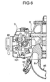
- Fig. 6 is a sectional view taken along a line 6-6 in Fig. 3;
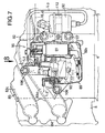
- Fig. 7 is an enlarged sectional view of an essential portion shown in Fig.3;
- Fig.8 is a view taken in the direction of an
arrow 8 in Fig.7; - Fig.9A is a sectional view taken along a
line 9A-9A in Fig.8; and - Fig.9B is a sectional view taken along a
line 9B-9B in Fig.8. - The mode for carrying the present invention will now be described by way of an embodiment shown in Figs.1 to 9B.
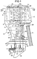
- As shown in Fig.1, an outboard engine system O includes a
mount case 2 coupled to an upper portion of anextension case 1. A water-cooled serial 4-cylinder and 4-cycle engine E is supported on an upper surface of themount case 2 with acrankshaft 15 disposed vertically. An under-case 3 having an upper surface opened is coupled to themount case 2, and anengine cover 4 is detachably mounted on an upper portion of the under-case 3. An under-cover 5 is mounted between a lower edge of the under-case 3 and an edge of theextension case 1 near its upper end so as to cover an outside of themount case 2. - The engine E includes a
cylinder block 6, acrankcase 7, acylinder head 8, ahead cover 9, alower belt cover 10 and anupper belt cover 11. Lower surfaces of thecylinder block 6 and thecrankcase 7 are supported on the upper surface of themount case 2. Pistons 13 are slidably received in fourcylinders 12 defined in thecylinder block 6 and are connected to thecrankshaft 15 disposed vertically, through connectingrods 14. - A
driving shaft 17 connected to a lower end of thecrankshaft 15 along with aflywheel 16 extends downwards within theextension case 1 and is connected at its lower end to apropeller shaft 21 having apropeller 20 at its rear end, through abevel gear mechanism 19 provided within agear case 18. Ashift rod 22 is connected at its lower end to a front portion of thebevel gear mechanism 19 to change over the direction of rotation of thepropeller shaft 21. - A
swivel shaft 25 is fixed between anupper mount 23 provided on themount case 2 and alower mount 24 provided on theextension case 1. Aswivel case 26 for rotatably supporting theswivel shaft 25 is vertically swingably carried on astern bracket 27 mounted at a stern S through a tiltingshaft 28. - An
oil pan 29 and anexhaust pipe 30 are coupled to a lower surface of themount case 2. An exhaust gas discharged from theexhaust pipe 30 into a space within theextension case 1 is discharged through a space within thegear case 18 and the inside of the a boss portion of thepropeller 20 into the water. - As can be seen from Fig. 2 , the engine E accommodated in an
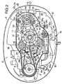
engine room 36 defined by the under-case 3 and theengine cover 4 includes twosecondary balancer shafts crankshaft 15, and asingle cam shaft 39. Thesecondary balancer shafts cylinder block 6 at locations nearer thecylinder head 8 than thecrankshaft 15, and thecam shaft 39 is supported on mating faces of thecylinder head 8 and thehead cover 9. - A
pulley assembly 44 is fixed to an upper end of thecrankshaft 15 and comprised of a camshaft drive pulley 40, a secondary balancershaft drive pulley 41, agenerator drive pulley 42 and acooling fan 43 which are formed integrally with one another. A camshaft follower pulley 45 fixed to an upper end of thecam shaft 39 and the camshaft drive pulley 40 are connected to each other by anendless belt 46. The diameter of the camshaft drive pulley 40 is set at one half of the diameter of the camshaft follower pulley 45, so that thecam shaft 39 is rotated at a speed which is one half of the speed of thecrankshaft 15. A tension pulley 49 mounted at one end of anarm 48 pivotally supported by apin 47 is urged against an outer surface of theendless belt 46 by the resilient force of aspring 50, thereby providing a predetermined tension to theendless belt 46. - A pair of secondary balancer
shaft follower pulleys intermediate shaft 51 mounted in the vicinity of one of thesecondary balancer shaft 37 and to the othersecondary balancer shaft 38. The secondary balancershaft follower pulleys shaft drive pulley 41 are connected to each other by theendless belt 54. A tension pulley 57 is mounted at one end of an arm 56 pivotally supported by a pin 55 and urged against an outer surface of theendless belt 54 by the resilient force of aspring 58, thereby providing a predetermined tension to theendless belt 54. Anintermediate shaft 52 and the onesecondary balancer shaft 37 are interconnected by a pair of gears (not shown) having the same diameter, and the diameter of the secondary balancershaft drive pulley 41 is set at two times the diameter of the secondary balancershaft follower pulleys secondary balancer shafts crankshaft 15. - A
generator 62 is supported by twobolts bracket 60 which is fixed to an upper surface of thecrankcase 7 by twobolts generator follower pulley 64 fixed to arotary shaft 63 of thegenerator 62 and thegenerator drive pulley 42 are interconnected by theendless belt 65, and thegenerator 62 is driven by thecrankshaft 15. Since thegenerator 62 is mounted separately from the engine E in the above manner, the general-purpose generator 62 can be used, which is convenient for the cost and moreover, the capacity of thegenerator 62 can easily be increased, as compared with the case where the generator is incorporated into the flywheel mounted on thecrankshaft 15 . - An
engine hanger 66 engaged by a hook of a chain block or a crane in hanging down the outboard engine system O is fixed by twobolts cam shaft 39 and the othersecondary balancer shaft 38. Theengine hanger 66 is positioned slightly at the rear of the position of the gravity center of the outboard engine system O, and it is taken into consideration that the outboard engine system 0 hung down by theengine hanger 66 can easily be mounted at and removed from the stern S as a forward-leaned attitude in which the lower end of the outboard engine system has leaped up slightly rearwards. - Three
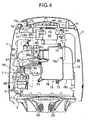
belts cam shaft 39, thesecondary balancer shafts generator 62 are accommodated in abelt chamber 68 defined by the lower and upper belt covers 10 and 11. Thelower belt cover 10 has anopening 101 surrounding the periphery of thegenerator 62, and a plurality ofslits 102 in its bottom wall on the right of thecrankshaft 15, so that air is introduced into thebelt chamber 68 through theopening 101 and theslits 102. An upper end of theengine hanger 66 protrudes upwards through theupper belt cover 11. - As can be seen from Figs. 2 to 4, a pair of left and right slit-shaped
air intake bores engine cover 4, and aguide plate 75 extending forwards from lower edges of theair intake bores engine cover 4. Therefore , air drawn from theair intake bores engine cover 4 and theguide plate 75 to enter theengine room 36 from a front edge of theguide plate 75. A ventilating duct 751 (see Fig.4) is formed in a right side of theguide plate 75, so that its lower end communicates with anopening 111 defined in a right side of theupper belt cover 11 and its upper end communicates with anopening 42 defined in a right side of the upper portion of theengine cover 4. Theventilating duct 751 permits thebelt chamber 68 surrounded by the lower and upper belt covers 10 and 11 to be put into communication with the open air, thereby performing the ventilation. - The structure of an intake system of the engine E will be described below with reference to Figs.2 to 5D.
- An
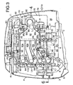
intake silencer 76 is fixed to a front surface of thecrankcase 7 by threebolts 77. Theintake silencer 76 comprises a box-shapedbody portion 78, and aduct portion 79 coupled to a left side of thebody portion 78. Theduct portion 79 has anintake opening 791 provided downwards in its lower end, and a communication bore 792 provided in its upper end to communicate with an internal space in thebody portion 78. Athrottle body 80 is disposed in a right side of thebody portion 78 of theintake silencer 76 and connected to thebody portion 78 through ashort intake duct 35 having flexibility. - The
throttle body 80 is connected and fixed to anintake manifold 85 which will be described below. Theintake manifold 85 is disposed to extend along a right side of the engine E and is integrally provided with anelbow 81, asurge tank 82, fourintake pipes flange 84. Theelbow 81 serves to change the flow of intake air by approximately 90° from the flow along the front surface of thecrankcase 7 to the flow along a right side of thecrankcase 7. Theelbow 81 may be a duct having flexibility, but is integral with thesurge tank 82, theintake pipes flange 84 in order to support and fix thethrottle body 80 in this embodiment. - A connecting portion between the
elbow 81 and thesurge tank 82 of theintake manifold 85 has a size vertically smaller than upper and lower ends of thesurge tank 82. Theintake manifold 85 is fixed at this portion to a right sidewall of thecrankcase 7 by bolts 861, 861; 862, 862 and two brackets 863, 863 having loose bores. Further, the mountingflange 84 is fixed to an intakemanifold mounting surface 81 formed on a right side of thecylinder head 8 by a plurality ofbolts 87. - As can be seen from Fig.3, the
first intake pipe 83a which is first from above extends substantially horizontally along a lower surface of thelower belt cover 10, but the second tofourth intake pipes flange 84 toward thesurge tank 82. The inclination angle of thefourth intake pipe 83d is large; the inclination angle of thethird intake pipe 83c is medium, and the inclination angle of thesecond intake pipe 83b is small. By disposing theintake pipes intake pipes cylinders 12 by the gravity, and moreover, a space can be ensured below thesurge tank 82 and thefourth intake pipe 83d, and a high-pressure fuel supplying means which will be described hereinafter can be disposed in this space. - The lengths of the
intake pipes intake pipes first intake pipe 83a is the shortest, and the length of thefourth intake pipe 83d having the large inclination angle is the largest. Therefore, in this embodiment, dispersion of the lengths of the intake pipes is compensated by offsetting the positions of connections at which upstream ends of the fourintake pipes surge tank 82 with respect to the intakemanifold mounting surface 81 of thecylinder head 8 to which the mountingflange 84 at the downstream end is fixed, as shown in Figs. 4 to 5D. More specifically, the offset amounts Da, Db, Dc and Dd of the first, second, third andfourth intake pipes manifold mounting surface 81 are set, so that the offset amount of the intake pipe is larger, as the inclination angle of the intake pipe is smaller. i.e., a relation, Da > Db > Dc > Dd is established. - As a result, the decrement in length of the
first intake pipe 83a shown in Fig.5A due to the horizontal disposition thereof is compensated by the large offset amount Da, and the increment in length of thefourth intake pipe 83d shown in Fig. 5D due to the disposition thereof in the largely inclined state is compensated by the small offset amount Dd, whereby the lengths of the fourintake pipes intake pipes - The structure of a fuel supply system in the engine E will be described below with reference to Figs.2 to 4 and 7 to 9B.
- Two low-pressure fuel pumps 88, 88 each comprising a plunger pump are mounted in parallel on a rear surface of the
head cover 9, so that the fuel drawn from a fuel tank (not shown) mounted within a boat through a fuel supplying pipe L1 is supplied by the low-pressure fuel pumps 88 , 88 through a fuel supplying pipe L2 into asubsidiary tank 89 mounted on a right side of thecylinder block 6. As can be seen from Fig. 6, a pump drivingrocker arm 103 is coaxially supported on an intakerocker arm shaft 102 supporting anintake rocker arm 101 thereon, so that one end of the pump drivingrocker arm 103 abuts against apump cam 104 provided on thecam shaft 39, while the other end abuts against aplunger 105 of the low-pressure fuel pumps 88, 88, whereby the low-pressure fuel pumps 88, 88 are driven by thecam shaft 39. - As can be seen from Figs. 3, 7 and 8, the
subsidiary tank 89 is divided into two portions: a lower-side body portion 891 and an upper-side cap 892. Thebody portion 891 is fixed to two bosses formed on thefourth intake pipe 83d bybolts cylinder block 6 by twobolts float valve 90 for regulating the fuel level and a high-pressure fuel pump 91 comprising an electromagnetic pump are accommodated within thesubsidiary tank 89. - The
float valve 90 comprises an on-offvalve 108 mounted at a location where the fuel supplying pipe L2 extending from the low-pressure fuel pumps 88, 88 is connected to thesubsidiary tank 89, afloat 109 for moving upward and downward following the fuel level and for opening and closing the on-offvalve 108, and aguide member 110 for guiding the upward and downward movements of thefloat 109. Thefloat valve 90 is adapted to open the on-offvalve 108 to introduce the fuel from the low-pressure pumps 88, 88 into thesubsidiary tank 89, when the fuel level is lowered, and to close the on-offvalve 108 to block the reception of the fuel from the low-pressure pumps 88, 88, when the fuel level is raised. The high-pressure pump 91 is disposed vertically and adapted to pump the fuel drawn from astrainer 111 disposed to extend along a bottom wall of thesubsidiary tank 89, through a fuel supplying pipe L3 into a high-pressure filter 92 which is fixed to a front portion of thesubsidiary tank 89 by aband 112. - A
fuel rail 93 is fixed to the mountingflange 84 of theintake manifold 85 by a plurality ofbolts 113. and fourfuel injection valves 94 corresponding to the fourcylinders 12 are fixed to the mountingflange 84 , so that the fuel supplied from the high-pressure filter 92 through a fuel supplying pipe L4 to a lower end of thefuel rail 93 is distributed to the fourfuel injection valves 94. Aregulator 95 is mounted as a surplus fuel feeding-back means at an upper end of thefuel rail 93 and adapted to regulate the pressure of the fuel supplied to thefuel injection valves 94 and to return a surplus amount of the fuel to thesubsidiary tank 89 through a fuel returning pipe L5. To regulate the preset pressure in theregulator 95, theregulator 95 and thesurge tank 82 are interconnected through a negative pressure pipe L6. - The
subsidiary tank 89, the high-pressure fuel pump 91, the high-pressure filter 92, thefuel rail 93 and theregulator 95 form a high-pressurefuel supplying means 96. - To prevent the fuel from flowing out of the
subsidiary tank 89 when the outboard engine system O falls down sideways, an upper space in thesubsidiary tank 89 and thebody portion 78 of theintake silencer 76 are interconnected by two air vent pipes L7 and L8, as shown in Figs. 3 and 4. As can be seen from Figs.7 to 9B, a pair ofcouplers cap 892 of thesubsidiary tank 89. One of thecouplers 36a to which the air vent pipe L8 is connected, communicates with theupper space 893 in thesubsidiary tank 89 through an L-shapedair vent passage 37a extending in the other direction in an upper wall of thecap 892. and theother coupler 36b to which the air vent pipe L7 is connected, communicates with theupper space 893 in thesubsidiary tank 89 through an L-shapedair vent passage 37b extending in one direction in the upper wall of thecap 892. Namely, the pair ofair vent passages - The
upper space 893 in thesubsidiary tank 89 is connected to theintake silencer 76 through the two air vent pipes L7 and L8 and hence, the internal pressure in thesubsidiary tank 89 is prevented from being reduced with the consumption of the fuel caused by the operation of the engine E, whereby the supplying of the fuel to thefuel injection valves 94 can be carried out without hindrance. The vapor of the fuel supplied to theintake silencer 76 during operation of the engine E is drawn through theintake manifold 85 into the engine E, but when the engine E is stopped, the fuel vapor is liquefied within theintake silencer 76. However, the fuel resulting from the liquefying of the fuel vapor is caught on the bottom of theintake silencer 76 having a sufficient volume and hence, there is not a possibility that such fuel may flow outside the intake system. When the operation of the engine E is restarted, the fuel caught on the bottom of theintake silencer 76 is vaporized and drawn into the engine E. - When the outboard engine system O removed from the boat body is stored in a sideways-fallen state, the level of the fuel remaining within the
subsidiary tank 89 is changed in a direction perpendicular to that in a usual state, but even if an opened end of either one of theair vent passages 37a and 37b. is submerged under the fuel level, the other opened end is certainly exposed above the fuel level. Therefore, even if the internal pressure in thesubsidiary tank 89 is raised due to a variation in temperature, such pressure is escaped into theintake silencer 76 through either one of theair vent passages subsidiary tank 89 cannot be forced into theintake silencer 76 through the air vent pipes L7 and L8. In addition, since the pair ofair vent passages air vent passages - Since the
air vent passages subsidiary tank 89, the opened ends of theair vent passages - When the engine E is to be assembled, the high-pressure
fuel supplying means 96 is previously assembled to theintake manifold 85 to form a subassembly, whereby the number of assembling steps can be decreased to enhance the workability. More specifically, thesubsidiary tank 89 having thefloat valve 90 and the high-pressure fuel pump 91 incorporated therein is fixed by the twobolts fourth intake pipes intake manifold 85 having thefuel injection valves 94 mounted to the mountingflange 84 and further, the high-pressure filter 92 is fixed to thesubsidiary tank 89 using theband 112. Thefuel rail 93 connecting the fourfuel injection valves 94 together is fixed to the mountingflange 84 of theintake manifold 85 by thebolts 113, and theregulator 95 is fixed to thefuel rail 93. - Then, one end of the fuel supplying pipe L2 is connected to the
float valve 90 of thesubsidiary tank 89. The high-pressure fuel pump 91 of thesubsidiary tank 89 and the high-pressure filter 92 are interconnected by the fuel supplying pipe L3, and the high-pressure filter 92 and the lower end of thefuel rail 93 are interconnected by the fuel supplying pipe L4. In addition, theregulator 95 and thesubsidiary tank 89 are interconnected by the fuel returning pipe L5 and further, theregulator 95 and thesurge tank 82 are interconnected by the negative pressure pipe L6. Thus, if the high-pressurefuel supplying means 96 and theintake manifold 85 are previously assembled as the subassembly, the assembling can be completed only by fixing theintake manifold 85 to thecylinder head 8 by the plurality ofbolts 87 and fixing thesubsidiary tank 89 to thecylinder block 6 by the twobolts intake manifold 85 to form the subassembly in the above manner, the number of assembling steps can be remarkably decreased. - Although the embodiment of the present invention has been described in detail, it will be understood that the present invention is not limited to the above-described embodiment, and various modifications in design may be made without departing the subject matter of the present invention.
- For example, the engine E of the outboard engine system O has been illustrated in the embodiment, but the present invention is applicable to an engine used in an application other than the outboard engine system O.
Claims (4)
- An air vent structure in a subsidiary tank in an engine comprising a subsidiary tank (89) for temporarily storing fuel to be supplied to a fuel injection valve (94), and an air vent pipe (L7, L8), which has one end communicating with an upper space (893) in said subsidiary tank (89) and the other end communicating with an intake silencer (76) of an intake system, the silencer being mounted to a location upstream of a throttle body (80) in a direction of flowing of intake air,
characterized in
that said air vent pipe comprises a pair of air vent pipes (L7, L8) and
that a pair of air vent passages (37a, 37b) are defined in an upper portion of said subsidiary tank (89) to open at one end into the upper space (893) in said subsidiary tank (89) and said pair of air vent passages (37a, 37b) being connected at the other end to said pair of the air vent pipes (L7, L8), said air vent passages (37a, 37b) being disposed to cross each other at intermediate portions thereof. - A subsidiary tank in an outboard engine system, the subsidiary tank having the air vent structure of claim 1,
comprising an upperside cap (892) defining said upper space (893) and comprising each said one ends of said air vent passages (37a, 37b), said one ends being positioned such that even if the outboard engine system is in a sideways-fallen state, one of said one ends is exposed above fuel level in said subsidiary tank (89). - A subsidiary tank according to claim 2,
wherein said one ends are located distantly from each other in a lateral direction of said outboard engine system. - A subsidiary tank according to claims 2 and 3,
wherein said air vent passages (37a, 37b) are provided at the substantially longitudinal central portion of the subsidiary tank (89), said one ends being positioned such that even if the outboard engine system is tilted during travelling in shallows, those cannot be submerged under the fuel level.
Applications Claiming Priority (3)
| Application Number | Priority Date | Filing Date | Title |
|---|---|---|---|
| JP34022196A JP3871751B2 (en) | 1996-12-19 | 1996-12-19 | Air vent structure of sub tank in outboard motor |
| JP34022196 | 1996-12-19 | ||
| PCT/JP1997/004699 WO1998027332A1 (en) | 1996-12-19 | 1997-12-19 | Air vent construction of subtank in engine |
Publications (3)
| Publication Number | Publication Date |
|---|---|
| EP0957258A1 EP0957258A1 (en) | 1999-11-17 |
| EP0957258A4 EP0957258A4 (en) | 2000-11-15 |
| EP0957258B1 true EP0957258B1 (en) | 2006-03-08 |
Family
ID=18334861
Family Applications (1)
| Application Number | Title | Priority Date | Filing Date |
|---|---|---|---|
| EP97949159A Expired - Lifetime EP0957258B1 (en) | 1996-12-19 | 1997-12-19 | Air vent construction of subtank in engine |
Country Status (6)
| Country | Link |
|---|---|
| US (1) | US6244251B1 (en) |
| EP (1) | EP0957258B1 (en) |
| JP (1) | JP3871751B2 (en) |
| CA (1) | CA2273255C (en) |
| DE (1) | DE69735438T2 (en) |
| WO (1) | WO1998027332A1 (en) |
Families Citing this family (5)
| Publication number | Priority date | Publication date | Assignee | Title |
|---|---|---|---|---|
| JP2001065412A (en) | 1999-08-26 | 2001-03-16 | Sanshin Ind Co Ltd | Engine |
| JP4563613B2 (en) * | 2001-05-10 | 2010-10-13 | 本田技研工業株式会社 | Fuel pump mounting structure for outboard engine |
| JP4021163B2 (en) * | 2001-07-16 | 2007-12-12 | 本田技研工業株式会社 | Sub-fuel tank / fuel pump assembly for outboard motor |
| KR100993741B1 (en) | 2004-11-25 | 2010-11-11 | 현대자동차주식회사 | Silencer |
| WO2006092972A1 (en) * | 2005-03-01 | 2006-09-08 | Honda Motor Co., Ltd. | Internal combustion engine having intake guide device |
Family Cites Families (13)
| Publication number | Priority date | Publication date | Assignee | Title |
|---|---|---|---|---|
| GB724652A (en) * | 1952-02-08 | 1955-02-23 | Nash Engineering Co | Aircraft fuel systems and booster pumps therefor |
| US4809666A (en) * | 1986-01-21 | 1989-03-07 | Outboard Marine Corporation | Fuel feed system |
| US4844043A (en) | 1988-02-22 | 1989-07-04 | Brunswick Corporation | Anti vapor lock carbureted fuel system |
| GB2217388B (en) * | 1988-04-11 | 1992-11-18 | Outboard Marine Corp | Vapour separator |
| JP2800033B2 (en) | 1989-07-31 | 1998-09-21 | スズキ株式会社 | Outboard fuel injection system |
| CA2030908A1 (en) * | 1990-03-02 | 1991-09-03 | Henry C. Billingsley | Fuel feed system |
| JPH0586997A (en) * | 1991-09-24 | 1993-04-06 | Aisan Ind Co Ltd | Fuel vaporized gas outflow preventing device |
| US5309885A (en) * | 1992-02-13 | 1994-05-10 | Outboard Marine Corporation | Marine propulsion device including a fuel injected, four-cycle internal combustion engine |
| US5438963A (en) * | 1992-09-30 | 1995-08-08 | Honda Giken Kogyo Kabushiki Kaisha | 4-cycle engine |
| US5609922A (en) | 1994-12-05 | 1997-03-11 | Mcdonald; Robert R. | Method of manufacturing molds, dies or forming tools having a cavity formed by thermal spraying |
| JPH08232765A (en) * | 1995-02-24 | 1996-09-10 | Suzuki Motor Corp | Air vent hose structure of motorcycle |
| JPH08261000A (en) * | 1995-03-27 | 1996-10-08 | Sanshin Ind Co Ltd | Fuel supply system of outboard motor |
| JP3773068B2 (en) | 1996-05-23 | 2006-05-10 | ヤマハマリン株式会社 | Fuel supply system for outboard engine |
-
1996
- 1996-12-19 JP JP34022196A patent/JP3871751B2/en not_active Expired - Fee Related
-
1997
- 1997-12-19 WO PCT/JP1997/004699 patent/WO1998027332A1/en active IP Right Grant
- 1997-12-19 US US09/308,673 patent/US6244251B1/en not_active Expired - Lifetime
- 1997-12-19 DE DE69735438T patent/DE69735438T2/en not_active Expired - Lifetime
- 1997-12-19 EP EP97949159A patent/EP0957258B1/en not_active Expired - Lifetime
- 1997-12-19 CA CA002273255A patent/CA2273255C/en not_active Expired - Fee Related
Also Published As
| Publication number | Publication date |
|---|---|
| US6244251B1 (en) | 2001-06-12 |
| EP0957258A1 (en) | 1999-11-17 |
| EP0957258A4 (en) | 2000-11-15 |
| DE69735438D1 (en) | 2006-05-04 |
| CA2273255A1 (en) | 1998-06-25 |
| JP3871751B2 (en) | 2007-01-24 |
| WO1998027332A1 (en) | 1998-06-25 |
| JPH10184478A (en) | 1998-07-14 |
| DE69735438T2 (en) | 2006-09-28 |
| CA2273255C (en) | 2004-12-14 |
Similar Documents
| Publication | Publication Date | Title |
|---|---|---|
| CA2138335C (en) | Engine and outboard engine structure | |
| JP3883239B2 (en) | Fuel supply system for outboard engine | |
| US5730632A (en) | Outboard motor | |
| US5450831A (en) | Fuel supply system for an engine | |
| CA2159046C (en) | Intake silencer in vertical type engine | |
| EP0957258B1 (en) | Air vent construction of subtank in engine | |
| US6672287B2 (en) | Fuel rail/fuel conduit connecting structure in engine of outboard engine system | |
| CA2246912C (en) | Air vent apparatus for auxillary fuel tank in power unit | |
| US6328020B1 (en) | Fuel supply construction for engines | |
| US6085713A (en) | Intake manifold for engines | |
| EP0957249B1 (en) | Outboard motor | |
| US6662786B2 (en) | Vapor separator for outboard motor | |
| US6604968B2 (en) | Intake system in V-type 4-stroke engine for outboard engine system | |
| JP3724902B2 (en) | Vertical engine intake manifold | |
| JPH10184470A (en) | Intake manifold for vertical engine | |
| JP3881736B2 (en) | Outboard motor | |
| CA2274514C (en) | Balancer shaft support structure in engine and engine hanger device in outboard engine | |
| US6616490B2 (en) | Outboard motor auxiliary fuel tank/fuel pump assembly | |
| JPH10184378A (en) | Outboard motor | |
| JPH10184798A (en) | Balancer shaft supporting structure in engine |
Legal Events
| Date | Code | Title | Description |
|---|---|---|---|
| PUAI | Public reference made under article 153(3) epc to a published international application that has entered the european phase |
Free format text: ORIGINAL CODE: 0009012 |
|
| 17P | Request for examination filed |
Effective date: 19990617 |
|
| AK | Designated contracting states |
Kind code of ref document: A1 Designated state(s): DE FR GB SE |
|
| A4 | Supplementary search report drawn up and despatched |
Effective date: 20001002 |
|
| AK | Designated contracting states |
Kind code of ref document: A4 Designated state(s): DE FR GB SE |
|
| 17Q | First examination report despatched |
Effective date: 20031202 |
|
| GRAP | Despatch of communication of intention to grant a patent |
Free format text: ORIGINAL CODE: EPIDOSNIGR1 |
|
| GRAS | Grant fee paid |
Free format text: ORIGINAL CODE: EPIDOSNIGR3 |
|
| GRAA | (expected) grant |
Free format text: ORIGINAL CODE: 0009210 |
|
| AK | Designated contracting states |
Kind code of ref document: B1 Designated state(s): DE FR GB SE |
|
| REG | Reference to a national code |
Ref country code: GB Ref legal event code: FG4D |
|
| REF | Corresponds to: |
Ref document number: 69735438 Country of ref document: DE Date of ref document: 20060504 Kind code of ref document: P |
|
| REG | Reference to a national code |
Ref country code: SE Ref legal event code: TRGR |
|
| ET | Fr: translation filed | ||
| PLBE | No opposition filed within time limit |
Free format text: ORIGINAL CODE: 0009261 |
|
| STAA | Information on the status of an ep patent application or granted ep patent |
Free format text: STATUS: NO OPPOSITION FILED WITHIN TIME LIMIT |
|
| 26N | No opposition filed |
Effective date: 20061211 |
|
| PGFP | Annual fee paid to national office [announced via postgrant information from national office to epo] |
Ref country code: SE Payment date: 20141211 Year of fee payment: 18 |
|
| REG | Reference to a national code |
Ref country code: FR Ref legal event code: PLFP Year of fee payment: 19 |
|
| PGFP | Annual fee paid to national office [announced via postgrant information from national office to epo] |
Ref country code: DE Payment date: 20151215 Year of fee payment: 19 Ref country code: GB Payment date: 20151216 Year of fee payment: 19 |
|
| PGFP | Annual fee paid to national office [announced via postgrant information from national office to epo] |
Ref country code: FR Payment date: 20151110 Year of fee payment: 19 |
|
| REG | Reference to a national code |
Ref country code: SE Ref legal event code: EUG |
|
| PG25 | Lapsed in a contracting state [announced via postgrant information from national office to epo] |
Ref country code: SE Free format text: LAPSE BECAUSE OF NON-PAYMENT OF DUE FEES Effective date: 20151220 |
|
| REG | Reference to a national code |
Ref country code: DE Ref legal event code: R119 Ref document number: 69735438 Country of ref document: DE |
|
| GBPC | Gb: european patent ceased through non-payment of renewal fee |
Effective date: 20161219 |
|
| REG | Reference to a national code |
Ref country code: FR Ref legal event code: ST Effective date: 20170831 |
|
| PG25 | Lapsed in a contracting state [announced via postgrant information from national office to epo] |
Ref country code: FR Free format text: LAPSE BECAUSE OF NON-PAYMENT OF DUE FEES Effective date: 20170102 |
|
| PG25 | Lapsed in a contracting state [announced via postgrant information from national office to epo] |
Ref country code: GB Free format text: LAPSE BECAUSE OF NON-PAYMENT OF DUE FEES Effective date: 20161219 Ref country code: DE Free format text: LAPSE BECAUSE OF NON-PAYMENT OF DUE FEES Effective date: 20170701 |