EP0956806A1 - Suction device for sucking in dirt or suction material containing dirt - Google Patents
Suction device for sucking in dirt or suction material containing dirt Download PDFInfo
- Publication number
- EP0956806A1 EP0956806A1 EP99107788A EP99107788A EP0956806A1 EP 0956806 A1 EP0956806 A1 EP 0956806A1 EP 99107788 A EP99107788 A EP 99107788A EP 99107788 A EP99107788 A EP 99107788A EP 0956806 A1 EP0956806 A1 EP 0956806A1
- Authority
- EP
- European Patent Office
- Prior art keywords
- locking
- suction
- dirt
- suction device
- bearing
- Prior art date
- Legal status (The legal status is an assumption and is not a legal conclusion. Google has not performed a legal analysis and makes no representation as to the accuracy of the status listed.)
- Granted
Links
Images


Classifications
-
- A—HUMAN NECESSITIES
- A47—FURNITURE; DOMESTIC ARTICLES OR APPLIANCES; COFFEE MILLS; SPICE MILLS; SUCTION CLEANERS IN GENERAL
- A47L—DOMESTIC WASHING OR CLEANING; SUCTION CLEANERS IN GENERAL
- A47L9/00—Details or accessories of suction cleaners, e.g. mechanical means for controlling the suction or for effecting pulsating action; Storing devices specially adapted to suction cleaners or parts thereof; Carrying-vehicles specially adapted for suction cleaners
-
- A—HUMAN NECESSITIES
- A47—FURNITURE; DOMESTIC ARTICLES OR APPLIANCES; COFFEE MILLS; SPICE MILLS; SUCTION CLEANERS IN GENERAL
- A47L—DOMESTIC WASHING OR CLEANING; SUCTION CLEANERS IN GENERAL
- A47L5/00—Structural features of suction cleaners
- A47L5/12—Structural features of suction cleaners with power-driven air-pumps or air-compressors, e.g. driven by motor vehicle engine vacuum
- A47L5/22—Structural features of suction cleaners with power-driven air-pumps or air-compressors, e.g. driven by motor vehicle engine vacuum with rotary fans
- A47L5/36—Suction cleaners with hose between nozzle and casing; Suction cleaners for fixing on staircases; Suction cleaners for carrying on the back
- A47L5/365—Suction cleaners with hose between nozzle and casing; Suction cleaners for fixing on staircases; Suction cleaners for carrying on the back of the vertical type, e.g. tank or bucket type
Definitions
- the invention relates to a suction device for sucking in dirt or the like.
- suction material for example dust air
- a dirt space for receiving the dirt or the like.
- Lower part of the device an upper part of the device arranged on the lower part, that about a laterally arranged, horizontal pivot axis pivoted on the lower part and from the top of the lower part, covering the dirt space Use position in an open position in which the Dirt room is accessible, can be swung up.
- suction devices are used, for example, in connection with a when machining a workpiece dust-generating hand machine tool used that through a hose line with the suction device is connected so that the accruing during workpiece machining Dust is extracted and collected in the dirt space of the suction device becomes.
- a suction device for dry suction material like dusty air, it can also be a suction device for act wet operation, in particular polluted water is sucked in. To remove dirt or to insert an empty dirt container, the upper part is swung up.
- the invention has for its object a suction device of the beginning to create the kind that is user-friendly and a enables easy assembly.
- the device aggregates, in particular a suction unit for sucking in the suction material and a dirt-retaining separation unit, in Area of the upper part and expediently arranged on this be so that they are locked in the open position
- Upper part are easily accessible and, if necessary, serviced can be held without the upper part being held by hand must become.
- Another advantage is that you can easily remove the top from the bottom, which is why the upper part is simply swung open into its removal position must become.
- the suction device 1 shown in the drawing is used for Suction of dirt or the like containing suction, for example Dust air.
- the suction device 1 can not only for dry suction material but also for wet suction material.
- a lateral connecting piece 2 is arranged on the suction device 1, to the outside of the suction device, only dash-dotted in Fig. 1 indicated hose line 3 can be connected.
- the other The end of the hose line 3 is, for example, with a hand tool like grinder, saw or milling machine connected, in their operation, when the respective workpiece is machined, Dust accumulates.
- a hand tool like grinder, saw or milling machine connected, in their operation, when the respective workpiece is machined, Dust accumulates.
- a handheld machine tool of course another device can also be connected.
- the suction device 1 has a lower device part 4, which has a dirty space 5 contains, in which the contained in the suction material Dirt or the like is collected.
- the dirt space 5 is up open towards.
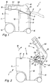
- a device upper part 6 is arranged on the lower part 4, that about a laterally arranged, horizontal pivot axis 7 is pivotally mounted on the lower part 4, so that Upper part 6 from a top 8 of the lower part 4, the dirt space 5 covering use position (Fig. 1) in an open position (Fig. 2) can be swiveled up, in which the Dirt space 5 is accessible from above, so that the dirt is removed or an empty dirt container can be used.
- a suction unit 9 in the form of a blower is included associated drive motor for sucking the suction material and a Dirt or the like restrained separation unit 10 in the form of a Filter device available.
- the equipment units 9,10 are in the embodiment on the upper part 6 and are arranged in this.
- the upper part 6 is open on its underside.
- the device units 9, 10 mentioned are only by rough outlines indicated.
- the suction unit 9 is arranged on the suction side and is located behind the separation unit when viewed in the direction of flow 10.
- the separation unit 10 is on the upper part 6 above the dirt chamber 5 arranged.
- the dirt space 5 is located in the pivot axis 7 facing away rear device area.
- the suction unit 9 is the separation unit 10 arranged upstream of the swivel axis 7 on the upper part 6 and can in the dirt chamber 5 adjacent to the pivot axis 7 out Immerse space 11 of lower part 4.
- the dirt room 5 and the space 11 just mentioned are through a partition 12 separated from each other.
- the connecting piece 2 is arranged on the lower part 4 of the device.
- the swivel axis 7 is on the same side (front) of the lower part 4 as the connecting piece 2.
- the connecting piece 2 passes through a corresponding recess in the housing of the upper part 6, which allows the pivoting of the upper part 6.
- the lower part 4 contains the suction material within the lower part in the dirt chamber 5 leading suction pipe 13, which in the area of Top 8 of the lower part 4 runs.
- the connecting piece 2 is arranged. The opposite The end of the suction pipe 13 opens into the dirt space 5.
- the suction device 1 shown is mobile and can be pushed or pulled by hand.
- a pair of front casters 14 on the underside of the suction device and a rear pair of castors 15 are present.
- the upper part 6 In its downward direction on the open upper side 8 of the lower part 4 pivoted position of use, the upper part 6, for example attached to the lower part 4 by latching.
- a locking member 16 arranged on the upper part 6 and one assigned locking recess 17 indicated on the lower part 4.
- the dirt space 5 is accessible. Furthermore, the device assemblies 9, 10 are also accessible, so that, for example, the filter device forming the separation unit 10 can be cleaned.
- the device upper part is 6 in the open position releasably lockable with the lower part 4, so that it remains in the open position. It is understood that the Locking is releasable, so that the upper part 6 in the unlocked state can be pivoted again. It is provided that the upper part 6 beyond the open position in the direction of the use position closing the lower part away into a 3 is pivotable, in which the upper part 6 can be removed from the lower part 4 (Fig. 4).
- the upper part 6 is in accordance with its arrival in the open position Fig. 2 locked automatically with the lower part 4.
- this automatic locking takes place both when swiveling up from the use position as well as when swiveling back from the removal position.
- the locking the upper part 6 with the lower part 4 in the open position Locking device has in the embodiment a locking projection 19 arranged on the upper part 6, the is directed substantially parallel to the pivot axis 7, and a contained on the lower part 4 in a locking section 21, the locking recess 19 associated locking recess 20 on.
- the locking projection 19 is in the substantially parallel to the direction of the pivot axis 7 movable by a spring force. Before the top 6 arrives in the open position, the locking projection 19 slides on Locking section 21, wherein he against the spring force Locking portion 21 is held so that when it reaches the Open position occurs in the locking recess 20.
- suction pipe 13 runs in the area of the upper side 8 of the lower part 4.
- This suction tube 13 carries the useful Embodiment, the locking portion 21 on the intake manifold 13 is arranged upwards laterally so that their Outside 25 stands tangentially from the suction pipe 13. In this way forms the circular cylindrical peripheral surface of the suction tube 13 a sliding surface arranged below the locking section 21, about the locking projection 19 when pivoting the Upper part 6 from the use position to the open position the outside 25 of the locking section 28 slides.
- the locking projection 19 also has a locking lug 26 on the locking section in the locked state 21 engages behind the locking recess 20.
- the suction pipe 13 is made of plastic.
- the locking section 21 is integrally formed on the suction pipe 13.
- the locking projection is in the embodiment 19 on the upper part 6 and the locking recess 20th arranged on the lower part 4.
- this could also be the other way round be, i.e. the locking projection could on Lower part of the device and the locking recess on the upper part of the device are located.
- the locking projection 19 instead of the locking projection 19 the locking section with the locking recess be deflectable against a spring force.
- both the locking projection and the the locking portion containing the locking recess to arrange elastically movable.
- the Locking projection 19 on a suitably made of plastic existing locking element 27 is arranged, the a locking arm forming the locking projection 19 28 and a spring arm 29 forms.
- the two arms are 28,29 V-like arranged to each other and go from one on the upper part of the device 6 fixed fastening area 30 of the locking element 27 out.
- On the fastening area 30 opposite The locking projection is located at the end of the locking arm 28 19.
- the end facing away from the fastening area 30 the spring arm 29 is supported on the upper part 6 of the device.
- Fig. 7 are the parts of the upper part 6 on which the fastening area 30 is fixed and the spring arm 29 is supported, indicated by dash-dotted lines.
- the fastening area 30 For defining the fastening area 30 this end of the locking element 27 in a Upper part 6 formed recess 31 inserted.
- the Fastening area 30 arranged on the upper part 6 of the device Retaining tabs 32 or the like attacked.
- the locking element 27 does not have to be directly on the device upper part 6 but can, how shown, on one of the equipment, conveniently on Housing of the suction unit 9, be attached.
- the locking element 27 is on the upper part 6 attached that his locking arm 28 against that of spring arm 29 exerted on the upper part 6 supporting spring arm can be pivoted in the direction of arrow 24.
- the spring arm 29 presses the locking arm 28 against arrow 24 towards the Federar m 29 away.
- the mounting arm 28 in the direction opposite arrow 24 against an end stop 33 held on the upper part of the device, which is on the side of the spring arm 29 is located.
- the locking arm 28 is on the Locking projection 19 from a stop bracket 34, which the End stop 33 forming part of the device upper part 6 engages behind.
- the locking element 27 has a plate-like overall Shape, with the spring arm 29 is formed like a tongue. The remaining area of the plate-shaped locking element 27 forms the locking arm 28.
- locking projection located on the lower part 6 of the device could be a locking element 27 corresponding locking element on the lower part of the device be arranged.
- the locking projection 19 operable to release the lock by hand.
- the locking arm 28 is pressed in the direction according to arrow 24, so that the locking projection 19 from the locking recess 20 swings out. Because of the more convenient manageability a recessed grip 35 can be provided on the locking arm 18, against which you press with a finger.
- the device upper part 6 must be removed from the lower part 4 or can be attached to this, a certain pivot position take in.
- the fixed stop 37 stands from that of the locking section 21 facing away from the peripheral side of the intake manifold 13 and is integrally molded on this.
- the pivot stop 38 has in the embodiment, a finger-like longitudinal shape on and extends inwards approximately from the area of the pivot axis 7, so that it is in the removal position of the upper part 6 from below stops at the fixed stop 27.
- the upper part 6 is in its removal position by one in the embodiment in Range raised by 90 °.
- the upper part 6 is on two in the direction the pivot axis 7 spaced apart via a respective pivot bearing device 41 with the lower part of the device 4 removably connected.
- the two swivel bearing devices 41 are located on the two front corners of the device which the front of the device (this is in the embodiment the connecting piece 2) with one device side each connected is. In the drawing is only one of the two identically designed pivot bearing devices 41 shown.
- the second swivel bearing device is located in Figures 1 to 4 congruent with the visible Swivel bearing device below the drawing level.
- the respective pivot bearing device 41 has two on the lower part 4 arranged in the swivel axis direction 7 at a distance from one another Bearing legs 42, 43 on the fork-like upward are directed and end here freely. However, it could also act as a closed arrangement.
- the Swivel bearing device 41 further includes one on the upper part 6 arranged bearing arm 44, which in the connected state engages between the two bearing legs 42, 43.
- the two Bearing legs 42, 43 have on their respective other bearing legs facing inside a circular cylindrical Pivot bearing recess 45, which is coaxial to the pivot axis line 7 are. Of the two pivot bearing recesses 45 is in 8 only the pivot bearing recess of the bearing leg 43 visible.
- Each pivot bearing recess 45 is also a axially directed pivot bearing projection 46 on the bearing arm 44 of the Device upper part 6 assigned. So that the respective pivot bearing projection 46 in the removed position of the upper part of the device 6 inserted into the relevant pivot bearing recess 45 or can be taken from this are the Pivot bearing recesses 45 arranged on their circumference Plug opening 47 accessible from the outside, the one with reference to the diameter of the respective pivot bearing recess 45 smaller width a. Furthermore, the respective one Pivot bearing projection 46 flattened on its circumference so that he in the removal position of the device upper part 6 across Swivel axis direction 7 in the direction of arrows 39 and 40 the associated plug opening 47 fits. In the embodiment the pivot bearing projection 46 has two opposite one another flattened peripheral pages 48, 49. Otherwise it is the pivot bearing projection 46 is circular cylindrical on its circumference with one of the respective pivot bearing recess 45 appropriate diameter formed.
- each Pivot bearing projection 46 into a pivot bearing recess 45 is inserted so that the device upper part 6 with twisting the pivot bearing protrusions 46 in the pivot bearing recesses 45 can pivot.
- the width a of the insertion opening 47 for stepping out the pivot bearing projection 46 concerned is too small, so that the upper part 6 is held securely on the lower part 4. Only in the removal position can the bearing arm 44 with its pulled out or inserted two pivot bearing projections 46 become.
- the arrangement could also be reversed, that the bearing arm with the at least one pivot bearing projection sits on the lower part of the device 4 and the two bearing legs with the at least one pivot bearing recess 45 on the upper part of the device 6 are arranged.
- the bearing arm 44 and the fixed stop 38 are in the embodiment formed by a one-piece plastic element, attached to the device upper part 6 in a suitable manner is.
- a handle 50 is arranged.
- the top of the top instructs the location of the handle 50 a trough 51 so that the Handle 50 is recessed and therefore not after protrudes upwards.
Abstract
Description
Die Erfindung betrifft ein Sauggerät zum Ansaugen von Schmutz od.dgl. enthaltendem Sauggut, beispielsweise Staubluft, mit einem einen Schmutzraum zur Aufnahme des Schmutzes od.dgl. enthaltenden Geräte-Unterteil, einem auf dem Unterteil angeordneten Geräte-Oberteil, das um eine seitlich angeordnete, horizontale Schwenkachse schwenkbar am Unterteil gelagert und aus einer die Oberseite des Unterteils verschließenden, den Schmutzraum überdeckenden Gebrauchsstellung in eine Offenstellung, in der der Schmutzraum zugänglich ist, hochschwenkbar ist.The invention relates to a suction device for sucking in dirt or the like. containing suction material, for example dust air, with a a dirt space for receiving the dirt or the like. containing Lower part of the device, an upper part of the device arranged on the lower part, that about a laterally arranged, horizontal pivot axis pivoted on the lower part and from the top of the lower part, covering the dirt space Use position in an open position in which the Dirt room is accessible, can be swung up.
Solche Sauggeräte werden beispielsweise in Zusammenhang mit einer beim Bearbeiten eines Werkstücks Staub erzeugenden Handwerkzeugmaschine verwendet, die über eine Schlauchleitung mit dem Sauggerät verbunden wird, so daß der bei der Werkstückbearbeitung anfallende Staub abgesaugt und im Schmutzraum des Sauggerätes gesammelt wird. Anstelle eines Sauggerätes für trockenes Sauggut wie Staubluft kann es sich jedoch auch um ein Sauggerät für den Naßbetrieb handeln, bei dem insbesondere verschmutztes Wasser angesaugt wird. Zum Entnehmen des Schmutzes oder zum Einsetzen eines leeren Schmutzbehältnisses wird das Oberteil hochgeschwenkt.Such suction devices are used, for example, in connection with a when machining a workpiece dust-generating hand machine tool used that through a hose line with the suction device is connected so that the accruing during workpiece machining Dust is extracted and collected in the dirt space of the suction device becomes. Instead of a suction device for dry suction material However, like dusty air, it can also be a suction device for act wet operation, in particular polluted water is sucked in. To remove dirt or to insert an empty dirt container, the upper part is swung up.
In Zusammenhang mit der schwenkbaren Anordnung des Oberteils liegt der Erfindung die Aufgabe zugrunde, ein Sauggerät der eingangs genannten Art zu schaffen, das benutzerfreundlich ist und eine einfache Montage ermöglicht.In connection with the swiveling arrangement of the upper part the invention has for its object a suction device of the beginning to create the kind that is user-friendly and a enables easy assembly.
Diese Aufgabe wird erfindungsgemäß dadurch gelöst, daß das Oberteil in der Offenstellung lösbar mit dem Unterteil verriegelbar und im entriegelten Zustand über die Offenstellung hinaus in Richtung von der Gebrauchsstellung weg in eine Wegnahmestellung schwenkbar ist, in der das Oberteil vom Unterteil wegnehmbar ist.This object is achieved in that the upper part releasably lockable with the lower part in the open position and in the unlocked state beyond the open position in Direction away from the use position into a removal position is pivotable, in which the upper part can be removed from the lower part.
Da das Oberteil in seiner Offenstellung verriegelt ist, hält es von selbst in dieser Stellung und muß beim Entnehmen des Schmutzes nicht mit der Hand gehalten werden. Ferner können die Geräteaggregate, insbesondere ein Saugaggregat zum Ansaugen des Saugguts und ein den Schmutz zurückhaltendes Trennaggregat, im Bereich des Oberteils und dabei zweckmäßigerweise an diesem angeordnet werden, so daß sie bei in der Offenstellung verrastetem Oberteil gut zugänglich sind und, falls erforderlich, gewartet werden können, ohne daß auch hier das Oberteil mit der Hand gehalten werden muß. Ein weiterer Vorteil besteht darin, daß man das Oberteil sehr einfach ganz vom Unterteil entfernen kann, wozu das Oberteil lediglich in seine Wegnahmestellung aufgeschwenkt werden muß. Since the upper part is locked in its open position, it holds by itself in this position and must when removing the dirt cannot be held by hand. Furthermore, the device aggregates, in particular a suction unit for sucking in the suction material and a dirt-retaining separation unit, in Area of the upper part and expediently arranged on this be so that they are locked in the open position Upper part are easily accessible and, if necessary, serviced can be held without the upper part being held by hand must become. Another advantage is that you can easily remove the top from the bottom, which is why the upper part is simply swung open into its removal position must become.
Zweckmäßige Ausgestaltungen der Erfindung sind in den Unteransprüchen angegeben.Advantageous embodiments of the invention are in the subclaims specified.
Ein Ausführungsbeispiel der Erfindung wird nun anhand der Zeichnung im einzelnen erläutert. Es zeigen:
- Fig. 1
- ein erfindungsgemäßes Sauggerät in schematischer Seitenansicht, wobei sich das Oberteil in seiner das Unterteil verschließenden Gebrauchslage befindet,
- Fig. 2
- das Sauggerät nach Fig. 1 in gleicher Darstellungsweise, wobei sich das Geräte-Oberteil in seiner hochgeschwenkten Offenstellung befindet,
- Fig. 3
- wiederum das gleiche Sauggerät in gleicher Darstellungsweise, wobei das Gerät-Oberteil noch weiter in seine Wegnahmestellung aufgeschwenkt ist,
- Fig. 4
- ebenfalls das gleiche Sauggerät in entsprechender Darstellungsweise, wobei das Oberteil vom Unterteil weggenommen ist,
- Fig. 5
- einen insbesondere die Verriegelungseinrichtung in der Wegnahmestellung zeigenden Ausschnitt gemäß Pfeil V in Fig. 3 in vergrößerter Darstellung, wobei das Oberteil und das Unterteil nur strichpunktiert angedeutet sind,
- Fig. 6
- das am Oberteil angeordnete Verriegelungselement der Anordnung nach Fig. 6 in Stirnansicht gemäß Pfeil VI in den Fig. 3 und 5,
- Fig. 7
- die Anordnung nach Fig. 5 in Draufsicht gemäß
Pfeil 7 und - Fig. 8
- den Bereich gemäß Pfeil VIII in Fig. 4 in vergrößerter Schrägansicht in Teildarstellung, so daß eine der beiden Schwenklagereinrichtungen bei vom Unterteil entferntem Oberteil erkenntlich ist.
- Fig. 1
- a suction device according to the invention in a schematic side view, wherein the upper part is in its use position closing the lower part,
- Fig. 2
- 1 in the same representation, the upper part of the device being in its swung open position,
- Fig. 3
- again the same suction device in the same representation, the upper part of the device being pivoted even further into its removal position,
- Fig. 4
- likewise the same suction device in a corresponding representation, the upper part being removed from the lower part,
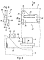
- Fig. 5
- 3 shows an enlarged section of the locking device, in particular in the removal position, according to arrow V in FIG. 3, the upper part and the lower part being indicated only by dash-dotted lines,
- Fig. 6
- 6 on the top part of the locking element of the arrangement according to FIG. 6 in an end view according to arrow VI in FIGS. 3 and 5,
- Fig. 7
- 5 in plan view according to
arrow 7 and - Fig. 8
- the area according to arrow VIII in Fig. 4 in an enlarged oblique view in partial view, so that one of the two pivot bearing devices can be seen with the upper part removed from the lower part.
Das aus der Zeichnung hervorgehende Sauggerät 1 dient zum
Ansaugen von Schmutz od.dgl. enthaltendem Sauggut, beispielsweise
Staubluft. Das Sauggerät 1 kann jedoch nicht nur für
trockenes Sauggut sondern auch für nasses Sauggut verwendet werden.The
Am Sauggerät 1 ist ein seitlicher Anschlußstutzen 2 angeordnet,
an den außen eine das Sauggerät heranführende, in Fig. 1 nur strichpunktiert
angedeutete Schlauchleitung 3 anschließbar ist. Das andere
Ende der Schlauchleitung 3 ist beispielsweise mit einer Handwerkzeugmaschine
wie Schleifgerät, Säge oder Fräsgerät verbunden,
bei deren Betrieb, wenn das jeweilige Werkstück bearbeitet wird,
Staub anfällt. Anstelle einer Handwerkzeugmaschine kann selbstverständlich
auch ein anderes Gerät angeschlossen werden.A lateral connecting
Das Sauggerät 1 weist ein Geräte-Unterteil 4 auf, das einen Schmutzraum
5 enthält, in dem der im ankommenden Sauggut enthaltene
Schmutz od.dgl. gesammelt wird. Der Schmutzraum 5 ist nach oben
hin offen. Auf dem Unterteil 4 ist ein Geräte-Oberteil 6 angeordnet,
das um eine seitlich angeordnete, horizontale Schwenkachse
7 schwenkbar am Unterteil 4 gelagert ist, so daß das
Oberteil 6 aus einer die Oberseite 8 des Unterteils 4 verschließenden,
den Schmutzraum 5 überdeckenden Gebrauchsstellung (Fig. 1) in
eine Offenstellung (Fig. 2) hochschwenkbar ist, in der der
Schmutzraum 5 von oben her zugänglich ist, so daß der Schmutz entnommen
oder ein leeres Schmutzbehältnis eingesetzt werden kann.The
Ferner sind ein Saugaggregat 9 in Gestalt eines Gebläses mit
zugehörigem Antriebsmotor zum Ansaugen des Saugguts und ein den
Schmutz od.dgl. zurückhaltendes Trennaggregat 10 in Gestalt einer
Filtereinrichtung vorhanden. Die Geräteaggregate 9,10 befinden
sich beim Ausführungsbeispiel am Oberteil 6 und sind in diesem angeordnet.
Dabei ist das Oberteil 6 an seiner Unterseite offen.
Die genannten Geräteaggregate 9,10 sind nur durch grobe Umrißlinien
angedeutet. Das Saugaggregat 9 ist saugseitig angeordnet
und befindet sich in Strömungsrichtung gesehen hinter dem Trennaggregat
10. Dabei ist das Trennaggregat 10 am Oberteil 6 oberhalb
des Schmutzraums 5 angeordnet. Das angesaugte, durch den
Anschlußstutzen 2 ankommende Sauggut gelangt in den mit dem
Anschlußstutzen 2 verbundenen Schmutzraum 5, wonach an dem Trennaggregat
10 die Schmutzpartikel aus dem Sauggut abgetrennt werden
und sich unten im Schmutzraum 5 sammeln, während die vom Schmutz
od.dgl. befreite Luft durch das Trennaggregat 10 zum Saugaggregat
9 strömt und von dort in nicht dargestellter Weise zur Geräteaußenseite
geleitet wird, wo sie ins Freie austritt.Furthermore, a
Der Schmutzraum 5 befindet sich im der Schwenkachse 7 abgewandten
hinteren Gerätebereich. Das Saugaggregat 9 ist dem Trennaggregat
10 zur Schwenkachse 7 hin vorgelagert am Oberteil 6 angeordnet
und kann in den dem Schmutzraum 5 zur Schwenkachse 7 hin benachbarten
Raum 11 des Unterteils 4 eintauchen. Der Schmutzraum 5
und der soeben genannte Raum 11 sind durch eine Trennwand 12
voneinander getrennt.The
Der Anschlußstutzen 2 ist am Geräte-Unterteil 4 angeordnet. Dabei
befindet sich die Schwenkachse 7 an der gleichen Seite (Vorderseite)
des Unterteils 4 wie der Anschlußstutzen 2. Der Anschlußstutzen
2 durchsetzt eine entsprechende Ausnehmung im Gehäuse
des Oberteils 6, die das Verschwenken des Oberteils 6 gestattet.The connecting
Das Unterteil 4 enthält ein das Sauggut innerhalb des Unterteils
in den Schmutzraum 5 führendes Saugrohr 13, das im Bereich der
Oberseite 8 des Unterteils 4 verläuft. Am äußeren, freien Ende
des Saugrohres 13 ist der Anschlußstutzen 2 angeordnet. Das entgegengesetzte
Ende des Saugrohres 13 mündet in den Schmutzraum 5.The
Das dargestellte Sauggerät 1 ist fahrbar ausgebildet und kann
dabei mit der Hand geschoben oder gezogen werden. Hierzu sind
an der Unterseite des Sauggerätes ein vorderes Fahrrollenpaar 14
und ein hinteres Fahrrollenpaar 15 vorhanden.The
In seiner nach unten auf die offene Oberseite 8 des Unterteils 4
geschwenkten Gebrauchsstellung wird das Oberteil 6 beispielsweise
durch Verrasten am Unterteil 4 befestigt. In der Zeichnung
sind ein am Oberteil 6 angeordnetes Rastglied 16 und eine diesem
zugeordnete Rastausnehmung 17 am Unterteil 4 angedeutet.In its downward direction on the open
In der in Richtung gemäß Pfeil 18 aus der Gebrauchsstellung hochgeschwenkten
Offenstellung gemäß Fig. 2 ist der Schmutzraum 5 zugänglich.
Ferner sind auch die Geräteaggregate 9,10 zugänglich,
so daß beispielsweise die das Trennaggregat 10 bildende Filtereinrichtung
gesäubert werden kann.In the direction of
Um dabei bequem hantieren zu können, ist das Geräte-Oberteil 6 in
der Offenstellung lösbar mit dem Unterteil 4 verriegelbar, so daß
es in der Offenstellung stehen bleibt. Es versteht sich, daß die
Verriegelung lösbar ist, so daß das Oberteil 6 im entriegelten Zustand
wieder verschwenkt werden kann. Dabei ist vorgesehen, daß
das Oberteil 6 über die Offenstellung hinaus in Richtung von
der das Unterteil verschließenden Gebrauchsstellung weg in eine
Wegnahmestellung gemäß Fig. 3 schwenkbar ist, in der das Oberteil
6 vom Unterteil 4 weggenommen werden kann (Fig. 4).In order to be able to handle it comfortably, the device upper part is 6 in
the open position releasably lockable with the
Zum Wegnehmen wird das Oberteil 6 einfach vom Unterteil 4 weggezogen.
Diese Wegnahme und dementsprechend das Anbringen des
Oberteils 6 am Unterteil 4 erfolgt werkzeuglos, so daß eine sehr
einfache Montage vorliegt.To remove the
Das Oberteil 6 wird bei seinem Eintreffen in die Offenstellung gemäß
Fig. 2 selbsttätig mit dem Unterteil 4 verriegelt. Beim Ausführungsbeispiel
erfolgt diese selbsttätige Verriegelung sowohl
beim Hochschwenken aus der Gebrauchsstellung als auch beim Zurückschwenken
aus der Wegnahmestellung. Prinzipiell könnte man
die Anordnung jedoch auch so treffen, daß beim Zurückschwenken
aus der Wegnahmestellung in der Offenstellung keine Verriegelung
erfolgt und das Oberteil 6 in einem Zug in die Gebrauchsstellung
auf das Unterteil 4 geschwenkt werden kann.The
Die das Oberteil 6 mit dem Unterteil 4 in der Offenstellung verriegelnde
Verriegelungseinrichtung weist beim Ausführungsbeispiel
einen am Oberteil 6 angeordneten Verriegelungsvorsprung 19, der
im wesentlichen parallel zur Schwenkachse 7 gerichtet ist, sowie
eine am Unterteil 4 in einer Verriegelungspartie 21 enthaltene,
dem Verriegeldungsvorsprung 19 zugeordnete Verriegelungsausnehmung
20 auf. Dabei ist der Verriegelungsvorsprung 19 im
wesentlichen parallel zur Richtung der Schwenkachse 7 entgegen
einer Federkraft bewegbar. Vor dem Eintreffen des Oberteils 6
in die Offenstellung gleitet der Verriegelungsvorsprung 19 auf die
Verriegelungspartie 21, wobei er durch die Federkraft gegen die
Verriegelungspartie 21 gehalten wird, so daß er beim Erreichen der
Offenstellung in die Verriegelungsausnehmung 20 eintritt.The locking the
Geht man von der Wegnahmestellung gemäß den Fig. 3 und 5 bis 7
aus und schwenkt man das Oberteil 6 entgegen Pfeil 18 zur Offenstellung
gemäß Fig. 2 hin, nähert sich der Verriegelungsvorsprung
19 an die Verriegelungspartie 21 an, wobei der Verriegelungsvorsprung
19 und die Verriegelungspartie 21 als erstes über entsprechend
genannte Schrägflächen 22,23 zur Anlage aneinander gelangen,
so daß der Verriegelungsvorsprung 19 in Richtung gemäß
Pfeil 24 (Fig. 7) entgegen der Federkraft ausgelenkt wird. Sodann
gleitet der Verriegelungsvorsprung 19 auf der Verriegelungspartie
21, bis er zur Verriegelungsausnehmung 20 gelangt, in die er unter
der Federkraft einschnappt.If one goes from the removal position according to FIGS. 3 and 5 to 7
and swings the
Für das umgekehrte Verschwenken des Oberteils 6 aus der Gebrauchsstellung
gemäß Fig. 1 in die Offenstellung nach Fig. 2 gilt
entsprechendes. Auch bei diesem Verschwenken in Richtung gemäß
Pfeil 18 gleitet der Verriegelungsvorsprung 19 unter elastischem
Ausweichen auf die Verriegelungspartie 21 und rastet dann unter
der Federkraft in die Verriegelungsausnehmung 20.For the reverse pivoting of the
Das bereits erwähnte Saugrohr 13 verläuft im Bereich der Oberseite
8 des Unterteils 4. Dieses Saugrohr 13 trägt beim zweckmäßigen
Ausführungsbeispiel die Verriegelungspartie 21, die am Saugrohr
13 nach oben hin vorstehend seitlich so angeordnet ist, daß ihre
Außenseite 25 tangential vom Saugrohr 13 hochsteht. Auf diese Weise
bildet die kreiszylindrische Umfangsfläche des Saugrohres 13 eine
unterhalb der Verriegelungspartie 21 angeordnete Aufgleitfläche,
über die der Verriegelungsvorsprung 19 beim Verschwenken des
Oberteils 6 aus der Gebrauchsstellung in die Offenstellung auf
die Außenseite 25 der Verriegelungspartie 28 gleitet.The already mentioned
Der Verriegelungsvorsprung 19 weist außerdem eine Verriegelungsnase
26 auf, die im verriegelten Zustand die Verriegelungspartie
21 neben der Verriegelungsausnehmung 20 hintergreift.The locking
Das Saugrohr 13 besteht aus Kunststoff. Die Verriegelungspartie
21 ist einstückig an das Saugrohr 13 angeformt.The
Wie bereits erwähnt, ist beim Ausführungsbeispiel der Verriegelungsvorsprung
19 am Oberteil 6 und die Verriegelungsausnehmung 20
am Unterteil 4 angeordnet. Dies könnte prinzipiell jedoch auch umgekehrt
sein, d.h. der Verriegelungsvorsprung könnte sich am
Geräte-Unterteil und die Verriegelungsausnehmung am Geräte-Oberteil
befinden. Ferner könnte anstelle des Verriegelungsvorsprungs
19 die Verriegelungspartie mit der Verriegelungsausnehmung
entgegen einer Federkraft auslenkbar sein. Des weiteren
wäre es möglich, sowohl den Verriegelungsvorsprung als auch die
die Verriegelungsausnehmung enthaltende Verriegelungspartie
elastisch bewegbar anzuordnen.As already mentioned, the locking projection is in the
Beim Ausführungsbeispiel ist des weiteren vorgesehen, daß der
Verriegelungsvorsprung 19 an einem zweckmäßigerweise aus Kunststoff
bestehenden Verriegelungselement 27 angeordnet ist, das
einen den Verriegelungsvorsprung 19 bildenden Verriegelungsarm
28 und einen Federarm 29 bildet. Die beiden Arme 28,29 sind
V-ähnlich zueinander angeordnet und gehen von einem am Geräte-Oberteil
6 festgelegten Befestigungsbereich 30 des Verriegelungselements
27 aus. Am dem Befestigungsbereich 30 entgegengesetzten
Ende des Verriegelungsarms 28 befindet sich der Verriegelungsvorsprung
19. Das dem Befestigungsbereich 30 abgewandte Ende
des Federarms 29 ist am Geräte-Oberteil 6 abgestützt. In Fig. 7
sind die Partien des Oberteils 6, an denen der Befestigungsbereich
30 festgelegt ist und sich der Federarm 29 abstützt,
strichpunktiert angedeutet. Zum Festlegen des Befestigungsbereichs
30 wird dieses Ende des Verriegelungselements 27 in eine am
Oberteil 6 ausgebildete Ausnehmung 31 gesteckt. Dabei wird der
Befestigungsbereich 30 von am Geräte-Oberteil 6 angeordneten
Haltelaschen 32 od.dgl. übergriffen. Das Verriegelungselement 27
muß nicht unmittelbar am Geräte-Oberteil 6 sondern kann, wie
dargestellt, an einem der Geräteaggregate, zweckmäßigerweise am
Gehäuse des Saugaggregats 9, befestigt sein.In the embodiment, it is further provided that the
In jedem Falle ist das Verriegelungselement 27 so am Oberteil 6
angebracht, daß sein Verriegelungsarm 28 entgegen der vom
sich am Oberteil 6 abstützenden Federarm 29 ausgeübten Federkraft
in Richtung gemäß Pfeil 24 ausgeschwenkt werden kann.In any case, the locking
Der Federarm 29 drückt den Verriegelungsarm 28 entgegen Pfeil 24
in Richtung vom Federar m 29 weg. Dabei wird der Befestigungsarm
28 in Richtung entgegen Pfeil 24 gegen einen Endanschlag 33
am Geräte-Oberteil gehalten, der sich an der Seite des Federarms
29 befindet. Vom Verriegelungsarm 28 steht an der dem
Verriegelungsvorsprung 19 ein Anschlagbügel 34 ab, der die den
Endanschlag 33 bildende Partie des Geräte-Oberteils 6 hintergreift.The
Das Verriegelungselement 27 weist insgesamt eine plattenähnliche
Gestalt auf, wobei der Federarm 29 zungenartig angeformt ist.
Der restliche Bereich des plattenförmigen Verriegelungselements
27 bildet den Verriegelungsarm 28.The locking
Würde sich entgegen dem Ausführungsbeispiel der Verriegelungsvorsprung
am Geräte-Unterteil 6 befinden, könnte ein dem Verriegelungselement
27 entsprechendes Verriegelungselement am Geräte-Unterteil
angeordnet sein.Would be contrary to the embodiment of the locking projection
located on the
Wie aus der Zeichnung ferner hervorgeht, ist der Verriegelungsvorsprung
19 zum Lösen der Verriegelung mit der Hand betätigbar.
Hierzu wird der Verriegelungsarm 28 in Richtung gemäß Pfeil 24 gedrückt,
so daß der Verriegelungsvorsprung 19 aus der Verriegelungsausnehmung
20 ausschwenkt. Der bequemeren Handbarkeit wegen
kann am Verriegelungsarm 18 eine Griffmulde 35 vorgesehen sein,
gegen die man mit einem Finger drückt.As can also be seen from the drawing, the locking
Das Geräte-Oberteil 6 muß, damit es vom Unterteil 4 weggenommen
bzw. an diesem angebracht werden kann, eine bestimmte Schwenkposition
einnehmen. Zu diesem Zwecke ist eine ein Verschwenken des
Oberteils 6 über die Wegnahmestellung hinaus verhindernde Anschlaganordnung
36 vorhanden. Diese enthält einen zweckmäßigerweise
vom Saugrohr 13 getragenen Festanschlag 37, der sich im
Schwenkweg eines am Geräte-Oberteil 6 angeordneten Schwenkanschlags
38 befindet. Der Festanschlag 37 steht von der der Verriegelungspartie
21 abgewandten Umfangsseite des Saugrohres 13 ab und
ist einstückig an diese angeformt. Der Schwenkanschlag 38 weist
beim Ausführungsbeispiel eine fingerartige Längsgestalt auf und
erstreckt sich etwa vom Bereich der Schwenkachse 7 aus nach innen,
so daß er in der Wegnahmestellung des Oberteils 6 von unten her
am Festanschlag 27 anschlägt.The device
Wie aus den Fig. 3 und 4 ersichtlich ist, ist das Oberteil 6 in
seiner Wegnahmestellung um einen beim Ausführungsbeispiel im
Bereich von 90° liegenden Winkel hochgestellt.As can be seen from FIGS. 3 and 4, the
In dieser Entnahmestellung kann das Geräte-Oberteil 6 vom Geräte-Unterteil
nach vorne hin in Richtung gemäß Pfeil 39 weggezogen
werden. Will man das Oberteil 6 wieder anbringen, wird es entgegen
Pfeil 39, in Richtung gemäß Pfeil 40, in Steckeingriff mit
dem Unterteil 4 gebracht, wonach es sich verschwenken läßt. Mit
Ausnahme in der Wegnahmestellung kann das Oberteil 6 nicht vom
Unterteil 4 entfernt werden.In this removal position, the
Beim Ausführungsbeispiel ist das Oberteil 6 an zwei in Richtung
der Schwenkachse 7 mit Abstand zueinander angeordneten Stellen
über jeweils eine Schwenklagereinrichtung 41 mit dem Geräte-Unterteil
4 entfernbar verbunden. Die beiden Schwenklagereinrichtungen
41 befinden sich an den beiden vorderen Geräteecken, an
denen die Geräte-Vorderseite (an dieser befindet sich beim Ausführungsbeispiel
der Anschlußstutzen 2) mit jeweils einer Geräteseite
verbunden ist. In der Zeichnung ist nur eine der beiden
gleich ausgebildeten Schwenklagereinrichtungen 41 dargestellt.
Die zweite Schwenklagereinrichtung befindet sich in
den Figuren 1 bis 4 deckungsgleich mit der sichtbaren
Schwenklagereinrichtung unterhalb der Zeichenebene.In the embodiment, the
Bei entsprechender axialer Abmessung könnte auch nur eine einzige Schwenklagereinrichtung genügen.With an appropriate axial dimension, only one could only swivel bearing device are sufficient.
Die jeweilige Schwenklagereinrichtung 41 weist zwei am Unterteil
4 in Schwenkachsrichtung 7 mit Abstand zueinander angeordnete
Lagerschenkel 42, 43 auf, die gabelartig nach oben
gerichtet sind und hier frei enden. Es könnte sich jedoch
auch um eine oben geschlossene Anordnung handeln. Die
Schwenklagereinrichtung 41 enthält desweiteren einen am Oberteil
6 angeordneten Lagerarm 44, der im verbundenen Zustand
zwischen die beiden Lagerschenkel 42, 43 greift. Die beiden
Lagerschenkel 42, 43 weisen an ihrer dem jeweils anderen Lagerschenkel
zugewandten Innenseite eine kreiszylindrische
Schwenklagerausnehmung 45 auf, die koaxial zur Schwenkachslinie
7 sind. Von den beiden Schwenklagerausnehmungen 45 ist in
Figur 8 nur die Schwenklagerausnehmung des Lagerschenkeis 43
sichtbar. Jeder Schwenklagerausnehmung 45 ist ein ebenfalls
axial gerichteter Schwenklagervorsprung 46 am Lagerarm 44 des
Geräte-Oberteils 6 zugeordnet. Damit der jeweilige Schwenklagervorsprung
46 in der Wegnahmestellung des Geräte-Oberteils
6 in die betreffende Schwenklagerausnehmung 45 eingesetzt beziehungsweise
aus dieser entnommen werden kann, sind die
Schwenklagerausnehmungen 45 über eine an ihrem Umfang angeordnete
Stecköffnung 47 von außen her zugänglich, die eine
mit Bezug auf den Durchmesser der jeweiligen Schwenklagerausnehmung
45 kleinere Weite a besitzt. Ferner ist der jeweilige
Schwenklagervorsprung 46 an seinem Umfang so abgeflacht, daß
er in der Wegnahmestellung des Geräte-Oberteils 6 quer zur
Schwenkachsrichtung 7 in Richtung der Pfeile 39 und 40 durch
die zugehörige Stecköffnung 47 paßt. Beim Ausführungsbeispiel
weist der Schwenklagervorsprung 46 zwei einander entgegengesetzte
abgeflachte Umfangsseiten 48, 49 auf. Ansonsten ist
der Schwenklagervorsprung 46 an seinem Umfang kreiszylindrisch
mit einem der jeweiligen Schwenklagerausnehmung 45
entsprechenden Durchmesser ausgebildet.The respective
Im verbundenen Zustand befindet sich also der Lagerarin 44
zwischen den beiden Lagerschenkeln 42, 43, wobei jeder
Schwenklagervorsprung 46 in eine Schwenklagerausnehmung 45
eingesetzt ist, so daß sich das Geräte-Oberteil 6 unter Verdrehen
der Schwenklagervorsprünge 46 in den Schwenklagerausnehmungen
45 verschwenken läßt. Mit Ausnahme in der Wegnahmestellung
ist die Weite a der Stecköffnung 47 für ein Heraustreten
des betreffenden Schwenklagervorsprungs 46 zu klein,
so daß das Oberteil 6 sicher am Unterteil 4 gehalten wird.
Erst in der Wegnahmestellung kann der Lagerarm 44 mit seinen
beiden Schwenklagervorsprüngen 46 herausgezogen bzw. eingesteckt
werden.The
Es ist ersichtlich, daß für diese Montage kein Werkzeug erforderlich ist.It can be seen that no tools are required for this assembly is.
In Abwandlung des Ausführungsbeispieles würde es genügen, nur
an einem der beiden Lagerschenkel 42, 43 eine Schwenklagerausnehmung
45 und dementsprechend am Lagerarm 44 nur einen
Schwenklagervorsprung 46 vorzusehen.In a modification of the exemplary embodiment, it would suffice, only
on one of the two bearing
Ferner könnte die Anordnung auch umgekehrt getroffen sein,
daß der Lagerarm mit dem mindestens einen Schwenklagervorsprung
am Geräte-Unterteil 4 sitzt und die beiden Lagerschenkel
mit der mindestens einen Schwenklagerausnehmung 45 am Geräte-Oberteil
6 angeordnet sind.Furthermore, the arrangement could also be reversed,
that the bearing arm with the at least one pivot bearing projection
sits on the lower part of the
Der Lagerarm 44 und der Festanschlag 38 werden beim Ausführungsbeispiel
von einem einstückigen Kunststoffelement gebildet,
das am Geräte-Oberteil 6 in geeigneter Weise befestigt
ist.The
Damit das Geräte-Oberteil 6 bei seinem Verschwenken bequem
gehalten werden kann, ist an der Oberseite des Oberteils 6
ein Handgriff 50 angeordnet. Die Oberteil-Oberseite weist an
der Stelle des Handgriffs 50 eine Mulde 51 auf, so daß der
Handgriff 50 vertieft angeordnet ist und somit nicht nach
oben hin vorsteht.So that the device
Claims (13)
Applications Claiming Priority (2)
| Application Number | Priority Date | Filing Date | Title |
|---|---|---|---|
| DE19821705A DE19821705A1 (en) | 1998-05-14 | 1998-05-14 | Suction device for sucking up dirt or the like |
| DE19821705 | 1998-05-14 |
Publications (2)
| Publication Number | Publication Date |
|---|---|
| EP0956806A1 true EP0956806A1 (en) | 1999-11-17 |
| EP0956806B1 EP0956806B1 (en) | 2004-08-04 |
Family
ID=7867804
Family Applications (1)
| Application Number | Title | Priority Date | Filing Date |
|---|---|---|---|
| EP99107788A Expired - Lifetime EP0956806B1 (en) | 1998-05-14 | 1999-04-20 | Suction device for sucking in dirt or suction material containing dirt |
Country Status (2)
| Country | Link |
|---|---|
| EP (1) | EP0956806B1 (en) |
| DE (2) | DE19821705A1 (en) |
Cited By (5)
| Publication number | Priority date | Publication date | Assignee | Title |
|---|---|---|---|---|
| EP1656871A2 (en) * | 2004-11-16 | 2006-05-17 | Samsung Gwangju Electronics Co., Ltd. | Vacuum cleaner with opening/closing means for the dust receptacle |
| CN1330273C (en) * | 2002-05-08 | 2007-08-08 | 胡佛公司 | Dust collecting system of vacuum cleaner |
| US7594945B2 (en) * | 2005-06-01 | 2009-09-29 | Samsung Gwangju Electronics Co., Ltd. | Dust receptacle fixing/separating apparatus and a cyclone dust collecting device having the same |
| CN102123641A (en) * | 2008-08-13 | 2011-07-13 | Bsh博施及西门子家用器具有限公司 | Floor care device with opening device |
| US8365350B2 (en) | 2002-11-12 | 2013-02-05 | Black & Decker Inc. | AC/DC hand portable wet/dry vacuum having improved portability and convenience |
Families Citing this family (1)
| Publication number | Priority date | Publication date | Assignee | Title |
|---|---|---|---|---|
| DE102013019224A1 (en) | 2013-11-15 | 2015-05-21 | Nilfisk-Advance A/S | Vacuum cleaner with pivoting flap |
Citations (6)
| Publication number | Priority date | Publication date | Assignee | Title |
|---|---|---|---|---|
| US3781460A (en) * | 1972-06-13 | 1973-12-25 | Whirlpool Co | Vacuum cleaner construction |
| DE2901203A1 (en) * | 1979-01-13 | 1980-07-24 | Licentia Gmbh | Vacuum cleaner lid hinge - consists of bearing pin and abutment eye with lifting device between |
| DE3122580A1 (en) * | 1981-06-06 | 1982-12-30 | Progress-Elektrogeräte Mauz & Pfeiffer GmbH & Co, 7000 Stuttgart | Vacuum cleaner |
| DE3302297A1 (en) * | 1983-01-25 | 1984-07-26 | Progress-Elektrogeräte Mauz & Pfeiffer GmbH & Co, 7000 Stuttgart | VACUUM CLEANER |
| US4463474A (en) * | 1982-06-07 | 1984-08-07 | Jacobs Paul G | Vacuum cleaner |
| DE4004177A1 (en) * | 1990-02-13 | 1991-08-14 | Miele & Cie | Wet and dry suction cleaner - has air filter and provision for two alternative sizes of dust container mountable beneath fan unit on common underframe |
-
1998
- 1998-05-14 DE DE19821705A patent/DE19821705A1/en not_active Withdrawn
-
1999
- 1999-04-20 EP EP99107788A patent/EP0956806B1/en not_active Expired - Lifetime
- 1999-04-20 DE DE59910098T patent/DE59910098D1/en not_active Expired - Lifetime
Patent Citations (6)
| Publication number | Priority date | Publication date | Assignee | Title |
|---|---|---|---|---|
| US3781460A (en) * | 1972-06-13 | 1973-12-25 | Whirlpool Co | Vacuum cleaner construction |
| DE2901203A1 (en) * | 1979-01-13 | 1980-07-24 | Licentia Gmbh | Vacuum cleaner lid hinge - consists of bearing pin and abutment eye with lifting device between |
| DE3122580A1 (en) * | 1981-06-06 | 1982-12-30 | Progress-Elektrogeräte Mauz & Pfeiffer GmbH & Co, 7000 Stuttgart | Vacuum cleaner |
| US4463474A (en) * | 1982-06-07 | 1984-08-07 | Jacobs Paul G | Vacuum cleaner |
| DE3302297A1 (en) * | 1983-01-25 | 1984-07-26 | Progress-Elektrogeräte Mauz & Pfeiffer GmbH & Co, 7000 Stuttgart | VACUUM CLEANER |
| DE4004177A1 (en) * | 1990-02-13 | 1991-08-14 | Miele & Cie | Wet and dry suction cleaner - has air filter and provision for two alternative sizes of dust container mountable beneath fan unit on common underframe |
Cited By (9)
| Publication number | Priority date | Publication date | Assignee | Title |
|---|---|---|---|---|
| CN1330273C (en) * | 2002-05-08 | 2007-08-08 | 胡佛公司 | Dust collecting system of vacuum cleaner |
| CN100544656C (en) * | 2002-05-08 | 2009-09-30 | 胡佛公司 | Equip the method for a plurality of filters for vacuum cleaner |
| US8365350B2 (en) | 2002-11-12 | 2013-02-05 | Black & Decker Inc. | AC/DC hand portable wet/dry vacuum having improved portability and convenience |
| EP1656871A2 (en) * | 2004-11-16 | 2006-05-17 | Samsung Gwangju Electronics Co., Ltd. | Vacuum cleaner with opening/closing means for the dust receptacle |
| EP1656871A3 (en) * | 2004-11-16 | 2007-05-09 | Samsung Gwangju Electronics Co., Ltd. | Vacuum cleaner with opening/closing means for the dust receptacle |
| AU2005211697C1 (en) * | 2004-11-16 | 2008-04-03 | Samsung Gwangju Electronics Co., Ltd. | Vacuum cleaner |
| US7380308B2 (en) | 2004-11-16 | 2008-06-03 | Samsung Gwangju Electronics Co., Ltd. | Vacuum cleaner |
| US7594945B2 (en) * | 2005-06-01 | 2009-09-29 | Samsung Gwangju Electronics Co., Ltd. | Dust receptacle fixing/separating apparatus and a cyclone dust collecting device having the same |
| CN102123641A (en) * | 2008-08-13 | 2011-07-13 | Bsh博施及西门子家用器具有限公司 | Floor care device with opening device |
Also Published As
| Publication number | Publication date |
|---|---|
| EP0956806B1 (en) | 2004-08-04 |
| DE19821705A1 (en) | 1999-11-18 |
| DE59910098D1 (en) | 2004-09-09 |
Similar Documents
| Publication | Publication Date | Title |
|---|---|---|
| EP0277628B1 (en) | Suction cleaning apparatus | |
| DE102004024888B4 (en) | Whirling dust collector and vacuum cleaner with such a dust collecting device | |
| DE10240632B4 (en) | Connection or connection arrangement of a vacuum cleaner and such a connection or connection arrangement exhibiting vacuum cleaner | |
| DE19522349C2 (en) | Vacuum cleaner for double operation | |
| EP1844691B1 (en) | Device for detachable fastening of a dust filter bag in a vacuum cleaner | |
| DE10124220C2 (en) | Auxiliary suction pipe arrangement for a vacuum cleaner | |
| DE19750543A1 (en) | Portable suction device | |
| EP0280831A1 (en) | Filtering apparatus, in particular for vacuum cleaner | |
| DE202011050051U1 (en) | Dust container and dust collector with the same | |
| DE10303729A1 (en) | Cyclone-type dust collecting apparatus for vacuum cleaner, has cyclone body that forms whirling air current from dust-laden air drawn into cleaner through inflow port and grill assembly to stop reverse flow of dust | |
| DE10240621A1 (en) | Vacuum cleaner with a vortex dust collector | |
| DE102016226199A1 (en) | Hand-operated cyclone vacuum cleaner and appropriate dedusting system | |
| DE102011107319B4 (en) | Flat wiper and carrier plate for it | |
| EP0956806B1 (en) | Suction device for sucking in dirt or suction material containing dirt | |
| DE202005002979U1 (en) | Suction device for filtering e.g. dust, has depositing surface horizontally located relative to vertical axis for placing upper portion removed from lower portion and including side extending section that extends behind trough | |
| DE20312836U1 (en) | Suction nozzle especially for vacuum-cleaner has pile fiber coating in front of and behind suction opening and has air inlet provided at small side of housing | |
| DE102019123150B4 (en) | Dust filter bag | |
| DE60201838T2 (en) | VACUUM CLEANER | |
| EP1247612A1 (en) | Hand-held machine tool with dust extraction | |
| EP2160942B1 (en) | Valve device for swill containers and swill bucket | |
| EP1642521B1 (en) | Dust filter box for vacuum cleaner, especially for floor vacuum cleaner and vacuum cleaner with such dust filter box | |
| DE19755997B4 (en) | Device for keeping a textile fiber transporting roller clean in a machine | |
| EP0711526B1 (en) | Connecting pipe for suction cleaner | |
| EP3189760A1 (en) | Floor cleaning machine | |
| EP1250880A1 (en) | Vacuum cleaner with swivelable mouthpiece |
Legal Events
| Date | Code | Title | Description |
|---|---|---|---|
| PUAI | Public reference made under article 153(3) epc to a published international application that has entered the european phase |
Free format text: ORIGINAL CODE: 0009012 |
|
| AK | Designated contracting states |
Kind code of ref document: A1 Designated state(s): DE FR GB IT |
|
| AX | Request for extension of the european patent |
Free format text: AL;LT;LV;MK;RO;SI |
|
| 17P | Request for examination filed |
Effective date: 19990922 |
|
| AKX | Designation fees paid |
Free format text: DE FR GB IT |
|
| RAP1 | Party data changed (applicant data changed or rights of an application transferred) |
Owner name: TTS TOOLTECHNIC SYSTEMS AG & CO. KG |
|
| 17Q | First examination report despatched |
Effective date: 20030701 |
|
| GRAP | Despatch of communication of intention to grant a patent |
Free format text: ORIGINAL CODE: EPIDOSNIGR1 |
|
| GRAS | Grant fee paid |
Free format text: ORIGINAL CODE: EPIDOSNIGR3 |
|
| GRAA | (expected) grant |
Free format text: ORIGINAL CODE: 0009210 |
|
| AK | Designated contracting states |
Kind code of ref document: B1 Designated state(s): DE FR GB IT |
|
| REG | Reference to a national code |
Ref country code: GB Ref legal event code: FG4D Free format text: NOT ENGLISH |
|
| REF | Corresponds to: |
Ref document number: 59910098 Country of ref document: DE Date of ref document: 20040909 Kind code of ref document: P |
|
| GBT | Gb: translation of ep patent filed (gb section 77(6)(a)/1977) |
Effective date: 20040909 |
|
| PLBE | No opposition filed within time limit |
Free format text: ORIGINAL CODE: 0009261 |
|
| STAA | Information on the status of an ep patent application or granted ep patent |
Free format text: STATUS: NO OPPOSITION FILED WITHIN TIME LIMIT |
|
| ET | Fr: translation filed | ||
| 26N | No opposition filed |
Effective date: 20050506 |
|
| PGFP | Annual fee paid to national office [announced via postgrant information from national office to epo] |
Ref country code: FR Payment date: 20120511 Year of fee payment: 14 |
|
| REG | Reference to a national code |
Ref country code: FR Ref legal event code: ST Effective date: 20131231 |
|
| PG25 | Lapsed in a contracting state [announced via postgrant information from national office to epo] |
Ref country code: FR Free format text: LAPSE BECAUSE OF NON-PAYMENT OF DUE FEES Effective date: 20130430 |
|
| PGFP | Annual fee paid to national office [announced via postgrant information from national office to epo] |
Ref country code: DE Payment date: 20150205 Year of fee payment: 17 |
|
| REG | Reference to a national code |
Ref country code: DE Ref legal event code: R119 Ref document number: 59910098 Country of ref document: DE |
|
| PG25 | Lapsed in a contracting state [announced via postgrant information from national office to epo] |
Ref country code: DE Free format text: LAPSE BECAUSE OF NON-PAYMENT OF DUE FEES Effective date: 20161101 |
|
| PGFP | Annual fee paid to national office [announced via postgrant information from national office to epo] |
Ref country code: IT Payment date: 20170420 Year of fee payment: 19 |
|
| PGFP | Annual fee paid to national office [announced via postgrant information from national office to epo] |
Ref country code: GB Payment date: 20180313 Year of fee payment: 20 |
|
| PG25 | Lapsed in a contracting state [announced via postgrant information from national office to epo] |
Ref country code: IT Free format text: LAPSE BECAUSE OF NON-PAYMENT OF DUE FEES Effective date: 20180420 |
|
| REG | Reference to a national code |
Ref country code: GB Ref legal event code: PE20 Expiry date: 20190419 |
|
| PG25 | Lapsed in a contracting state [announced via postgrant information from national office to epo] |
Ref country code: GB Free format text: LAPSE BECAUSE OF EXPIRATION OF PROTECTION Effective date: 20190419 |