EP0956577B1 - Latching mechanism of a switching device - Google Patents
Latching mechanism of a switching device Download PDFInfo
- Publication number
- EP0956577B1 EP0956577B1 EP98909277A EP98909277A EP0956577B1 EP 0956577 B1 EP0956577 B1 EP 0956577B1 EP 98909277 A EP98909277 A EP 98909277A EP 98909277 A EP98909277 A EP 98909277A EP 0956577 B1 EP0956577 B1 EP 0956577B1
- Authority
- EP
- European Patent Office
- Prior art keywords
- lever
- bell
- crank
- latch
- intermediate lever
- Prior art date
- Legal status (The legal status is an assumption and is not a legal conclusion. Google has not performed a legal analysis and makes no representation as to the accuracy of the status listed.)
- Expired - Lifetime
Links
Images


Classifications
-
- H—ELECTRICITY
- H01—ELECTRIC ELEMENTS
- H01H—ELECTRIC SWITCHES; RELAYS; SELECTORS; EMERGENCY PROTECTIVE DEVICES
- H01H71/00—Details of the protective switches or relays covered by groups H01H73/00 - H01H83/00
- H01H71/10—Operating or release mechanisms
- H01H71/50—Manual reset mechanisms which may be also used for manual release
- H01H71/505—Latching devices between operating and release mechanism
- H01H2071/508—Latching devices between operating and release mechanism with serial latches, e.g. primary latch latched by secondary latch for requiring a smaller trip force
Definitions
- the invention relates to a switch lock for opening and closing contacts of a switching device that a Angle lever for actuating a lock mechanism, a ratchet lever and has an intermediate lever on which the angle lever is latched in the ON position, in which the The intermediate lever is latched by the one provided for release Pawl lever exists.
- a generic switch lock is known. This is an example explained with reference to FIGS 6 and 7.
- FIG 6 shows the switch lock in the ON position, in which the long arm of the intermediate lever latched to a ratchet lever and the latching of the angle lever on the short arm of the Intermediate lever exists.
- the intermediate lever is the angle lever in the triggered Position transferred according to FIG 7.
- the angle lever grips the end of the short arm Intermediate lever and holds it against the one acting on it Return spring force in the position shown.
- the intermediate lever is released and swings in turn back to its starting position.
- DE 38 29 366 A1 there is an electrical switch with a Locking arrangement described.
- the switch points an electronic trigger circuit and also contains a reset spring in cooperation with a shift lock spring, to manually reset the switch an automatic trigger function.
- the Reset spring allows the locking arrangement of the Switch is reset manually at a minimum Path length of the switch operating handle.
- the invention has for its object a switch lock of the type mentioned above with regard to its triggering and Reset from the tripped state to the ON state to improve.
- angle lever has a protrusion that when triggered via a nose formed on the ratchet lever moved its open position. That way it can be dependent the position of the ratchet lever from the position of the bell crank to be influenced. This enables the intermediate lever during a reset to keep rotatable in the desired manner without he latched on the latch lever.
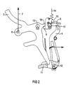
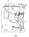
- Switch lock 1 shows a switch lock 1 of a switching device with a Bearing plate 2, an angle lever 3, an intermediate lever 4 and a ratchet lever 5, each on the bearing plate 2 are rotatably mounted.
- Switch lock 1 is located here in the ON position, in which the lower end of FIG Angle lever 3 latched on the short arm of the intermediate lever 4 is.
- With 6, the coupling point of the angle lever 3 with the Lever or lock mechanism not shown here.
- By attacking at the coupling point 6, by the Arrow 7 designated spring force is the rotation of the Angle lever 3 in the OFF position.
- In the ON position according to 1 is the intermediate lever loaded by a return spring 8 4 via the pawl lever 5 at the latching point 17 latched.
- Pawl lever 5 On the one shown here in the closed position Pawl lever 5 is a nose 9 formed on the trigger of the ratchet lever 5, a projection 10 of the angle lever 3 attacks and in this way the pawl lever 5 in his open position moves.
- the latch of the angle lever 3 takes place at the end of a ramp provided on the intermediate lever 4 11.
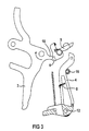
- FIG. 2 shows a schematic diagram of the lever mechanism with the three bearing points 12, 13 and 15 for the mentioned levers 3, 4 and 5.
- a compression spring 14 holds the latch lever 5 in its closed position according to FIG. 2.
- the angle lever 3 is already on the ramp 11 of the Intermediate lever 4, which is already a small Angle in relation to its starting position over the latching point 17 is turned out. At the same time, the angle lever holds 3 with its projection 10 the pawl lever 5 still in its open position.
Abstract
Description
Die Erfindung bezieht sich auf ein Schaltschloß zum Öffnen und Schließen von Kontakten eines Schaltgeräts, das einen Winkelhebel zur Betätigung einer Schloßmechanik, einen Klinkenhebel und einen Zwischenhebel aufweist, an dem der Winkelhebel in der EIN-Stellung verklinkt ist, in der zugleich die Verklinkung des Zwischenhebels durch den zur Auslösung vorgesehenen Klinkenhebel besteht.The invention relates to a switch lock for opening and closing contacts of a switching device that a Angle lever for actuating a lock mechanism, a ratchet lever and has an intermediate lever on which the angle lever is latched in the ON position, in which the The intermediate lever is latched by the one provided for release Pawl lever exists.
Ein gattungsgemäßes Schaltschloß ist bekannt. Dies wird beispielhaft anhand der FIG 6 und 7 erläutert.A generic switch lock is known. This is an example explained with reference to FIGS 6 and 7.
FIG 6 zeigt das Schaltschloß in der EIN-Stellung, in der der lange Arm des Zwischenhebels an einem Klinkenhebel verklinkt ist und die Verklinkung des Winkelhebels am kurzen Arm des Zwischenhebels besteht. Nach Freigabe des Winkelhebels durch den Zwischenhebel wird der Winkelhebel in die ausgelöste Stellung gemäß FIG 7 überführt. In dieser ausgelösten Stellung greift der Winkelhebel noch am Ende des kurzen Arms vom Zwischenhebel an und hält diesen entgegen der an ihm wirkenden Rückstellfederkraft in der dargestellten Position. Erst wenn der Winkelhebel bei Reset wieder seine Ausgangslage einnimmt, wird der Zwischenhebel freigegeben und schwenkt seinerseits in seine Ausgangsposition zurück.6 shows the switch lock in the ON position, in which the long arm of the intermediate lever latched to a ratchet lever and the latching of the angle lever on the short arm of the Intermediate lever exists. After releasing the angle lever the intermediate lever is the angle lever in the triggered Position transferred according to FIG 7. In this triggered position the angle lever grips the end of the short arm Intermediate lever and holds it against the one acting on it Return spring force in the position shown. First when the angle lever returns to its original position during a reset, the intermediate lever is released and swings in turn back to its starting position.
Bei dieser Lösung schleift der Winkelhebel beim Auslösevorgang während seines gesamten Bewegungsablaufs an dem kürzeren Arm des Zwischenhebels entlang. Der Winkelhebel und damit die gesamte Schloßmechanik werden hierdurch gebremst. Dies führt zu einer Erhöhung der Reaktionszeit des Schalters, die im Hinblick auf Kurzschlußabschaltungen unerwünscht ist. With this solution, the angle lever grinds during the triggering process during the entire course of movement on the shorter one Arm along the intermediate lever. The angle lever and thus the this locks the entire lock mechanism. this leads to to an increase in the response time of the switch, which in With regard to short-circuit shutdowns is undesirable.
In der DE 195 26 591 A1 ist ein elektrischer Schalter mit einer Hauptkontaktstelle und einer Nebenkontaktstelle offenbart, die beide über einen Schalthebel und einen mit diesem verbundenen Schaltschloß betätigbar sind. Das Schaltgerät umfaßt weiterhin eine durch einen Auslösehebel und einen Klinkenhebel gebildete Verklinkungsstelle. Über einen gelenkig mit einem Zwischenhebel verbundenen Steuerhebel des Schaltschlosses läßt sich die Hauptkontaktstelle schalten.DE 195 26 591 A1 describes an electrical switch with a Main contact point and a secondary contact point disclosed, both with a gear lever and one with this connected switch lock can be actuated. The switching device includes further one by a release lever and a ratchet lever formed latching point. About an articulated control lever of the switch lock connected with an intermediate lever the main contact point can be switched.
In der DE 38 29 366 A1 ist ein elektrischer Schalter mit einer Verriegelungsanordnung beschrieben. Der Schalter weist eine elektronische Auslöseschaltung auf und enthält außerdem eine Rücksetzfeder in Zusammenwirkung mit einer Schaltverriegelungsfeder, um ein manuelles Rücksetzen des Schalters nach einer automatischen Auslösefunktion sicherzustellen. Die Rücksetzfeder gestattet, daß die Verriegelungsanordnung des Schalters manuell zurückgesetzt wird bei einer minimalen Weglänge des Schalterbetätigungsgriffes.In DE 38 29 366 A1 there is an electrical switch with a Locking arrangement described. The switch points an electronic trigger circuit and also contains a reset spring in cooperation with a shift lock spring, to manually reset the switch an automatic trigger function. The Reset spring allows the locking arrangement of the Switch is reset manually at a minimum Path length of the switch operating handle.
Der DE 92 06 137 U1 ist ein Leistungsschalter mit einem Schaltschloß zu entnehmen, das einen Kipphebel, einen U-Bügel, eine Klinke sowie einen Klinkenhebel und einen Verbindungshebel zur Verbindung mit einer Schaltwelle enthält. Die Drehbewegung der Welle wird hier über Einzelhebel auf drei translatorisch bewegliche, über Stößel ansteuerbare Kontaktbrücken übertragen. Eine Ausschaltfeder stützt sich einerseits am Gehäuse des Leistungsschalters und andererseits an der Schaltwelle ab. Abhängig von der Schaltstellung wird die Länge des Hebelarms, an dem die Ausschaltfeder angreift, verändert. Bei EIN-Stellung wirkt ein kleiner Hebelarm auf die Schaltwelle, so daß hierbei die Schaltschloßbelastung minimiert wird. In der AUS-Stellung ist die Kraft der entspannten Ausschaltfeder möglichst groß, um die Kontaktlastfedern ganz aufdrücken zu können. Im vorliegenden Hebelmechanismus sind die aufeinander wirkenden Hebel zwar gelenkig, aber nicht lösbar miteinander verbunden.DE 92 06 137 U1 is a circuit breaker with a The switch lock can be found, which has a rocker arm, a U-bracket, a pawl and a ratchet lever and a connecting lever for connection to a selector shaft. The Rotational movement of the shaft is here on three levers Contact bridges that can be moved in a translatory manner and can be controlled by a plunger transfer. An opening spring is supported on the one hand on the housing of the circuit breaker and on the other the shift shaft. Depending on the switch position, the Length of the lever arm on which the opening spring acts is changed. In the ON position, a small lever arm acts on the Switch shaft, so that the switch load is minimized becomes. In the OFF position, the power is relaxed Switch-off spring as large as possible to the contact load springs completely to be able to press on. In the present lever mechanism are the interacting levers are articulated, but not releasably connected.
Bei den oben beschriebenen Lösungen wird bei Auslösung der Schalter infolge von Kurzschlüssen die gesamte Schloßmechanik mitbewegt, wodurch sich erhebliche Reaktionszeiten ergeben.In the solutions described above, the Switch due to short circuits the entire lock mechanism moves, which results in considerable response times.
Der Erfindung liegt die Aufgabe zugrunde, ein Schaltschloß der obengenannten Art hinsichtlich seiner Auslösung und der Rückstellung aus dem ausgelösten Zustand in den EIN-Zustand zu verbessern.The invention has for its object a switch lock of the type mentioned above with regard to its triggering and Reset from the tripped state to the ON state to improve.
Erfindungsgemäß wird die Aufgabe durch folgende Merkmale gelöst:
Hierdurch ist es möglich, den Zwischenhebel derart zu gestalten, daß er nur auf einem relativ kurzen Weg bei der Auslösung durch den Zwischenhebel gebremst wird, wodurch sich schnellere Reaktionszeiten für die Abschaltung erreichen lassen.This makes it possible to design the intermediate lever in such a way that it is only on a relatively short path when triggered is braked by the intermediate lever, whereby achieve faster response times for the shutdown to let.
Eine vorteilhafte Weiterbildung der Erfindung erhält man, wenn der Winkelhebel einen Vorsprung aufweist, der bei Auslösung über eine am Klinkenhebel angeformte Nase diesen in seine offene Position bewegt. Auf diese Weise kann abhängig von der Stellung des Winkelhebels die Position des Klinkenhebels beeinflußt werden. Dies ermöglicht beim Reset den Zwischenhebel in gewünschter Weise drehbar zu halten, ohne daß er an dem Klinkenhebel verklinkt.An advantageous development of the invention is obtained if the angle lever has a protrusion that when triggered via a nose formed on the ratchet lever moved its open position. That way it can be dependent the position of the ratchet lever from the position of the bell crank to be influenced. This enables the intermediate lever during a reset to keep rotatable in the desired manner without he latched on the latch lever.
Ein Ausführungsbeispiel der Erfindung wird im folgenden anhand einer Zeichnung näher erläutert. Es zeigen:
- FIG 1
- eine perspektivische Ansicht eines erfindungsgemäßen Schaltschlosses im EIN-Zustand,
- FIG 2
- eine Prinzipdarstellung des Schaltschlosses gemäß FIG 1 im EIN-Zustand,
- FIG 3
- eine Prinzipdarstellung des Schaltschlosses gemäß FIG 1 im ausgelösten Zustand,
- FIG 4
- eine Ansicht des Schaltschlosses in einer ersten Zwischenstellung beim Reset,
- FIG 5
- eine Ansicht des Schaltschlosses in einer zweiten Zwischenstellung beim Reset,
- FIG 6, FIG 7
- ein bereits bekanntes Schaltschloß in der EIN-Stellung und im ausgelösten Zustand.
- FIG. 1
- 2 shows a perspective view of a switch lock according to the invention in the ON state,
- FIG 2
- 2 shows a basic illustration of the switch lock according to FIG. 1 in the ON state,
- FIG 3
- 2 shows a schematic diagram of the switch lock according to FIG. 1 in the released state,
- FIG 4
- a view of the key switch in a first intermediate position during a reset,
- FIG 5
- a view of the key switch in a second intermediate position during the reset,
- FIG 6, FIG 7
- an already known switch lock in the ON position and in the released state.
FIG 1 zeigt ein Schaltschloß 1 eines Schaltgeräts mit einer
Lagerplatine 2, einem Winkelhebel 3, einem Zwischenhebel 4
und einem Klinkenhebel 5, die jeweils auf der Lagerplatine 2
drehbar gelagert sind. Das Schaltschloß 1 befindet sich hier
in der EIN-Stellung, in der das in der FIG 1 untere Ende des
Winkelhebels 3 am kurzen Arm des Zwischenhebels 4 verklinkt
ist. Mit 6 ist der Kopplungspunkt des Winkelhebels 3 mit der
hier nicht dargestellten Hebel- bzw. Schloßmechanik bezeichnet.
Durch die am Kopplungspunkt 6 angreifende, durch den
Pfeil 7 bezeichnete Federkraft erfolgt die Drehung des
Winkelhebels 3 in die AUS-Stellung. In der EIN-Stellung gemäß
FIG 1 ist der durch eine Rückstellfeder 8 belastete Zwischenhebel
4 über den Klinkenhebel 5 an der Verklinkungsstelle 17
verklinkt. An dem hier in geschlossener Position dargestellten
Klinkenhebel 5 ist eine Nase 9 angeformt, an der bei Auslösung
des Klinkenhebels 5 ein Versprung 10 des Winkelhebels
3 angreift und auf diese Weise den Klinkenhebel 5 in seine
offene Position bewegt. Die Verklinkung des Winkelhebels 3
erfolgt am Ende einer am Zwischenhebel 4 vorgesehenen Rampe
11.1 shows a
FIG 2 zeigt eine Prinzipdarstellung des Hebelmechanismus mit
den drei Lagerpunkten 12, 13 und 15 für die genannten Hebel
3, 4 und 5. Eine Druckfeder 14 hält den Klinkenhebel 5 in
seiner geschlossenen Position gemäß FIG 2.2 shows a schematic diagram of the lever mechanism with
the three
Bei Auslösung des Klinkenhebels 5 wird der Winkelhebel aufgrund
der in Pfeilrichtung 7 wirkenden Federkraft in den ausgelösten
Zustand gedreht, in dem die Kontakte des betreffenden
Schaltgeräts geöffnet sind.When the
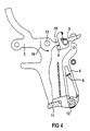
FIG 3 zeigt den ausgelösten Zustand, in dem der Vorsprung 10
des Winkelhebels 3 den Klinkenhebel 5 über seine Nase 9 in
der offenen Position hält. Der Zwischenhebel 4 ist im ausgelösten
Zustand in seiner Ausgangsstellung am Anschlag 16, in
der lediglich die Rückstellfeder 8 angreift. Im übrigen ist
der Zwischenhebel 4 um seinen Lagerpunkt 12 frei beweglich.3 shows the triggered state in which the
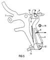
FIG 4 zeigt das Schaltschloß 1 in einer ersten Zwischenstellung
bei Reset, d.h. den Übergang von dem ausgelösten Zustand
in den EIN-Zustand, wobei die durch den Pfeil 18 angedeutete
Drehung des Winkelhebels 3 um den Lagerpunkt 13 erfolgt.4 shows the
Der Winkelhebel 3 liegt hier bereits auf der Rampe 11 des
Zwischenhebels 4 auf, der hierdurch bereits um einen kleinen
Winkel gegenüber seiner Ausgangsposition über die Verklinkungsstelle
17 hinaus gedreht ist. Zugleich hält der Winkelhebel
3 mit seinem Vorsprung 10 den Klinkenhebel 5 noch in
dessen offener Position. The
FIG 5 zeigt eine zweite Zwischenstellung beim Reset, in der
die Rückstellung des Klinkenhebels 4 in seine geschlossene
Position durch den Winkelhebel 3 freigegeben ist. Dabei befindet
sich der Winkelhebel 3 kurz vor dem Ende der Rampe 11,
d.h. er ist noch nicht an dem Zwischenhebel 4 verklinkt. Erst
bei Erreichen des Endes der Rampe 11 gibt der Winkelhebel 4
den Zwischenhebel 3 frei und der Zwischenhebel 4 wird durch
die Rückstellfeder 8 in Richtung Anschlag 16 zurückbewegt.
Dabei erfolgt die Verklinkung des Winkelhebels am Zwischenhebel
3 und die Verklinkung des Zwischenhebels 3 am Klinkenhebel
5 wie in FIG 1 und 2 dargestellt.5 shows a second intermediate position during the reset, in which
the return of the
Obwohl die vorliegende Erfindung unter Bezugnahme auf die in der beigefügten Zeichnung dargestellte Ausführungsform erläutert ist, sollte berücksichtigt werden, daß damit nicht beabsichtigt ist, die Erfindung nur auf die dargestellte Ausführungsform zu beschränken, sondern alle möglichen Änderungen, Modifizierungen und äquivalente Anordnungen, soweit sie vom Inhalt der Patentansprüche gedeckt sind, einzuschließen.Although the present invention with reference to the in of the accompanying drawing illustrated embodiment is, it should be borne in mind that this is not intended is, the invention only to the illustrated embodiment to limit, but all possible changes, Modifications and equivalent arrangements insofar as they are from Contents of the claims are covered.
Claims (4)
- Switch lock (1) for opening and closing contacts of a switching device, which has a bell-crank lever (3) for actuating a lock mechanism, a latch lever (5) and an intermediate lever (4), at which the bell-crank lever (3) latches in the ON position, in which the latching of the intermediate lever (4) by the latch lever (5) provided for as a release device simultaneously takes place, characterised in that the bell-crank lever (3), the latch lever (5) and the intermediate lever (4) are arranged such thata) the bell-crank lever (3) after release of the latch lever (5) moves this to its open position and retains this during the released state,b) in the released state there is no functional connection between the intermediate lever (4) and the bell-crank lever (3).
- Switch lock in accordance with claim 1, characterised in that the intermediate lever (4) is held by spring pressure against a stop (16) in the released state and on reset the intermediate lever (4) is first moved by the bell-crank lever (3) from the stop (16) past the latching point (17) before the latch lever (5), having been released by the bell-crank lever (3), lies against the intermediate lever (4) which then after release by the bell-crank lever (3) is moved back to the stop (16) and thus latches with the latch lever (5).
- Switch lock in accordance with claims 1 or 2, characterised in that the bell-crank lever (3) has a projection (10) which when released by a nose (9) formed on a latch lever (5) moves this to its open position.
- Switch lock in accordance with one of the preceding claims, characterised in that the intermediate lever (4) has a ramp (11) along which the bell-crank lever (3) slides on reset until latching on the intermediate lever (4).
Applications Claiming Priority (3)
| Application Number | Priority Date | Filing Date | Title |
|---|---|---|---|
| DE1997103972 DE19703972C1 (en) | 1997-02-03 | 1997-02-03 | Latching/breaker mechanism e.g. for circuit-breaker |
| DE19703972 | 1997-02-03 | ||
| PCT/DE1998/000200 WO1998034257A1 (en) | 1997-02-03 | 1998-01-22 | Latching mechanism of a switching device |
Publications (2)
| Publication Number | Publication Date |
|---|---|
| EP0956577A1 EP0956577A1 (en) | 1999-11-17 |
| EP0956577B1 true EP0956577B1 (en) | 2001-07-25 |
Family
ID=7819150
Family Applications (1)
| Application Number | Title | Priority Date | Filing Date |
|---|---|---|---|
| EP98909277A Expired - Lifetime EP0956577B1 (en) | 1997-02-03 | 1998-01-22 | Latching mechanism of a switching device |
Country Status (4)
| Country | Link |
|---|---|
| EP (1) | EP0956577B1 (en) |
| CN (1) | CN1163931C (en) |
| DE (1) | DE19703972C1 (en) |
| WO (1) | WO1998034257A1 (en) |
Families Citing this family (5)
| Publication number | Priority date | Publication date | Assignee | Title |
|---|---|---|---|---|
| DE10209262C1 (en) * | 2002-03-01 | 2003-12-24 | Moeller Gmbh | Latching mechanism for low voltage switches |
| KR100516943B1 (en) * | 2003-12-26 | 2005-09-23 | 엘에스산전 주식회사 | Structure of breaking apparatus for trip error protection of motor protected breaker and method of operating thereof |
| DE102006044119B4 (en) * | 2006-09-20 | 2018-03-08 | Eaton Industries Gmbh | Electrical switching device |
| CN102568922B (en) * | 2010-12-30 | 2015-02-11 | 中国船舶重工集团公司第七一三研究所 | Load signal generating mechanism |
| DE102012201260A1 (en) * | 2012-01-30 | 2013-08-01 | Siemens Aktiengesellschaft | Switching unit for an electrical switching device and electrical switching device |
Family Cites Families (7)
| Publication number | Priority date | Publication date | Assignee | Title |
|---|---|---|---|---|
| DE2851817C3 (en) * | 1978-04-19 | 1984-10-18 | Siemens AG, 1000 Berlin und 8000 München | Low-voltage circuit breaker with a main pawl, an intermediate pawl and a locking element |
| US4301346A (en) * | 1980-06-23 | 1981-11-17 | General Electric Company | Circuit breaker trip latch assembly |
| US4344054A (en) * | 1981-03-04 | 1982-08-10 | General Electric Company | Latch assembly for static trip circuit breakers |
| US4594491A (en) * | 1984-09-28 | 1986-06-10 | Westinghouse Electric Corp. | Molded case circuit breaker with a trip mechanism having an intermediate latch lever |
| US4789848A (en) * | 1987-09-03 | 1988-12-06 | General Electric Company | Molded case circuit breaker latch and operating mechanism assembly |
| DE9206137U1 (en) * | 1992-05-07 | 1993-09-09 | Siemens Ag | Circuit breaker with a switch lock |
| DE19526591B4 (en) * | 1995-07-21 | 2005-04-21 | Abb Patent Gmbh | Electric switch |
-
1997
- 1997-02-03 DE DE1997103972 patent/DE19703972C1/en not_active Expired - Fee Related
-
1998
- 1998-01-22 EP EP98909277A patent/EP0956577B1/en not_active Expired - Lifetime
- 1998-01-22 WO PCT/DE1998/000200 patent/WO1998034257A1/en active IP Right Grant
- 1998-01-22 CN CNB988014653A patent/CN1163931C/en not_active Expired - Fee Related
Also Published As
| Publication number | Publication date |
|---|---|
| CN1163931C (en) | 2004-08-25 |
| EP0956577A1 (en) | 1999-11-17 |
| WO1998034257A1 (en) | 1998-08-06 |
| CN1241290A (en) | 2000-01-12 |
| DE19703972C1 (en) | 1998-05-14 |
Similar Documents
| Publication | Publication Date | Title |
|---|---|---|
| EP0454963B1 (en) | Switching mechanism for low tension switchgear | |
| EP2634787B1 (en) | Switching lock of a circuit breaker | |
| DE2938858A1 (en) | SWITCHING MECHANISM FOR CIRCUIT BREAKER | |
| DE4304771C1 (en) | Switching device for multi-phase motor protection switch - cooperates with release lever of external auxiliary switch upon overcurrent release | |
| DE3505674C2 (en) | ||
| EP0956577B1 (en) | Latching mechanism of a switching device | |
| EP0956576B1 (en) | Switching device with tripped position of the latching mechanism | |
| EP0956579B1 (en) | Switching device with under-voltage auxiliary release | |
| EP0828277B1 (en) | Circuit breaker and linked auxiliary switch | |
| EP0956578B1 (en) | Fast connection switching device | |
| EP0091040B1 (en) | Protective excess current circuit-breaking switch | |
| DE2914743C2 (en) | Residual current circuit breaker | |
| DE3119165A1 (en) | Automatic circuit breaker as a structural unit consisting of a line protection circuit breaker as well as auxiliary and signal switches | |
| EP1005060B1 (en) | Undervoltage release device | |
| DE3903414C3 (en) | Switch combination consisting of main and auxiliary switches | |
| DE2904211C2 (en) | Residual current circuit breaker that is coupled to a line circuit breaker | |
| WO2000067275A1 (en) | Circuit breaker for multipolar release | |
| DE4106939C2 (en) | ||
| DE3009682A1 (en) | MULTIPOLE CIRCUIT BREAKER | |
| DE703630C (en) | Overcurrent circuit breaker with toggle handle | |
| DE2841821A1 (en) | DRIVE DEVICE FOR ELECTRIC CIRCUIT BREAKERS WITH SHORT BREAK | |
| DE4023655C2 (en) | Auxiliary switch arrangement for a manually operated motor protection switch | |
| DE102023104113A1 (en) | Differential lock for an electrical differential protection device | |
| AT281963B (en) | Circuit breaker | |
| DE2518093C2 (en) | Toggle shadow gear for automatic switch |
Legal Events
| Date | Code | Title | Description |
|---|---|---|---|
| PUAI | Public reference made under article 153(3) epc to a published international application that has entered the european phase |
Free format text: ORIGINAL CODE: 0009012 |
|
| 17P | Request for examination filed |
Effective date: 19990720 |
|
| AK | Designated contracting states |
Kind code of ref document: A1 Designated state(s): FR IT |
|
| GRAG | Despatch of communication of intention to grant |
Free format text: ORIGINAL CODE: EPIDOS AGRA |
|
| 17Q | First examination report despatched |
Effective date: 20000919 |
|
| GRAG | Despatch of communication of intention to grant |
Free format text: ORIGINAL CODE: EPIDOS AGRA |
|
| GRAH | Despatch of communication of intention to grant a patent |
Free format text: ORIGINAL CODE: EPIDOS IGRA |
|
| GRAH | Despatch of communication of intention to grant a patent |
Free format text: ORIGINAL CODE: EPIDOS IGRA |
|
| GRAA | (expected) grant |
Free format text: ORIGINAL CODE: 0009210 |
|
| AK | Designated contracting states |
Kind code of ref document: B1 Designated state(s): FR IT |
|
| EN | Fr: translation not filed | ||
| EN | Fr: translation not filed |
Free format text: BO 01/51 PAGES: 265, IL Y A LIEU DE SUPPRIMER: LA MENTION DE LA NON REMISE. LA REMISE EST PUBLIEE DANS LE PRESENT BOPI. |
|
| ET | Fr: translation filed | ||
| PLBE | No opposition filed within time limit |
Free format text: ORIGINAL CODE: 0009261 |
|
| STAA | Information on the status of an ep patent application or granted ep patent |
Free format text: STATUS: NO OPPOSITION FILED WITHIN TIME LIMIT |
|
| 26N | No opposition filed | ||
| PG25 | Lapsed in a contracting state [announced via postgrant information from national office to epo] |
Ref country code: IT Free format text: LAPSE BECAUSE OF NON-PAYMENT OF DUE FEES;WARNING: LAPSES OF ITALIAN PATENTS WITH EFFECTIVE DATE BEFORE 2007 MAY HAVE OCCURRED AT ANY TIME BEFORE 2007. THE CORRECT EFFECTIVE DATE MAY BE DIFFERENT FROM THE ONE RECORDED. Effective date: 20050122 |
|
| PGFP | Annual fee paid to national office [announced via postgrant information from national office to epo] |
Ref country code: FR Payment date: 20070123 Year of fee payment: 10 |
|
| REG | Reference to a national code |
Ref country code: FR Ref legal event code: ST Effective date: 20081029 |
|
| PG25 | Lapsed in a contracting state [announced via postgrant information from national office to epo] |
Ref country code: FR Free format text: LAPSE BECAUSE OF NON-PAYMENT OF DUE FEES Effective date: 20080131 |