EP0955440A2 - Door frame system for use in dry interior construction work - Google Patents
Door frame system for use in dry interior construction work Download PDFInfo
- Publication number
- EP0955440A2 EP0955440A2 EP99890145A EP99890145A EP0955440A2 EP 0955440 A2 EP0955440 A2 EP 0955440A2 EP 99890145 A EP99890145 A EP 99890145A EP 99890145 A EP99890145 A EP 99890145A EP 0955440 A2 EP0955440 A2 EP 0955440A2
- Authority
- EP
- European Patent Office
- Prior art keywords
- frame
- plasterboard
- wall
- area
- frame system
- Prior art date
- Legal status (The legal status is an assumption and is not a legal conclusion. Google has not performed a legal analysis and makes no representation as to the accuracy of the status listed.)
- Withdrawn
Links
Images

Classifications
-
- E—FIXED CONSTRUCTIONS
- E06—DOORS, WINDOWS, SHUTTERS, OR ROLLER BLINDS IN GENERAL; LADDERS
- E06B—FIXED OR MOVABLE CLOSURES FOR OPENINGS IN BUILDINGS, VEHICLES, FENCES OR LIKE ENCLOSURES IN GENERAL, e.g. DOORS, WINDOWS, BLINDS, GATES
- E06B5/00—Doors, windows, or like closures for special purposes; Border constructions therefor
- E06B5/10—Doors, windows, or like closures for special purposes; Border constructions therefor for protection against air-raid or other war-like action; for other protective purposes
- E06B5/16—Fireproof doors or similar closures; Adaptations of fixed constructions therefor
Definitions
- the invention relates to a frame system for dry interior construction, in which vertical C or U uprights are arranged between the floor area and the ceiling area and are clad on both sides with plasterboard.
- Doors with such resistance classes are heavy, with normal passage widths up to 150 kilograms and therefore place high mechanical demands on the frames and wall connection.
- the metal accumulations in the frame area create thermal bridges, which also have a negative impact on fire resistance.
- the invention aims to remedy this situation and to provide a frame wall connection system of the type mentioned that is suitable for doors of large masses, thus suitable for fire-retardant doors, easy to assemble and adjust and can also be installed after the completion of a wall .
- the frame with the stand assigned to it is provided in the rebate area by at least one plasterboard, which is arranged normal to the wall level is and extends essentially over the entire thickness of the plasterboard wall to connect, preferably screw.
- a closed profile is used as the vertical upright. This is also thermally insulated on the wall level with at least one layer of plasterboard on each side. In the area facing away from the fold of the frame, an insulating material, e.g. Glass or rock wool, introduced, so that the closed profile is thermally insulated on all sides.
- an insulating material e.g. Glass or rock wool
- This design on the one hand achieves a substantial increase in the mechanical strength of the frame itself, particularly in the area in which the greatest closing forces occur, for example when the door is being closed forcefully, and at the same time provides a particularly firm connection with the associated stand in this area , which is anchored to the floor and ceiling and has the necessary strength.
- the frame is also screwed to the stand assigned to it from at least one of the frame mirrors.
- a frame 1 consists of one in its basic features well-known frame profile with a trim frame.
- the frame reveal, which faces the plasterboard wall 3, is firmly connected by means of a screw 4 to the stand 5 assigned to the frame 1.
- At least one plasterboard, preferably several plasterboard panels with a thickness as required by the desired fire resistance class (two in the present example) is located between the frame rebate side and the stand 5 and thus creates excellent thermal protection for the statically important stand 5.
- the frame 1 is preferably also firmly connected on the side of the frame mirror with screws 6 to the stand 5 assigned to it, so that a noticeable deformation of the frame is restricted even under the influence of strong heating.
- the structure in the area of the lintel lintel is designed analogously to the area of the vertical frame parts, which means that a mechanically sufficiently dimensioned and anchored profile 7 must be provided above the frame, preferably extending from stand 5 to stand 5 .
- the frame has the shape shown.
- the frame mirrors can have different shapes and, particularly in the interior of the cavity, 2 materials can be provided that swell when exposed to heat and thus, under certain circumstances, contribute to a smoke-tight seal between the door leaf and the frame in addition to corresponding inserts in the door leaf.
- the cavity shown in FIG. 2 released on one side of the frame can also be completely or partially filled with heat-insulating and fire-retardant materials in order to further increase the resistance.
- the structure of the wall itself is not affected by the invention and corresponds to the normal dry interior, taking into account the fire resistance class aimed for in each case. It must be noted in particular with respect to FIGS. 2 and 3 that the "normal" fastening of the plasterboard to the stands 5 or supports 7 is not shown in the figures, since it has nothing to do with the invention and is completely state of the art Technology corresponds.
- a particular advantage of the exemplary embodiment shown is that the frames can still be installed even after the walls have been completed, which has a great advantage, as everyone knows who is familiar with the room operation on a construction site.
- frame connection systems in which the frame has to be installed with the plasterboard stand wall there is a great risk that the frame will be damaged in the course of further interior work and that it will be laboriously and costly repaired, possibly also having to be replaced, which often necessitates extensive dismantling work.
- the frame shown consists of two parts, which are each pushed on from the outside in the direction normal to the wall plane and screwed to the profile 5 by means of the screws 4, 6. In this way, additional screws in the region of the bend secure the connection between the two frame parts in a manner not shown.
- This wall connection system allows a modular construction with different wall thicknesses.
- the cross sections of the respective profile 5 are adapted to the wall thickness.
Abstract
Description
Die Erfindung betrifft ein Zargensystem für den trockenen Innenausbau, bei dem zwischen Bodenbereich und Deckenbereich vertikale C- bzw. U-Steher angeordnet sind, die beidseits mit Gipskartonplatten verkleidet sind.The invention relates to a frame system for dry interior construction, in which vertical C or U uprights are arranged between the floor area and the ceiling area and are clad on both sides with plasterboard.
Beim trockenen Innenausbau werden zwischen Boden und Decke bzw. an Boden und Decke montierten horizontalen Profilen vertikale C- bzw. U-Steher aus Metall vorgesehen, die beidseits mit Gipskartonplatten verkleidet werden. In vielen Fällen sind zumindest im Boden- und Deckenbereich auch horizontale Elemente angeordnet, um zur notwendigen Steifigkeit zu kommen. Aufgrund der guten Brandwiderstandsfähigkeit von Gipskartonplatten erreicht man mit derartigen Wänden Brandwiderstandsklassen bis 120 Minuten, doch bilden dabei gemäß dem Stand der Technik Türen in derartigen Wänden immer Problemzonen, was auf die folgenden Gründe zurückzuführen ist:In dry interior construction, vertical C or U posts made of metal are provided between floor and ceiling or horizontal profiles mounted on floor and ceiling, which are clad on both sides with plasterboard. In many cases, horizontal elements are also arranged at least in the floor and ceiling area in order to achieve the necessary rigidity. Due to the good fire resistance of plasterboard, fire resistance classes of up to 120 minutes can be achieved with such walls, but according to the prior art, doors in such walls always form problem areas, which can be attributed to the following reasons:
Türen, die über derartige Widerstandsklassen verfügen, sind schwer, bei normalen Durchgangsbreiten bereits bis 150 Kilogramm und stellen daher an die verwendeten Zargen und den Wandanschluß hohe mechanische Anforderungen. Dazu kommt, daß durch die Metallanhäufungen im Zargenbereich Wärmebrücken geschaffen werden, die sich ebenfalls negativ auf den Brandwiderstand auswirken.Doors with such resistance classes are heavy, with normal passage widths up to 150 kilograms and therefore place high mechanical demands on the frames and wall connection. In addition, the metal accumulations in the frame area create thermal bridges, which also have a negative impact on fire resistance.
Es gibt vorbekannte Lösungen zur Erzielung derartiger Brandwiderstandsklassen im trocknen Innenausbau im Türbereich, doch sind diese Lösungen aus einer Vielzahl von einzelnen Bauteilen aufgebaut und entsprechend kompliziert zu montieren und zu justieren.There are previously known solutions for achieving such fire resistance classes in dry interior fittings in the door area, but these solutions are made up of a large number of individual components and are correspondingly complicated to assemble and adjust.
Es ist aus der FR 2 711 176 A bekannt, eine Hilfszarge von der Wandseite her mit einem benachbarten vertikalen Träger zu verschrauben und so die Ränder der Gipskartonplatten während des weiteren Baufortschrittes zu schützen. Schließlich wird die eigentliche Zarge auf die Hilfszarge aufgeschnappt und die Türe eingesetzt. Wie oben ausgeführt, ist eine solche Konstruktion für schwere, brandhemmende Türen völlig ungeeignet. Durch die notwendige Montage der Hilfszarge von der Wand her, ist ein nachträgliches Anbringen der Türe nicht möglich.It is known from FR 2 711 176 A to screw an auxiliary frame from the wall side to an adjacent vertical support and thus the edges of the plasterboard to protect as construction progresses. Finally, the actual frame is snapped onto the auxiliary frame and the door is inserted. As stated above, such a construction is completely unsuitable for heavy, fire-retardant doors. Due to the necessary installation of the auxiliary frame from the wall, retrofitting the door is not possible.
Aus der US 3,969,846 ist ein Scharnier für zargenlose Türen bekannt, das für Holzgebäude beschrieben wird, aber bei allen Arten von Türen verwendet werden kann, bei denen relativ stabile vertikale Ständer unmittelbar im Türbereich zu finden sind. Für brandhemmende Türen mit ihren großen Massen ist die aus dieser Druckschrift bekannte Konstruktion völlig ungeeignet, ebenso für das Vorsehen einer Zarge selbst.From US 3,969,846 a hinge for frameless doors is known, which is described for wooden buildings, but can be used for all types of doors in which relatively stable vertical stands can be found directly in the door area. The construction known from this publication is completely unsuitable for fire-retardant doors with their large masses, and also for the provision of a frame itself.
Aus der US 4,443,984 ist eine Türe für den trockenen Innenausbau bekannt, das insbesondere für begehbare Schränke u.dergl. gedacht ist und aus einer Vielzahl einzelner Profile und Leisten besteht, die an Ort und Stelle zusammengebaut werden müssen. Für die Ausbildung einer brandhemmenden Türe ist diese Konstruktion sowenig geeignet wie für eine nachträgliche Anbringung der Zarge, da die Gipskartonabdeckungen durch die Zarge durch montiert werden.From US 4,443,984 a door for dry interior construction is known, especially for walk-in closets and the like. is intended and consists of a large number of individual profiles and strips that have to be assembled on site. This construction is as unsuitable for the formation of a fire-retardant door as for a subsequent attachment of the frame, since the plasterboard covers are installed through the frame.
Die Erfindung bezweckt, hier Abhilfe zu schaffen und ein Zargen-Wandanschlußsystem der eingangs genannten Art zu schaffen, das für Türen großer Massen, somit für brandhemmende Türen geeignet, einfach zu montieren und zu justieren ist und auch nachträglich, nach Fertigstellung einer Wand, montierbar ist.The invention aims to remedy this situation and to provide a frame wall connection system of the type mentioned that is suitable for doors of large masses, thus suitable for fire-retardant doors, easy to assemble and adjust and can also be installed after the completion of a wall .
Erfindungsgemäß wird dazu vorgesehen, im Falzbereich die Zarge mit dem ihr zugeordneten Ständer durch zumindest eine Gipskartonplatte, die normal zur Mauerebene angeordnet ist und im wesentlichen sich über die gesamte Stärke der Gipskartonwand erstreckt, zu verbinden, bevorzugt zu verschrauben.According to the invention, the frame with the stand assigned to it is provided in the rebate area by at least one plasterboard, which is arranged normal to the wall level is and extends essentially over the entire thickness of the plasterboard wall to connect, preferably screw.
Statt des üblichen C- oder U-Profils im Bereich der Zarge wird als Vertikalsteher ein geschlossenes Profil verwendet. Dieses wird auch in der Wandebene mit zumindest einer Lage Gipskartonplatten auf jeder Seite thermisch zusätzlich isoliert. Bevorzugt wird im Bereich, der dem Falz der Zarge abgewandt ist, ein Isoliermaterial, z.B. Glas- oder Steinwolle, eingebracht, sodaß das geschlossene Profil allseits hervorragend thermisch isoliert ist.Instead of the usual C or U profile in the area of the frame, a closed profile is used as the vertical upright. This is also thermally insulated on the wall level with at least one layer of plasterboard on each side. In the area facing away from the fold of the frame, an insulating material, e.g. Glass or rock wool, introduced, so that the closed profile is thermally insulated on all sides.
Durch diese Ausbildung erreicht man einerseits eine wesentliche Erhöhung der mechanischen Festigkeit der Zarge selbst, gerade in dem Bereich, in dem die größten Schließkräfte, beispielsweise beim kraftvollen Schließen der Türe, auftreten und erhält gleichzeitig gerade in diesem Bereich eine besonders feste Verbindung mit dem zugeordneten Ständer, der am Boden und in der Decke verankert ist und über die notwendige Festigkeit verfügt.This design on the one hand achieves a substantial increase in the mechanical strength of the frame itself, particularly in the area in which the greatest closing forces occur, for example when the door is being closed forcefully, and at the same time provides a particularly firm connection with the associated stand in this area , which is anchored to the floor and ceiling and has the necessary strength.
In einer Ausgestaltung ist vorgesehen, daß zumindest von einem der Zargenspiegel her die Zarge ebenfalls mit dem ihr zugeordneten Ständer verschraubt ist.In one embodiment it is provided that the frame is also screwed to the stand assigned to it from at least one of the frame mirrors.
Die Erfindung wird im folgenden an Hand der Zeichnung näher erläutert. Dabei zeigt
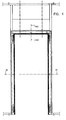
- die Fig. 1 ein in eine Gipskartonwand eingebautes erfindungsgemäßes Zarge-Wandanschlußsystem,
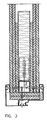
- die Fig. 2 einen Schnitt gemäß der Linie II-II der Fig. 1 und
- die Fig. 3 einen Schnitt entlang der Linie III-III der Fig. 1.
- 1 shows a frame wall connection system according to the invention installed in a plasterboard wall,
- 2 shows a section along the line II-II of FIG. 1 and
- 3 shows a section along the line III-III of FIG. 1st
Wie insbesondere aus Fig. 2 hervorgeht, besteht eine erfindungsgemäße Zarge 1 aus einem in seinen Grundzügen an sich bekannten Zargenprofil mit einer Verkleidungszarge. Die Zargenleibung, die der Gipskartonwand 3 zugewandt ist, ist mittels einer Schraube 4 mit dem der Zarge 1 zugeordneten Ständer 5 fest verbunden. Zwischen der Zargenfalzseite und dem Ständer 5 befindet sich zumindest ein Gipskarton, bevorzugt mehrere Gipskartonplatten mit einer solchen Stärke, wie es die angestrebte Brandwiderstandsklasse erfordert (im vorliegenden Beispiel somit zwei) und schafft so einen hervorragenden thermischen Schutz für den statisch wichtigen Ständer 5.As can be seen in particular from FIG. 2, a frame 1 according to the invention consists of one in its basic features well-known frame profile with a trim frame. The frame reveal, which faces the
Die Zarge 1 ist bevorzugt auch an der Seite der Zargenspiegel mit Schrauben 6 mit dem ihr zugeordneten Ständer 5 fest verbunden, so daß auch unter dem Einfluß starker Erhitzung ein merkliches Deformieren der Zarge eingeschränkt wird.The frame 1 is preferably also firmly connected on the side of the frame mirror with screws 6 to the
Wie aus der Fig. 3 ersichtlich, ist im Bereich des Zargensturzes der Aufbau analog zum Bereich der vertikalen Zargenteile gestaltet, dies bedeutet, daß oberhalb der Zarge ein mechanisch ausreichend dimensioniertes und verankertes Profil 7 vorgesehen sein muß, bevorzugt von Ständer 5 zu Ständer 5 reichend.As can be seen from FIG. 3, the structure in the area of the lintel lintel is designed analogously to the area of the vertical frame parts, which means that a mechanically sufficiently dimensioned and anchored
Es ist selbstverständlich nicht notwendig, daß die Zarge die dargestellte Form aufweist. So können die Zargenspiegel unterschiedliche Form aufweisen und es können besonders im Inneren des Hohlraumes 2 Materialien vorgesehen sein, die bei Hitzeeinwirkung aufquellen und so unter Umständen zusätzlich zu entsprechenden Einlagen im Türblatt zu einer rauchdichten Versiegelung zwischen dem Türblatt und der Zarge beitragen.It is of course not necessary that the frame has the shape shown. For example, the frame mirrors can have different shapes and, particularly in the interior of the cavity, 2 materials can be provided that swell when exposed to heat and thus, under certain circumstances, contribute to a smoke-tight seal between the door leaf and the frame in addition to corresponding inserts in the door leaf.
Es kann auch der in der Fig. 2 freigelassen dargestellte Hohlraum auf der einen Seite der Zarge mit wärmedämmenden und brandhemmenden Materialien ganz oder teilweise gefüllt sein, um die Widerstandskraft weiter zu erhöhen.The cavity shown in FIG. 2 released on one side of the frame can also be completely or partially filled with heat-insulating and fire-retardant materials in order to further increase the resistance.
Der Aufbau der Wand selbst wird von der Erfindung nicht berührt und entspricht dem normalen trockenen Innenausbau unter Berücksichtigung der jeweils angestrebten Brandwiderstandsklasse. Es muß insbesondere zu den Fig. 2 und 3 bemerkt werden, daß die "normale" Befestigung der Gipskartonplatten an den Ständern 5 bzw. Trägern 7 in den Figuren nicht dargestellt ist, da sie mit der Erfindung nichts zu tun hat und völlig dem Stand der Technik entspricht.The structure of the wall itself is not affected by the invention and corresponds to the normal dry interior, taking into account the fire resistance class aimed for in each case. It must be noted in particular with respect to FIGS. 2 and 3 that the "normal" fastening of the plasterboard to the
Ein besonderer Vorteil des dargestellten Ausführungsbeispieles liegt darin, daß die Zargen auch nach Fertigstellung der Wände noch montiert werden können, was einen großen Vorteil mit sich bringt, wie jeder weiß, der mit dem Raumbetrieb auf einer Baustelle vertraut ist. Bei Zargenanschlußsystemen, bei denen die Zarge mit der Gipskartonständerwand montiert werden muß, besteht die große Gefahr, daß im Zuge des weiteren Innenausbaus die Zarge beschädigt wird und umständlich und kostspielig ausgebessert, gegebenenfalls auch ersetzt werden muß, was oft große Demontagearbeiten notwendig macht.A particular advantage of the exemplary embodiment shown is that the frames can still be installed even after the walls have been completed, which has a great advantage, as everyone knows who is familiar with the room operation on a construction site. In the case of frame connection systems in which the frame has to be installed with the plasterboard stand wall, there is a great risk that the frame will be damaged in the course of further interior work and that it will be laboriously and costly repaired, possibly also having to be replaced, which often necessitates extensive dismantling work.
Die dargestellte Zarge besteht aus zwei Teilen, die jeweils von außen in Richtung normal zur Wandebene aufgeschoben und mittels der Schrauben 4, 6 mit dem Profil 5 verschraubt werden. Dabei sichern in nicht dargestellter Weise weitere Schrauben im Bereich der Umbiegung die Verbindung zwischen den beiden Zargenteilen.The frame shown consists of two parts, which are each pushed on from the outside in the direction normal to the wall plane and screwed to the
Dieses Wandanschlußsystem erlaubt einen baukastenartigen Aufbau bei unterschiedlicher Wandstärke. Dabei werden die Querschnitte des jeweiligen Profils 5 der Wandstärke angepaßt.This wall connection system allows a modular construction with different wall thicknesses. The cross sections of the
Durch die Verwendung des geschlossenen Profils können auch bei dünnen Wänden, z.B. von 125 mm, Brandwiderstansklassen von 120 min erreicht werden.By using the closed profile, even with thin walls, e.g. of 125 mm, fire resistance classes of 120 min.
Claims (2)
Applications Claiming Priority (2)
| Application Number | Priority Date | Filing Date | Title |
|---|---|---|---|
| AT74198 | 1998-05-05 | ||
| AT74198 | 1998-05-05 |
Publications (2)
| Publication Number | Publication Date |
|---|---|
| EP0955440A2 true EP0955440A2 (en) | 1999-11-10 |
| EP0955440A3 EP0955440A3 (en) | 2000-03-29 |
Family
ID=3498585
Family Applications (1)
| Application Number | Title | Priority Date | Filing Date |
|---|---|---|---|
| EP99890145A Withdrawn EP0955440A3 (en) | 1998-05-05 | 1999-05-04 | Door frame system for use in dry interior construction work |
Country Status (4)
| Country | Link |
|---|---|
| EP (1) | EP0955440A3 (en) |
| CZ (1) | CZ160599A3 (en) |
| HU (1) | HUP9901492A3 (en) |
| PL (1) | PL332933A1 (en) |
Cited By (2)
| Publication number | Priority date | Publication date | Assignee | Title |
|---|---|---|---|---|
| CN101748963A (en) * | 2008-12-19 | 2010-06-23 | 方大集团股份有限公司 | Full-height railway shielding door upright column and adjusting device thereof |
| CN101818602B (en) * | 2010-01-08 | 2012-10-03 | 深圳市方大自动化系统有限公司 | Insulating structure of subway shielding door system and civil engineering structure |
Citations (3)
| Publication number | Priority date | Publication date | Assignee | Title |
|---|---|---|---|---|
| US3969846A (en) | 1974-10-23 | 1976-07-20 | Delbert Scott | Door hinge |
| US4443984A (en) | 1981-06-25 | 1984-04-24 | Rasmussen Robert R | Door, window, and partition casing arrangement for dry wall partitions |
| FR2711176A1 (en) | 1993-10-15 | 1995-04-21 | Placoplatre Sa | Method of mounting a door unit in a partition formed by a frame on which plasterboards have been fixed, and door unit enabling the implementation of such a method |
Family Cites Families (2)
| Publication number | Priority date | Publication date | Assignee | Title |
|---|---|---|---|---|
| US4281481A (en) * | 1980-01-18 | 1981-08-04 | United States Gypsum Company | Fire resistant aluminum door frame assembly |
| FR2721343B1 (en) * | 1994-06-16 | 1996-09-13 | Malerba Dugelet | Open profile frame, fitted with an insulation gasket. |
-
1999
- 1999-05-03 HU HU9901492A patent/HUP9901492A3/en unknown
- 1999-05-04 EP EP99890145A patent/EP0955440A3/en not_active Withdrawn
- 1999-05-04 PL PL99332933A patent/PL332933A1/en unknown
- 1999-05-05 CZ CZ991605A patent/CZ160599A3/en unknown
Patent Citations (3)
| Publication number | Priority date | Publication date | Assignee | Title |
|---|---|---|---|---|
| US3969846A (en) | 1974-10-23 | 1976-07-20 | Delbert Scott | Door hinge |
| US4443984A (en) | 1981-06-25 | 1984-04-24 | Rasmussen Robert R | Door, window, and partition casing arrangement for dry wall partitions |
| FR2711176A1 (en) | 1993-10-15 | 1995-04-21 | Placoplatre Sa | Method of mounting a door unit in a partition formed by a frame on which plasterboards have been fixed, and door unit enabling the implementation of such a method |
Cited By (3)
| Publication number | Priority date | Publication date | Assignee | Title |
|---|---|---|---|---|
| CN101748963A (en) * | 2008-12-19 | 2010-06-23 | 方大集团股份有限公司 | Full-height railway shielding door upright column and adjusting device thereof |
| CN101748963B (en) * | 2008-12-19 | 2013-03-20 | 深圳市方大自动化系统有限公司 | Full-height railway shielding door upright column system |
| CN101818602B (en) * | 2010-01-08 | 2012-10-03 | 深圳市方大自动化系统有限公司 | Insulating structure of subway shielding door system and civil engineering structure |
Also Published As
| Publication number | Publication date |
|---|---|
| HU9901492D0 (en) | 1999-07-28 |
| PL332933A1 (en) | 1999-11-08 |
| CZ160599A3 (en) | 1999-11-17 |
| HUP9901492A3 (en) | 2001-06-28 |
| EP0955440A3 (en) | 2000-03-29 |
| HUP9901492A2 (en) | 2001-02-28 |
Similar Documents
| Publication | Publication Date | Title |
|---|---|---|
| EP1115953B1 (en) | Fire wall | |
| EP0549769B1 (en) | Fire-resistant glass partition | |
| EP3080375B2 (en) | Device for closing an opening in a building | |
| EP0551307B1 (en) | Door leaf and process for producing the same | |
| WO2001007745A9 (en) | Fire door with a doorframe surrounding said door | |
| EP2666948A1 (en) | Frame assembly for a panel for sectional doors | |
| DE3210253A1 (en) | Window construction | |
| EP1657397B1 (en) | Glazed doorleaf and glazed door with such a doorleaf | |
| CH665679A5 (en) | DOOR OR GATE WITH AT LEAST ONE INSULATED WING, IN PARTICULAR FIRE PROTECTION GATE. | |
| EP1586734B1 (en) | Glazed fire resistant door | |
| DE69630874T2 (en) | ASSEMBLY DEVICE FOR LARGE PIECES, IN PARTICULAR BALCONY GLASS PANELS | |
| EP0955440A2 (en) | Door frame system for use in dry interior construction work | |
| EP2180125A2 (en) | Window or door frame | |
| EP0324209A1 (en) | Wall board | |
| EP1391567A2 (en) | Heat insulating element for building facades and installation method | |
| DE102008027622A1 (en) | Window structure for inserting in a window opening in a building's supporting-wall section has a window stem and fastening devices with a stiff peripheral supporting frame | |
| DE102007027807A1 (en) | Dry construction partition wall for changing room usage, has inspection glass formed as fire protection inspection glass, where inspection glass is supported on frame by elastic spring unit i.e. rock wool layer, in floating suspension | |
| EP0902154B1 (en) | Fireproof glazing | |
| EP0125445B1 (en) | Door casing consisting of a wood-covered metal door frame | |
| DE19709938A1 (en) | Window arrangement with glazing on support in window embrasure | |
| EP1015724B1 (en) | Three-piece metal door case | |
| WO2007009612A1 (en) | Sliding door element | |
| AT383862B (en) | FRAME FOR WINDOWS, DOORS OR THE LIKE. | |
| AT526254B1 (en) | Receiving element for a shading device | |
| EP1044920A2 (en) | Fireproof elevator shaft doors |
Legal Events
| Date | Code | Title | Description |
|---|---|---|---|
| PUAI | Public reference made under article 153(3) epc to a published international application that has entered the european phase |
Free format text: ORIGINAL CODE: 0009012 |
|
| AK | Designated contracting states |
Kind code of ref document: A2 Designated state(s): AT BE CH CY DE DK ES FI FR GB GR IE IT LI LU MC NL PT SE |
|
| AX | Request for extension of the european patent |
Free format text: AL;LT;LV;MK;RO;SI |
|
| PUAL | Search report despatched |
Free format text: ORIGINAL CODE: 0009013 |
|
| AK | Designated contracting states |
Kind code of ref document: A3 Designated state(s): AT BE CH CY DE DK ES FI FR GB GR IE IT LI LU MC NL PT SE |
|
| AX | Request for extension of the european patent |
Free format text: AL;LT;LV;MK;RO;SI |
|
| AKX | Designation fees paid | ||
| REG | Reference to a national code |
Ref country code: DE Ref legal event code: 8566 |
|
| STAA | Information on the status of an ep patent application or granted ep patent |
Free format text: STATUS: THE APPLICATION IS DEEMED TO BE WITHDRAWN |
|
| 18D | Application deemed to be withdrawn |
Effective date: 20000930 |