EP0953773B1 - A pump for liquids, in particular for the cooling circuit of an internal combustion engine - Google Patents
A pump for liquids, in particular for the cooling circuit of an internal combustion engine Download PDFInfo
- Publication number
- EP0953773B1 EP0953773B1 EP19990108411 EP99108411A EP0953773B1 EP 0953773 B1 EP0953773 B1 EP 0953773B1 EP 19990108411 EP19990108411 EP 19990108411 EP 99108411 A EP99108411 A EP 99108411A EP 0953773 B1 EP0953773 B1 EP 0953773B1
- Authority
- EP
- European Patent Office
- Prior art keywords
- duct
- outlet duct
- pump according
- liquid
- outlet
- Prior art date
- Legal status (The legal status is an assumption and is not a legal conclusion. Google has not performed a legal analysis and makes no representation as to the accuracy of the status listed.)
- Expired - Lifetime
Links
Images


Classifications
-
- F—MECHANICAL ENGINEERING; LIGHTING; HEATING; WEAPONS; BLASTING
- F01—MACHINES OR ENGINES IN GENERAL; ENGINE PLANTS IN GENERAL; STEAM ENGINES
- F01P—COOLING OF MACHINES OR ENGINES IN GENERAL; COOLING OF INTERNAL-COMBUSTION ENGINES
- F01P7/00—Controlling of coolant flow
- F01P7/14—Controlling of coolant flow the coolant being liquid
- F01P7/16—Controlling of coolant flow the coolant being liquid by thermostatic control
- F01P7/161—Controlling of coolant flow the coolant being liquid by thermostatic control by bypassing pumps
-
- F—MECHANICAL ENGINEERING; LIGHTING; HEATING; WEAPONS; BLASTING
- F04—POSITIVE - DISPLACEMENT MACHINES FOR LIQUIDS; PUMPS FOR LIQUIDS OR ELASTIC FLUIDS
- F04D—NON-POSITIVE-DISPLACEMENT PUMPS
- F04D15/00—Control, e.g. regulation, of pumps, pumping installations or systems
- F04D15/0005—Control, e.g. regulation, of pumps, pumping installations or systems by using valves
- F04D15/0011—Control, e.g. regulation, of pumps, pumping installations or systems by using valves by-pass valves
-
- F—MECHANICAL ENGINEERING; LIGHTING; HEATING; WEAPONS; BLASTING
- F04—POSITIVE - DISPLACEMENT MACHINES FOR LIQUIDS; PUMPS FOR LIQUIDS OR ELASTIC FLUIDS
- F04D—NON-POSITIVE-DISPLACEMENT PUMPS
- F04D15/00—Control, e.g. regulation, of pumps, pumping installations or systems
- F04D15/0005—Control, e.g. regulation, of pumps, pumping installations or systems by using valves
- F04D15/0016—Control, e.g. regulation, of pumps, pumping installations or systems by using valves mixing-reversing- or deviation valves
-
- F—MECHANICAL ENGINEERING; LIGHTING; HEATING; WEAPONS; BLASTING
- F01—MACHINES OR ENGINES IN GENERAL; ENGINE PLANTS IN GENERAL; STEAM ENGINES
- F01P—COOLING OF MACHINES OR ENGINES IN GENERAL; COOLING OF INTERNAL-COMBUSTION ENGINES
- F01P2025/00—Measuring
- F01P2025/08—Temperature
- F01P2025/32—Engine outcoming fluid temperature
-
- F—MECHANICAL ENGINEERING; LIGHTING; HEATING; WEAPONS; BLASTING
- F01—MACHINES OR ENGINES IN GENERAL; ENGINE PLANTS IN GENERAL; STEAM ENGINES
- F01P—COOLING OF MACHINES OR ENGINES IN GENERAL; COOLING OF INTERNAL-COMBUSTION ENGINES
- F01P2070/00—Details
Definitions
- the present invention relates to a pump for liquids, in particular for the cooling circuit of an internal combustion engine.
- the subject of the invention is a pump which includes a casing with an inlet duct and a (first) outlet duct for the liquid and a chamber defined between them in which a bladed impeller is mounted for rotation, operable to cause a flow of liquid from the inlet duct to the outlet duct.
- Cooling systems for internal combustion engines have been proposed which include a hydraulic circuit with a variable-flow electric pump, a radiator connected to the engine, a by-pass duct which is essentially parallel to the radiator, an automatic valve for regulating the ratio between the flows of liquid fed to the engine through the radiator and through the by-pass duct respectively, and a control unit operable to control the pump so as to vary the flow in dependence on the temperature of the liquid flowing through the circuit, as measured by a sensor.
- a cooling system is known e.g. from JP 57 002417 A.
- One object of the invention is to provide a pump for a cooling system of the aforesaid type, which enables the hydraulic connections required between the components of the system to be radically simplified, and which significantly improves the reliability of the system.
- an internal combustion engine of a motor vehicle for example, is indicated E.
- a cooling system is associated with the said engine.
- This system comprises a hydraulic circuit for supplying a flow of cooling liquid to the engine E.
- the cooling liquid can be a mixture of water and anti-freeze and anti-corrosion agents, for example.
- the hydraulic cooling circuit includes a pumping assembly generally indicated 1, which includes an electric pump 2, of a rotary type, the flow thereof being variable in dependence on variation in the speed of rotation of the impeller.
- the assembly 1 also includes an outlet distributor device 3 connected to the outlet or delivery 2b of the electric pump 2.
- the inlet 2a of the electric pump 2 is connected to an outlet 4 for the coolant liquid of the engine E.
- a radiator (a liquid/air heat exchanger), is indicated 5 with the inlet thereof connected to an outlet duct 3b of the outlet distributor device 3.
- This outlet duct 3b is able to communicate with the intake duct 2a of the electric pump 2 by means of a by-pass duct or passage 8 and a regulating valve 9.
- the outlet of the radiator 5 is connected to an inlet 6 for the coolant liquid of the engine E.
- a by-pass duct, indicated 7, is connected in parallel with the radiator 5, between an outlet duct 3a of the distributor 3 and the inlet 6 of the engine E.
- the duct 3a is in permanent communication with the outlet or delivery 2b of the pump 2.
- the by-pass duct 7 could extend through a heat exchanger (not illustrated), for heating the air flowing into the passenger compartment of the vehicle, for example.
- an electric temperature sensor is indicated 11.
- the sensor 11 is arranged near the inlet 6 for coolant liquid for the engine E.
- This temperature sensor could be arranged elsewhere, for example adjacent the outlet 4 of the engine E, or inside the engine E or at another predetermined point along the fluid circuit carrying the coolant.
- the temperature sensor 11 is connected to an electronic control unit, indicated 12.
- This unit 12 is connected to the electric motor which drives the pump 2, and is operable to control the said pump so that the delivery thereof varies according to predetermined instructions in dependence on the temperature measured by the sensor 11.
- the regulation valve 9 is operable to modify the ratio of the flows of coolant liquid supplied to the engine E through the radiator 5 and through the by-pass duct 7 respectively.
- the pump assembly 1 includes an electric pump 2, driven by an electric motor 10
- the electric pump 2 comprises a spiral casing, generally indicated 13, which is preferably moulded in one piece from plastics material.
- the inlet duct 2a of the electric pump 2 is formed in the upper portion of the spiral casing 13 of the electric pump 2. This duct opens (see Figure 3) into an inner chamber 14 of the spiral casing 13 in which an impeller 15 having a plurality of angularly spaced blades 16 is mounted for rotation.
- the chamber 14 has an outlet aperture or peripheral passage 2b, formed in one piece with the spiral casing 13 and to which the outlet duct 3a is connected.
- this outlet duct is inclined upwardly, so as to extend upwardly from the outlet of the pumping chamber 14 to the level of the inlet duct 2a of the spiral casing.
- the second outlet duct 3b opens off a side portion of the outlet duct 3a and extends essentially perpendicular thereto.
- a control chamber 17, which is essentially cylindrical in the embodiment illustrated, is formed in such a way that the lateral wall thereof is essentially tangential to the wall of the inlet duct 2a (see Figures 3 and 4 in particular).
- the chamber 17 is aligned axially with the outlet duct 3b and opens into the outlet duct 3a, facing the opening of the duct 3b.
- control chamber 17 communicates with the inlet duct 2a through an aperture or slot, indicated 8 in Figures 2 to 4, formed in the region of tangency between their walls.
- regulating valve means 9 are associated with the duct 3b.
- the valve means 9 are sensitive to the difference in pressure between the outlet duct 3a and the inlet duct 2a of the spiral casing, and are prearranged to allow liquid to flow through the outlet duct 3b (and thus through the radiator 5) once this pressure difference is greater than a predetermined value.
- the regulating valve means 9 include a valve member 20 able to cooperate, substantially as a shutter, with the opening of the outlet duct 3b.
- This valve member 20 is connected by a rod 21 to a piston 22 sealingly slidably mounted in the portion of the control chamber 17 downstream of the passage 8.
- the piston 22 is subject on one side to the pressure of the liquid flowing into the control chamber 17 from the inlet duct 2a, through the by-pass passage 8. On the other side, the piston 22 is subject to the pressure of the liquid flowing through the outlet duct 3a.
- a spring 23 is interposed between the valve member 20 and a stop 24 formed in the outlet duct 3b. This spring 23 tends to maintain the valve member 20 engaged against the mouth or entrance of the duct 3b.
- valve member 20 closes the opening of the duct 3b.
- the control unit 12 controls the electric pump to rotate at a moderate speed of rotation, whereby the pressure difference acting on the opposite sides of the piston 22 is not sufficient to overcome the action of the spring 23. Under these conditions, the pump 2 causes coolant liquid to flow to the engine E through the by-pass duct 7 alone.
- the control unit 12 shifts the electric pump 2 to a speed of rotation at which the pressure difference acting on the opposite sides of the piston 22 causes this latter to move whereby the valve 20 moves away from the opening of the outlet duct 3b. Under this condition, a portion of the liquid flowing from the electric pump 2 enters the outlet duct 3b and flows through the radiator 5. Therefore, a mixed flow of relatively cold liquid, from the radiator 5, and relatively warm liquid, from the by-pass duct 7, reaches the inlet 6 of the engine E.
- the control unit 12 is set to control the speed of rotation of the pump 2 so as to regulate the temperature of the fluid supplied to the engine E in the desired manner.
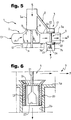
- FIG. 5 shows a variant of the pumping assembly 1, and in particular the spiral casing 13.
- parts and elements that have already been described are indicated once again by the same numbers.
- the by-pass passage 8 is constituted by a duct which is inclined to the axis of the inlet duct 2a and extends towards the outlet duct 3a. This arrangement enables the outlet duct 3a to be maintained substantially on the same plane as the chamber of the impeller 15. If the inclination is right, the by-pass duct 8 can be formed in one piece with the spiral casing 13.
- FIG. 6 shows an alternative embodiment of the valve 20.
- the valve 20 not only acts as a shutter but is able to increase the flow of liquid through the outlet duct 3b at a predetermined rate as it moves away from the associated opening of the duct 3b.
- the valve 20 has an essentially cylindrical sleeve 25, closed at the top by a transverse wall 26.
- the side wall of the sleeve 25, which extends into the duct 3b one or more apertures 27 are formed, shaped so as to allow a gradual increase of the flow of liquid into the duct 3b during the upward movement of the valve member 20.
Description
- The present invention relates to a pump for liquids, in particular for the cooling circuit of an internal combustion engine.
- More specifically, the subject of the invention is a pump which includes a casing with an inlet duct and a (first) outlet duct for the liquid and a chamber defined between them in which a bladed impeller is mounted for rotation, operable to cause a flow of liquid from the inlet duct to the outlet duct.
- Cooling systems for internal combustion engines have been proposed which include a hydraulic circuit with a variable-flow electric pump, a radiator connected to the engine, a by-pass duct which is essentially parallel to the radiator, an automatic valve for regulating the ratio between the flows of liquid fed to the engine through the radiator and through the by-pass duct respectively, and a control unit operable to control the pump so as to vary the flow in dependence on the temperature of the liquid flowing through the circuit, as measured by a sensor. Such a cooling system is known e.g. from JP 57 002417 A.
- One object of the invention is to provide a pump for a cooling system of the aforesaid type, which enables the hydraulic connections required between the components of the system to be radically simplified, and which significantly improves the reliability of the system.
- This and other objects are achieved by providing a pump having the main characteristics as defined in
Claim 1. - Additional characteristics and advantages of the invention will become clear from the detailed description which follows, with reference to the appended drawings in which:
- Figure 1 is a schematic illustration of a cooling system for an internal combustion engine, which includes a pump according to the invention;
- Figure 2 is a perspective view of a pump according to the invention;
- Figure 3 is a view sectioned along the line III-III of Figure 2;
- Figure 4 is a view partially sectioned along the line IV-IV of Figure 3;
- Figure 5 is a sectioned view of a further pump according to the invention; and
- Figure 6 is a sectioned view illustrating one way of making a valve in a pump according to the invention.
-
- In Figure 1, an internal combustion engine, of a motor vehicle for example, is indicated E. A cooling system, generally indicated CS, is associated with the said engine. This system comprises a hydraulic circuit for supplying a flow of cooling liquid to the engine E. The cooling liquid can be a mixture of water and anti-freeze and anti-corrosion agents, for example.
- In the embodiment schematically illustrated, the hydraulic cooling circuit includes a pumping assembly generally indicated 1, which includes an
electric pump 2, of a rotary type, the flow thereof being variable in dependence on variation in the speed of rotation of the impeller. Theassembly 1 also includes anoutlet distributor device 3 connected to the outlet ordelivery 2b of theelectric pump 2. - The
inlet 2a of theelectric pump 2 is connected to anoutlet 4 for the coolant liquid of the engine E. - In Figure 1, a radiator (a liquid/air heat exchanger), is indicated 5 with the inlet thereof connected to an
outlet duct 3b of theoutlet distributor device 3. Thisoutlet duct 3b is able to communicate with theintake duct 2a of theelectric pump 2 by means of a by-pass duct orpassage 8 and a regulatingvalve 9. The outlet of theradiator 5 is connected to an inlet 6 for the coolant liquid of the engine E. - A by-pass duct, indicated 7, is connected in parallel with the
radiator 5, between an outlet duct 3a of thedistributor 3 and the inlet 6 of the engine E. - The duct 3a is in permanent communication with the outlet or
delivery 2b of thepump 2. - The by-
pass duct 7 could extend through a heat exchanger (not illustrated), for heating the air flowing into the passenger compartment of the vehicle, for example. - In Figure 1 an electric temperature sensor is indicated 11. In the embodiment illustrated by way of example, the
sensor 11 is arranged near the inlet 6 for coolant liquid for the engine E. This temperature sensor could be arranged elsewhere, for example adjacent theoutlet 4 of the engine E, or inside the engine E or at another predetermined point along the fluid circuit carrying the coolant. - The
temperature sensor 11 is connected to an electronic control unit, indicated 12. Thisunit 12 is connected to the electric motor which drives thepump 2, and is operable to control the said pump so that the delivery thereof varies according to predetermined instructions in dependence on the temperature measured by thesensor 11. - As will become apparent from the description of the embodiments illustrated in Figure 2 and the following, the
regulation valve 9 is operable to modify the ratio of the flows of coolant liquid supplied to the engine E through theradiator 5 and through the by-pass duct 7 respectively. - In the embodiment of Figures 2 to 4, the
pump assembly 1 includes anelectric pump 2, driven by anelectric motor 10 - The
electric pump 2 comprises a spiral casing, generally indicated 13, which is preferably moulded in one piece from plastics material. - The
inlet duct 2a of theelectric pump 2 is formed in the upper portion of thespiral casing 13 of theelectric pump 2. This duct opens (see Figure 3) into aninner chamber 14 of thespiral casing 13 in which animpeller 15 having a plurality of angularly spacedblades 16 is mounted for rotation. - The
chamber 14 has an outlet aperture orperipheral passage 2b, formed in one piece with thespiral casing 13 and to which the outlet duct 3a is connected. In the embodiment of Figures 2 to 4, this outlet duct is inclined upwardly, so as to extend upwardly from the outlet of thepumping chamber 14 to the level of theinlet duct 2a of the spiral casing. - The
second outlet duct 3b opens off a side portion of the outlet duct 3a and extends essentially perpendicular thereto. - A
control chamber 17, which is essentially cylindrical in the embodiment illustrated, is formed in such a way that the lateral wall thereof is essentially tangential to the wall of theinlet duct 2a (see Figures 3 and 4 in particular). Thechamber 17 is aligned axially with theoutlet duct 3b and opens into the outlet duct 3a, facing the opening of theduct 3b. - The inner region of the
control chamber 17 communicates with theinlet duct 2a through an aperture or slot, indicated 8 in Figures 2 to 4, formed in the region of tangency between their walls. - In the embodiment of Figures 2 to 4, regulating valve means 9 are associated with the
duct 3b. As will become clear hereinafter, the valve means 9 are sensitive to the difference in pressure between the outlet duct 3a and theinlet duct 2a of the spiral casing, and are prearranged to allow liquid to flow through theoutlet duct 3b (and thus through the radiator 5) once this pressure difference is greater than a predetermined value. - In the embodiment illustrated in Figure 4, the regulating valve means 9 include a
valve member 20 able to cooperate, substantially as a shutter, with the opening of theoutlet duct 3b. Thisvalve member 20 is connected by arod 21 to apiston 22 sealingly slidably mounted in the portion of thecontrol chamber 17 downstream of thepassage 8. Thepiston 22 is subject on one side to the pressure of the liquid flowing into thecontrol chamber 17 from theinlet duct 2a, through the by-pass passage 8. On the other side, thepiston 22 is subject to the pressure of the liquid flowing through the outlet duct 3a. - A
spring 23 is interposed between thevalve member 20 and astop 24 formed in theoutlet duct 3b. Thisspring 23 tends to maintain thevalve member 20 engaged against the mouth or entrance of theduct 3b. - The cooling system of Figure 1, with a
pumping assembly 1 of the type described with reference to Figure 2 to 4, operates in the following manner. - Normally (that is when the engine E is cold), the
valve member 20 closes the opening of theduct 3b. - As long as the temperature of the engine E, as measured by the
sensor 11, is less than a predetermined value, thecontrol unit 12 controls the electric pump to rotate at a moderate speed of rotation, whereby the pressure difference acting on the opposite sides of thepiston 22 is not sufficient to overcome the action of thespring 23. Under these conditions, thepump 2 causes coolant liquid to flow to the engine E through the by-pass duct 7 alone. - Once the temperature detected by the
sensor 11 is higher than a predetermined value, thecontrol unit 12 shifts theelectric pump 2 to a speed of rotation at which the pressure difference acting on the opposite sides of thepiston 22 causes this latter to move whereby thevalve 20 moves away from the opening of theoutlet duct 3b. Under this condition, a portion of the liquid flowing from theelectric pump 2 enters theoutlet duct 3b and flows through theradiator 5. Therefore, a mixed flow of relatively cold liquid, from theradiator 5, and relatively warm liquid, from the by-pass duct 7, reaches the inlet 6 of the engine E. - The
control unit 12 is set to control the speed of rotation of thepump 2 so as to regulate the temperature of the fluid supplied to the engine E in the desired manner. - Figure 5 shows a variant of the
pumping assembly 1, and in particular thespiral casing 13. In this drawing, parts and elements that have already been described are indicated once again by the same numbers. - In the embodiment of Figure 5, the by-
pass passage 8 is constituted by a duct which is inclined to the axis of theinlet duct 2a and extends towards the outlet duct 3a. This arrangement enables the outlet duct 3a to be maintained substantially on the same plane as the chamber of theimpeller 15. If the inclination is right, the by-pass duct 8 can be formed in one piece with thespiral casing 13. - The remaining structural and operating details of the embodiment of Figure 5 are substantially the same as those of the embodiment described earlier.
- Figure 6 shows an alternative embodiment of the
valve 20. In this variant, thevalve 20 not only acts as a shutter but is able to increase the flow of liquid through theoutlet duct 3b at a predetermined rate as it moves away from the associated opening of theduct 3b. In order to do this, in the embodiment of Figure 6, thevalve 20 has an essentiallycylindrical sleeve 25, closed at the top by atransverse wall 26. In the side wall of thesleeve 25, which extends into theduct 3b one ormore apertures 27 are formed, shaped so as to allow a gradual increase of the flow of liquid into theduct 3b during the upward movement of thevalve member 20. By carefully selecting the shape of the aperture orapertures 27, it is possible to achieve different rates of variation of the flow trough theduct 3b, and thus also through the duct 3a. - Naturally, the principles of the invention remaining the same, embodiments and manufacturing details may vary broadly from those described and illustrated here purely by way of non- limitative example, without departing thereby from the scope of the invention, as defined in the appended claims.
Claims (9)
- A pump (1) for liquids, in particular for a cooling system (CS) of an internal combustion engine (E), which includes a spiral casing (13) with an inlet duct (2a) and a first outlet duct (3a) for the liquid, between which is defined a chamber (14) in which a bladed impeller (15) is rotatably mounted for creating a flow of liquid from the inlet duct (2a) to the said outlet duct (3a);
characterised in that a second outlet duct (3b) branches off the first outlet duct (3a); valve means (9) being associated with the second outlet duct (3b) which are sensitive to the difference between the pressure in the first outlet duct (3a) and in the inlet duct (2a) and operable to allow liquid to flow through the said second outlet duct (3b) in dependence on the said difference in pressure. - A pump according to Claim 1, characterised in that a by-pass passage (8) is formed in the spiral casing (13) between the inlet duct (2a) and a control chamber (17) formed adjacent the first outlet duct (3a) and facing the opening of the aforesaid second outlet duct (3b); the said valve means (9) comprising a valve (20) for regulating the flow, which cooperates with the mouth of the second outlet duct (3b) and is connected to a piston (22) slidably mounted in the said control chamber (17) and subject at one end to the pressure of the liquid flowing into the said control chamber (17) through the by-pass passage (8) and at the other end to the pressure of the liquid flowing through the first outlet duct (3a).
- A pump according to Claim 2, characterised in that the regulating valve (20) is connected to the associated piston (22) by a rod (21).
- A pump according to Claim 2 or Claim 3, characterised in that the said regulating valve means (9) include a resilient biasing member (23) which tends to maintain the said valve means (9) in a condition allowing a minimum of liquid to flow through the said second outlet duct (3b).
- A pump according to any one of Claims 2 to 4, characterised in that the said regulating valve (20) comprises a shutter cooperating with the edge of the mouth of the second outlet duct (3b), which acts as the valve seat.
- A pump according to Claim 5, characterised in that the said regulating valve (20) is shaped in such a way that as it moves away from the said seat, it allows an increase in the delivery of liquid through the second outlet duct (3b) which varies according to a set pattern.
- A pump according to any one of Claims 2 to 6, characterised in that the first outlet duct (3a) is at least partly inclined and extends from the chamber (14) of the impeller (15) to the level of the inlet duct (2a) of the spiral casing (13), and in that the wall of the said control chamber (17) is substantially tangential to the wall of the said inlet duct (2a); in the region where the said walls meet, an aperture (8) is formed which constitutes the said by-pass passage.
- A pump according to any one of Claims 2 to 6, characterised in that the by-pass passage (8) is constituted by a duct inclined to the axis of the inlet duct (2a) of the spiral casing (13) and leading towards the said first outlet duct (3a).
- A pump according to Claim 8, characterised in that the said inclined by-pass duct (8) extends in a direction which intersects the said fist outlet duct (3a).
Applications Claiming Priority (2)
| Application Number | Priority Date | Filing Date | Title |
|---|---|---|---|
| ITTO980371 | 1998-04-30 | ||
| IT98TO000371A ITTO980371A1 (en) | 1998-04-30 | 1998-04-30 | PUMP FOR LIQUIDS, PARTICULARLY FOR A COOLING CIRCUIT OF AN INTERNAL COMBUSTION ENGINE. |
Publications (2)
| Publication Number | Publication Date |
|---|---|
| EP0953773A1 EP0953773A1 (en) | 1999-11-03 |
| EP0953773B1 true EP0953773B1 (en) | 2004-08-18 |
Family
ID=11416725
Family Applications (1)
| Application Number | Title | Priority Date | Filing Date |
|---|---|---|---|
| EP19990108411 Expired - Lifetime EP0953773B1 (en) | 1998-04-30 | 1999-04-29 | A pump for liquids, in particular for the cooling circuit of an internal combustion engine |
Country Status (3)
| Country | Link |
|---|---|
| EP (1) | EP0953773B1 (en) |
| DE (1) | DE69919437T2 (en) |
| IT (1) | ITTO980371A1 (en) |
Families Citing this family (8)
| Publication number | Priority date | Publication date | Assignee | Title |
|---|---|---|---|---|
| US7156617B2 (en) * | 2004-09-08 | 2007-01-02 | Attwood Corporation | Dual outlet port pump |
| CA2618493C (en) * | 2005-08-08 | 2013-04-23 | Cooper-Standard Automotive, Inc. | Bypass passage for fluid pump |
| DE102009007695A1 (en) * | 2009-02-05 | 2010-08-12 | Mahle International Gmbh | Cooling system in a motor vehicle |
| JP5242785B2 (en) * | 2009-06-25 | 2013-07-24 | 株式会社Tbk | Variable flow pump |
| DE102013224005A1 (en) * | 2013-11-25 | 2015-05-28 | Volkswagen Aktiengesellschaft | cooling system |
| EP2993354A1 (en) * | 2014-09-05 | 2016-03-09 | Valter Papaveri | Centrifugal impeller pump low temperature to pour fuel liquids in general |
| DE102017200874A1 (en) * | 2016-11-14 | 2018-05-17 | Mahle International Gmbh | Electric coolant pump |
| CN116291843B (en) * | 2022-12-29 | 2023-11-24 | 盐城海纳汽车零部件有限公司 | Engine cooling water pump device |
Family Cites Families (4)
| Publication number | Priority date | Publication date | Assignee | Title |
|---|---|---|---|---|
| FR2455174A2 (en) * | 1979-04-23 | 1980-11-21 | Sev Marchal | Coolant temperature regulation for internal combustion engines - has a calculator operated shunt path across the radiator |
| JPS572417A (en) * | 1980-06-06 | 1982-01-07 | Yamaha Motor Co Ltd | Motorcycle |
| US4753570A (en) * | 1986-10-14 | 1988-06-28 | Whirlpool Corporation | Bidirectional pump with diaphragm operated valve for dishwasher |
| JPH0255824A (en) * | 1988-08-22 | 1990-02-26 | Aisan Ind Co Ltd | Cooling water pump for vehicle |
-
1998
- 1998-04-30 IT IT98TO000371A patent/ITTO980371A1/en unknown
-
1999
- 1999-04-29 EP EP19990108411 patent/EP0953773B1/en not_active Expired - Lifetime
- 1999-04-29 DE DE69919437T patent/DE69919437T2/en not_active Expired - Fee Related
Also Published As
| Publication number | Publication date |
|---|---|
| DE69919437D1 (en) | 2004-09-23 |
| ITTO980371A1 (en) | 1999-10-30 |
| EP0953773A1 (en) | 1999-11-03 |
| DE69919437T2 (en) | 2005-01-20 |
Similar Documents
| Publication | Publication Date | Title |
|---|---|---|
| US5975031A (en) | Cooling system for an internal combustion engine, particularly for motor vehicles | |
| US6976505B2 (en) | Valve control system for distributing and regulating the flow of coolant | |
| US5657722A (en) | System for maintaining engine oil at a desired temperature | |
| JP2636318B2 (en) | Control device for hydraulically driven cooling fan | |
| CA2201912C (en) | Additional heating system | |
| EP1537308B1 (en) | Engine cooling systems | |
| EP0953773B1 (en) | A pump for liquids, in particular for the cooling circuit of an internal combustion engine | |
| US6309193B1 (en) | Coolant pump for automotive use | |
| US4011988A (en) | Device for controlling the flow of cooling water in an internal combustion engine | |
| US6499963B2 (en) | Coolant pump for automotive use | |
| US5685278A (en) | Fuel supply system | |
| US5787845A (en) | Combined bypass and thermostat assembly | |
| JP2825861B2 (en) | Internal combustion engine with water-cooled intercooler | |
| CA2209792C (en) | System for maintaining engine oil at an optimum temperature | |
| JP4417644B2 (en) | Vehicle cooling device | |
| EP1404950B1 (en) | Cooling system for a motor vehicle engine | |
| EP0343785A2 (en) | Cooling systems | |
| EP0020563B1 (en) | Motor-valve apparatus for hydraulic fan drive system | |
| CA1306395C (en) | Controlling engine coolant flow and valve assembly therefor | |
| EP1074509A1 (en) | Secondary valve | |
| EP0442307A2 (en) | Compensating for water pump speed variations in a tempered air system for vehicle passenger compartments | |
| JP2008157143A (en) | Cooling device for internal combustion engine | |
| KR20000006402U (en) | Throttle body of carburetor | |
| JP2000213348A (en) | Cooling device for engine |
Legal Events
| Date | Code | Title | Description |
|---|---|---|---|
| PUAI | Public reference made under article 153(3) epc to a published international application that has entered the european phase |
Free format text: ORIGINAL CODE: 0009012 |
|
| AK | Designated contracting states |
Kind code of ref document: A1 Designated state(s): DE FR GB IT |
|
| AX | Request for extension of the european patent |
Free format text: AL;LT;LV;MK;RO;SI |
|
| 17P | Request for examination filed |
Effective date: 20000418 |
|
| AKX | Designation fees paid |
Free format text: DE FR GB IT |
|
| GRAP | Despatch of communication of intention to grant a patent |
Free format text: ORIGINAL CODE: EPIDOSNIGR1 |
|
| GRAS | Grant fee paid |
Free format text: ORIGINAL CODE: EPIDOSNIGR3 |
|
| RAP1 | Party data changed (applicant data changed or rights of an application transferred) |
Owner name: GATE S.R.L. |
|
| GRAA | (expected) grant |
Free format text: ORIGINAL CODE: 0009210 |
|
| AK | Designated contracting states |
Kind code of ref document: B1 Designated state(s): DE FR GB IT |
|
| PG25 | Lapsed in a contracting state [announced via postgrant information from national office to epo] |
Ref country code: IT Free format text: LAPSE BECAUSE OF FAILURE TO SUBMIT A TRANSLATION OF THE DESCRIPTION OR TO PAY THE FEE WITHIN THE PRE;WARNING: LAPSES OF ITALIAN PATENTS WITH EFFECTIVE DATE BEFORE 2007 MAY HAVE OCCURRED AT ANY TIME BEFORE 2007. THE CORRECT EFFECTIVE DATE MAY BE DIFFERENT FROM THE ONE RECORDED.SCRIBED TIME-LIMIT Effective date: 20040818 |
|
| REG | Reference to a national code |
Ref country code: GB Ref legal event code: FG4D |
|
| REF | Corresponds to: |
Ref document number: 69919437 Country of ref document: DE Date of ref document: 20040923 Kind code of ref document: P |
|
| ET | Fr: translation filed | ||
| PLBE | No opposition filed within time limit |
Free format text: ORIGINAL CODE: 0009261 |
|
| STAA | Information on the status of an ep patent application or granted ep patent |
Free format text: STATUS: NO OPPOSITION FILED WITHIN TIME LIMIT |
|
| 26N | No opposition filed |
Effective date: 20050519 |
|
| PGFP | Annual fee paid to national office [announced via postgrant information from national office to epo] |
Ref country code: GB Payment date: 20080320 Year of fee payment: 10 |
|
| PGFP | Annual fee paid to national office [announced via postgrant information from national office to epo] |
Ref country code: DE Payment date: 20080320 Year of fee payment: 10 |
|
| GBPC | Gb: european patent ceased through non-payment of renewal fee |
Effective date: 20090429 |
|
| REG | Reference to a national code |
Ref country code: FR Ref legal event code: ST Effective date: 20091231 |
|
| PG25 | Lapsed in a contracting state [announced via postgrant information from national office to epo] |
Ref country code: DE Free format text: LAPSE BECAUSE OF NON-PAYMENT OF DUE FEES Effective date: 20091103 |
|
| PG25 | Lapsed in a contracting state [announced via postgrant information from national office to epo] |
Ref country code: GB Free format text: LAPSE BECAUSE OF NON-PAYMENT OF DUE FEES Effective date: 20090429 Ref country code: FR Free format text: LAPSE BECAUSE OF NON-PAYMENT OF DUE FEES Effective date: 20091222 |
|
| PGFP | Annual fee paid to national office [announced via postgrant information from national office to epo] |
Ref country code: FR Payment date: 20080430 Year of fee payment: 10 |