EP0953736B1 - Insert for a silencer and method for producing it - Google Patents
Insert for a silencer and method for producing it Download PDFInfo
- Publication number
- EP0953736B1 EP0953736B1 EP99108115A EP99108115A EP0953736B1 EP 0953736 B1 EP0953736 B1 EP 0953736B1 EP 99108115 A EP99108115 A EP 99108115A EP 99108115 A EP99108115 A EP 99108115A EP 0953736 B1 EP0953736 B1 EP 0953736B1
- Authority
- EP
- European Patent Office
- Prior art keywords
- silencer
- insert
- partially
- silencer insert
- composite
- Prior art date
- Legal status (The legal status is an assumption and is not a legal conclusion. Google has not performed a legal analysis and makes no representation as to the accuracy of the status listed.)
- Expired - Lifetime
Links
Images

Classifications
-
- F—MECHANICAL ENGINEERING; LIGHTING; HEATING; WEAPONS; BLASTING
- F01—MACHINES OR ENGINES IN GENERAL; ENGINE PLANTS IN GENERAL; STEAM ENGINES
- F01N—GAS-FLOW SILENCERS OR EXHAUST APPARATUS FOR MACHINES OR ENGINES IN GENERAL; GAS-FLOW SILENCERS OR EXHAUST APPARATUS FOR INTERNAL COMBUSTION ENGINES
- F01N1/00—Silencing apparatus characterised by method of silencing
- F01N1/24—Silencing apparatus characterised by method of silencing by using sound-absorbing materials
-
- G—PHYSICS
- G10—MUSICAL INSTRUMENTS; ACOUSTICS
- G10K—SOUND-PRODUCING DEVICES; METHODS OR DEVICES FOR PROTECTING AGAINST, OR FOR DAMPING, NOISE OR OTHER ACOUSTIC WAVES IN GENERAL; ACOUSTICS NOT OTHERWISE PROVIDED FOR
- G10K11/00—Methods or devices for transmitting, conducting or directing sound in general; Methods or devices for protecting against, or for damping, noise or other acoustic waves in general
- G10K11/16—Methods or devices for protecting against, or for damping, noise or other acoustic waves in general
- G10K11/162—Selection of materials
-
- F—MECHANICAL ENGINEERING; LIGHTING; HEATING; WEAPONS; BLASTING
- F01—MACHINES OR ENGINES IN GENERAL; ENGINE PLANTS IN GENERAL; STEAM ENGINES
- F01N—GAS-FLOW SILENCERS OR EXHAUST APPARATUS FOR MACHINES OR ENGINES IN GENERAL; GAS-FLOW SILENCERS OR EXHAUST APPARATUS FOR INTERNAL COMBUSTION ENGINES
- F01N2310/00—Selection of sound absorbing or insulating material
- F01N2310/02—Mineral wool, e.g. glass wool, rock wool, asbestos or the like
-
- Y—GENERAL TAGGING OF NEW TECHNOLOGICAL DEVELOPMENTS; GENERAL TAGGING OF CROSS-SECTIONAL TECHNOLOGIES SPANNING OVER SEVERAL SECTIONS OF THE IPC; TECHNICAL SUBJECTS COVERED BY FORMER USPC CROSS-REFERENCE ART COLLECTIONS [XRACs] AND DIGESTS
- Y10—TECHNICAL SUBJECTS COVERED BY FORMER USPC
- Y10T—TECHNICAL SUBJECTS COVERED BY FORMER US CLASSIFICATION
- Y10T29/00—Metal working
- Y10T29/49—Method of mechanical manufacture
- Y10T29/49398—Muffler, manifold or exhaust pipe making
Definitions
- the present invention relates to a method for producing Muffler inserts for mufflers, all or part of which Absorption principle work, as well as manufactured according to the method Baffles.
- Silencer inserts of the generic type are in the silencers the exhaust systems of internal combustion engines for noise reduction arranged.
- the silencers are usually pot-like Formations through which the exhaust pipe is guided and in which there is sound can spread and lose in the damping material.
- the sound-absorbing material is preferably a so-called porous Sound absorption material, i.e. a material without structured arrangements of cavities and material flow.
- DE 31 44 193 discloses a sound-absorbing body made from a Mineral fiber pipe shell. In the first place it is bound Material, i.e. a molded article bound with a binding agent, its effect unsatisfactory and the service life is short. They are also manufacturing and assembly is complex and the molded part is expensive.
- the present invention has for its object to provide a method for the manufacture of silencer inserts and novel silencer inserts, which can be adapted to the interior of the silencer housing to be filled with simple means as optimally as possible, and also economically producible and the effects are improved.
- the process proposes a method for producing muffler inserts for mufflers, which work in whole or in part according to the absorption principle, a predetermined amount of a loose bundle being formed from individual elements of a suitable sound absorbing material, the loose bundle of blanks from a flat Material to form an assembly form element is encased, the assembly form element is shaped and fixed in a shape corresponding to the intended shape of the muffler insert, so that the fixed form through the encapsulation without dissolution in individual elements until assembly for intended use of the muffler insert is manageable, but the fixation is at least partially removed again during intended use as a muffler insert.
- an existing one is created Molded composite that completes the production process and in turn is easy to store, transport and assemble.
- the molded composite is again partial canceled so that an optimal filling of the interior of the to be filled Muffler housing is effected.
- the shape bond is canceled by the action high temperatures.
- the usual operating conditions in silencer housings are characterized by very high temperatures. These can be used Dissolve adhesive bonds, seams or the like and thus the cause at least partial dissolution of the composite.
- the loose package is available in the form of a loose cluster, namely binder-free.
- a loose cluster namely binder-free.
- it is a bunch of Fibers from textured E-glass yarn.
- mineral wool or the like Materials can be used. Mixtures of different ones Materials can be used. Forming a predetermined amount can by Weighing done.
- silencer housing types to be filled optimal quantities will be determinable. This can be done by Weight or other measurable physical properties of the material To be defined.
- the loose container then becomes an assembly form element molded and fixed to a form composite.
- a way to form the Compound can be sewing, wrapping or the like.
- According to A proposal of the invention can cut from flat materials are formed, from which in turn an envelope for the loose cluster will be produced. In this way, the material can be introduced into the casing and this to be sewn. The material can also be finished after the wrapping these are stuffed. Finally, the wrapper is closed and / or molded.
- a shape can e.g.
- Pipe shape formation can be supported by that the mat formed from wrapping and wrapped sound-absorbing material a mandrel is wound. The free edges are then sewn. With A particular advantage has been found here that one on one edge sewable supernatant is formed. This supernatant can, for example smooth with the outside of the mat after wrapping be glued. This can be used to support the desired outer tube shape molded element wound around the mandrel can be introduced into a tube.
- This Pipe shape is preferably created by folding two pipe halves together. After the adhesive has dried, the shaped element thus formed has the desired final shape.
- the wrapping can, for example, also be made of textured E-glass yarn, alternative materials or mixtures exist. Also can be different Blanks of different materials can be combined depending on the application.
- the blanks are cut, embossed, punched or poured formed in the case of plastic processing.
- Commercially available glue Hot melt adhesive can be used.
- Nets, sewings and the like can also be used to form a composite be used.
- Wire mesh can also be used. It is essential that the materials used are non-flammable. They should also, unless they do are to be resolved as intended, such as seams or Glue points, be heat-resistant, so do not melt. Furthermore, they should have appropriate heat insulation properties, e.g. carbon housing to protect or to protect stainless steel from discoloration. Beyond that only sound absorption or sound transmission properties relevant.
- novel silencer inserts are made using a new method provided that have improved silencing effect, in addition economical to manufacture, easy to assemble and have a long service life.
- the task is solved by a new type Muffler insert, formed from a predetermined amount of a loose Package encased in individual elements of a suitable sound absorbing material to an assembly form element with cuts from a flat material, the mounting form element corresponding to the intended shape of the Muffler insert is shaped and fixed in shape, such that that the shape through the wrapping without dissolution in individual elements up to Installation for the intended use of the silencer insert is manageable, but during the intended use as Muffler insert the fixation can be at least partially removed.
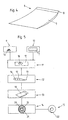
- FIG. 1 is a Cross section of a silencer housing 1 shown, in which a sieve tube 4 a damping material 2 is shown in a casing 3. The wrapping is sewn and shows the seam 5. In this state of assembly thus form Cavities and thus options for heat nests resulting in a short Service life or premature wear.
- the silencer insert oversize, the assembly is arranged in the casing 3 Damping material 2 around the sieve tube 4 by pushing it into the Silencer housing 1 problematic.
- the silencer insert can completely remove the housing 1 expand completely and the result is the state shown in FIG. 3.
- Fig. 4 shows an embodiment for a silencer insert in one Between production status.
- the silencer insert 6 has a mat shape and consists of a filled area 7, in which there is a loose in the envelope Containers made of individual elements made of a suitable sound absorbing material, for example fibers of textured E-glass yarn. That results in a protrusion 8 on one of the longitudinal edges.
- a predetermined amount of loose container 16 formed by sound absorption material is in one Step 10 .
- a blank 17 is formed from a wrapping material.
- the cut 17 is only a blank in the exemplary embodiment shown, but can be made from a There are a large number of individual cuts. Comes as wrapping material For example, a fabric made of textured E-glass gam in question.
- a process step 11 the loose container 16 is then on the blank 17 spread out and in process step 12 by folding over the envelope 17th a web with overhang 18 is formed.
- a web with overhang 18 is formed.
- the mat 19 is then wound around a mandrel 20 and into one by two form 21 of the pipe halves are embedded. Thus a Formed assembly element formed.
- gluing the supernatant 18 with the Wrapping material results in a cylindrical silencer insert 22 according to Method step 15.
- the silencer insert 22 can also be conical. This has a cylindrical or tubular shape and can be easily in an appropriate silencer housing. By Exposure to heat will adhere the supernatant 18 to the Dissolve the wrapping material and the mat spreads as desired and optimally inside in the housing.
Abstract
Description
Die vorliegende Erfindung betrifft ein Verfahren zur Herstellung von Schalldämpfereinsätzen für Schalldämpfer, welche ganz oder teilweise nach dem Absorptionsprinzip arbeiten, sowie nach dem Verfahren hergestellte Schalldämpfereinsätze.The present invention relates to a method for producing Muffler inserts for mufflers, all or part of which Absorption principle work, as well as manufactured according to the method Baffles.
Schalldämpfereinsätze der gattungsgemäßen Art werden in den Schalldämpfern der Auspuffanlagen von Verbrennungskraftmaschinen zur Geräuschdämpfung angeordnet. Üblicherweise handelt es sich bei den Schalldämpfern um topfartige Gebilde, durch welche das Auspuffrohr geführt ist, und in denen sich Schall ausbreiten und im Dämpfungsmaterial verlieren kann.Silencer inserts of the generic type are in the silencers the exhaust systems of internal combustion engines for noise reduction arranged. The silencers are usually pot-like Formations through which the exhaust pipe is guided and in which there is sound can spread and lose in the damping material.
Das schallschluckende Material ist vorzugsweise ein sogenannter poröser Schallschluckstoff, also ein Stoff ohne strukturierte Anordnungen von Hohlräumen und Materialverlauf.The sound-absorbing material is preferably a so-called porous Sound absorption material, i.e. a material without structured arrangements of cavities and material flow.
Solche Materialien müssen in die Schalldämpfertöpfe eingebracht werden. Es ist durchaus bekannt, diese Materialien wie eine Art Nachfüllpackung aus einem Behältnis herauszunehmen und in Schalldämpfertöpfe einzuschieben. Dies hat eine Reihe von Nachteilen, denn es läßt sich weder die einzubringende Menge genau festlegen und ein einheitlich lockeres Gemenge gewährleisten. Außerdem ist erwiesenermaßen die Standzeit derartiger Materialien äußerst gering.Such materials must be placed in the silencer pots. It is well known, these materials like a kind of refill from one Take out the container and insert it into silencer pots. this has a number of disadvantages, because the amount to be introduced cannot be define precisely and ensure a uniformly loose mixture. Moreover the service life of such materials has been proven to be extremely short.
Im DE G 89 10 785 wurde vorgeschlagen, ein aus innerem und äußerem Siebrohr mit verfülltem Zwischenraum gebildetes zylindrisches Schalldämpfereinsatz-Element auszubilden. Dies ist fertigungstechnisch, transport- und lagertechnisch sowie montagetechnisch aufwendig. Außerdem ergibt sich kein exakter Sitz im Schalldämpfertopf, so daß die Wirkung nicht befriedigend ist.In DE G 89 10 785 it was proposed to use an inner and outer sieve tube cylindrical silencer insert element formed with a filled space train. This is production technology, transport and storage technology as well as complex assembly. In addition, there is no exact fit in the Silencer pot, so that the effect is not satisfactory.
Aus der DE 36 42 714 A1 ist bekannt, eine Isolierung aus Faserformteilen in Form eines flexiblen Rohres auf Auspuffleitungen aufzuschieben. Dabei werden mehrere Lagen aus Metallfolie und Glasfaserschlauch zu einem Formteil zusammengesetzt.From DE 36 42 714 A1 it is known to form insulation from molded fiber parts to slide a flexible pipe onto exhaust pipes. Thereby several Layers of metal foil and glass fiber tube to form one molded part composed.
DE 31 44 193 offenbart einen schallapsorbierenden Körper aus einer Mineralfaserrohrschale. Dabei handelt es sich in erster Linie um gebundenes Material, also einen mit Bindemittel gebundenen Formkörper, dessen Wirkung unbefriedigend und dessen Standzeit kurz ist. Darüber hinaus sind Herstellung und Montage aufwendig und das Formteil ist kostenaufwendig.DE 31 44 193 discloses a sound-absorbing body made from a Mineral fiber pipe shell. In the first place it is bound Material, i.e. a molded article bound with a binding agent, its effect unsatisfactory and the service life is short. They are also manufacturing and assembly is complex and the molded part is expensive.
Aus dem DE G 91 01 926 ist bekannt, ein Dämpfstofformteil in Kissenform bereitzustellen. Dabei werden die Längsseiten vernäht, wodurch sich ein Materialschwund ergibt. Damit entsteht beim Anordnen des Kissens in einem Schalldämpfergehäuse ein Hohlraum, welcher zur Ausbildung von Hitzenestem führt. Diese führen zu vorzeitigem Verschleiß des Schalldämpfereinsatzes.From DE G 91 01 926 it is known to have a cushion shaped cushion part provide. The long sides are sewn, creating a Material loss results. This creates when arranging the pillow in one Muffler housing a cavity which is used to form heat nests leads. These lead to premature wear of the silencer insert.
Insgesamt haben die aus dem Stand der Technik bekannten Schalldämpfereinsätze den Nachteil, daß sie entweder schlecht dämpfende, steife und feste Körper sind, oder im Falle des Aufbaus als leichte Anhäufungen bei der Herstellung, der Montage und dem Einsatz problematisch sind. Insgesamt führen die aus dem Stand der Technik bekannten Einsätze zu einem häufigen Auswechselbedarf und sind somit unwirtschaftlich.Overall, those known from the prior art Silencer inserts have the disadvantage that they are either poorly damping, stiff and are solid, or in the case of construction as light accumulations in the Manufacturing, assembly and use are problematic. Overall lead the uses known from the prior art to a frequent Need for replacement and are therefore uneconomical.
Ausgehend vom vorgeschriebenen Stand der Technik liegt der vorliegenden Erfindung die Aufgabe zugrunde, ein Verfahren zur Herstellung von Schalldämpfereinsätzen sowie neuartige Schalldämpfereinsätze bereitzustellen, welche in Umfang und Gestalt dem Innenraum des zu füllenden Schalldämpfer-Gehäuses mit einfachen Mitteln möglichst optimal anpassbar sind, darüber hinaus wirtschaftlich herstellbar und in der Wirkung verbessert sind. Starting from the prescribed prior art, the present invention has for its object to provide a method for the manufacture of silencer inserts and novel silencer inserts, which can be adapted to the interior of the silencer housing to be filled with simple means as optimally as possible, and also economically producible and the effects are improved.
Zur technischen Lösung dieser Aufgabe wird verfahrensseitig vorgeschlagen, ein Verfahren zur Herstellung von Schalldämpfereinsätzen für Schalldämpfer, welche ganz oder teilweise nach dem Absorptionsprinzip arbeiten, wobei eine vorgegebene Menge eines losen Gebindes aus Einzelelementen eines geeigneten Schallschluckmaterials gebildet wird, das lose Gebinde von Zuschnitten aus einem flächigen Material zur Bildung eines Montage-Formelements umhüllt wird, das Montage-Formelement in eine der beabsichtigten Form des Schalldämpfereinsatzes entsprechenden Form zu einem Formverbund ausgeformt und fixiert wird, derart, daß die fixierte Form durch die Umhüllung ohne Auflösung in Einzelelemente bis zur Montage zum bestimmungsgemäßen Einsatz des Schalldämpfereinsatzes handhabbar ist, jedoch während des bestimmungsgemäßen Einsatzes als Schalldämpfereinsatz die Fixierung wenigstens teilweise wieder aufgehoben wird.For the technical solution to this problem, the process proposes a method for producing muffler inserts for mufflers, which work in whole or in part according to the absorption principle, a predetermined amount of a loose bundle being formed from individual elements of a suitable sound absorbing material, the loose bundle of blanks from a flat Material to form an assembly form element is encased, the assembly form element is shaped and fixed in a shape corresponding to the intended shape of the muffler insert, so that the fixed form through the encapsulation without dissolution in individual elements until assembly for intended use of the muffler insert is manageable, but the fixation is at least partially removed again during intended use as a muffler insert.
Gemäß dem erfindungsgemäßen Verfahren wird ein zwischenzeitlich bestehender Formverbund hergestellt, der das Produktionsverfahren abschließt und seinerseits gut lagerbar, transportierbar und montierbar ist. Im bestimmungsgemäßen Einsatz in einem Schalldämpfer-Gehäuse wird der Formverbund wieder teilweise aufgehoben, so daß eine optimale Ausfüllung des Innenraums des zu füllenden Schalldämpfergehäuses bewirkt wird. Darüber hinaus kommt der schalldämpfende Charakter des losen Gebindes optimal zur Wirkung.According to the method according to the invention, an existing one is created Molded composite that completes the production process and in turn is easy to store, transport and assemble. In the intended use in a silencer housing, the molded composite is again partial canceled so that an optimal filling of the interior of the to be filled Muffler housing is effected. In addition, there is the sound absorbing Character of the loose container optimally to the effect.
In vorteilhafter Weise wird der Formverbund aufgehoben durch die Einwirkung hoher Temperaturen. Die üblichen Betriebsbedingungen in Schalldämpfer-Gehäusen zeichnen sich durch sehr hohe Temperaturen aus. Diese können zur Auflösung von Klebeverbindungen, Nähten oder dergleichen führen und somit die wenigstens teilweise Auflösung des Formverbundes bewirken.Advantageously, the shape bond is canceled by the action high temperatures. The usual operating conditions in silencer housings are characterized by very high temperatures. These can be used Dissolve adhesive bonds, seams or the like and thus the cause at least partial dissolution of the composite.
Das lose Gebinde besteht in Form einer losen Häufung zur Verfügung, und zwar bindemittelfrei. In vorteilhafter Weise handelt es sich um einen Haufen von Faseranteilen aus texturiertem E-Glas-Garn. Auch Mineralwolle oder ähnliche Materialien können verwendet werden. Auch Mischungen aus verschiedenen Materialien sind einsetzbar. Das Bilden einer vorgegebenen Menge kann durch Wiegen erfolgen. The loose package is available in the form of a loose cluster, namely binder-free. Advantageously, it is a bunch of Fibers from textured E-glass yarn. Also mineral wool or the like Materials can be used. Mixtures of different ones Materials can be used. Forming a predetermined amount can by Weighing done.
Je nach gewünschtem Einsatzzweck, also zu füllenden Schalldämpfer-Gehäusetypen werden optimale Mengen bestimmbar sein . Diese können durch Gewicht oder sonstige meßbare physikalische Eigenschaften des Materials definiert werden. Das lose Gebinde wird dann zu einem Montage-Formelement ausgeformt und zu einem Formverbund fixiert. Eine Art zur Bildung des Formverbundes kann ein Vernähen sein, ein Umhüllen oder dergleichen. Gemäß einem Vorschlag der Erfindung können aus flächigen Materialien Zuschnitte gebildet werden, aus denen wiederum eine Umhüllung für die lose Häufung hergestellt wird. So kann das Material in die Umhüllung eingebracht und diese vernäht werden. Auch kann das Material nach Fertigstellung der Umhüllung in diese eingestopft werden. Abschließend wird die Umhüllung verschlossen und/oder ausgeformt. Eine Ausformung kann z.B. in der Bildung eines Schlauches bestehen, welche durch Bilden einer Rohrform aus der gefüllten Umhüllung und Kantenvernähung entsteht. Die Rohrformbildung kann dadurch unterstützt werden, daß die aus Umhüllung und umhülltem Schallschluckmaterial gebildete Matte um einen Dorn gewickelt wird. Die freien Kanten werden dann vernäht. Mit besonderem Vorteil hat sich hier erwiesen, daß an einer Kantenseite ein vernähbarer Überstand ausgebildet ist. Dieser Überstand kann beispielsweise glattflächig mit der nach dem Umwickeln anliegenden Außenseite der Matte verklebt werden. Zur Unterstützung der gewünschten Rohraußenform kann das um den Dorn gewickelte Formelement in ein Rohr eingebracht werden. Diese Rohrform entsteht vorzugsweise durch zusammenklappen zweier Rohrhälften. Nach dem Trocknen des Klebers hat das so gebildete Formelement die gewünschte Endform. Es läßt sich somit vom Dorn abziehen und gut transportieren und schließlich montieren. Durch die Hitzeeinwirkung im Einsatz wird sich zumindest die Klebenaht wieder auflösen und eine optimale Ausfüllung des Schalldämpfer-Gehäuses bewirken. Es können darüber hinaus auch weitere Nahtstellen beispielsweise durch Hitzeeinwirkung geöffnet werden, so daß eine noch bessere Ausfüllung und eine verbesserte Dämpferwirkung erzielt werden.Depending on the desired application, i.e. silencer housing types to be filled optimal quantities will be determinable. This can be done by Weight or other measurable physical properties of the material To be defined. The loose container then becomes an assembly form element molded and fixed to a form composite. A way to form the Compound can be sewing, wrapping or the like. According to A proposal of the invention can cut from flat materials are formed, from which in turn an envelope for the loose cluster will be produced. In this way, the material can be introduced into the casing and this to be sewn. The material can also be finished after the wrapping these are stuffed. Finally, the wrapper is closed and / or molded. A shape can e.g. in the formation of a hose exist, which by forming a tube shape from the filled casing and Edge stitching is created. Pipe shape formation can be supported by that the mat formed from wrapping and wrapped sound-absorbing material a mandrel is wound. The free edges are then sewn. With A particular advantage has been found here that one on one edge sewable supernatant is formed. This supernatant can, for example smooth with the outside of the mat after wrapping be glued. This can be used to support the desired outer tube shape molded element wound around the mandrel can be introduced into a tube. This Pipe shape is preferably created by folding two pipe halves together. After the adhesive has dried, the shaped element thus formed has the desired final shape. It can thus be pulled off the mandrel and well transport and finally assemble. Due to the heat in use will at least dissolve the adhesive seam and an optimal filling of the silencer housing. There can also be others Seams are opened for example by exposure to heat, so that a even better filling and an improved damping effect can be achieved.
Die Umhüllung kann beispielsweise ebenfalls aus texturiertem E-Glas-Garn, alternativen Materialien oder Mischungen bestehen. Auch können verschiedene Zuschnitte verschiedener Materialien je nach Einsatzzweck kombiniert werden.The wrapping can, for example, also be made of textured E-glass yarn, alternative materials or mixtures exist. Also can be different Blanks of different materials can be combined depending on the application.
Die Zuschnitte werden durch schneiden, prägen, stanzen oder auch durch gießen im Falle von Kunstoffverarbeitung gebildet. Als Kleber können handelsübliche Schmelzkleber verwendet werden. The blanks are cut, embossed, punched or poured formed in the case of plastic processing. Commercially available glue Hot melt adhesive can be used.
Zur Formverbundbildung können auch Netze, Vernähungen und dergleichen verwendet werden. Auch können Drahtgewebe eingesetzt werden. Wesentlich ist, daß die verwendeten Materialien unbrennbar sind. Auch sollen sie, soweit sie nicht bestimmungsgemäß aufzulösen sind, wie beispielsweise Nahtstellen oder Klebestellen, hitzebeständig sein, also nicht schmelzen. Desweiteren sollen sie entsprechende Hitzeisolierungseigenschaften aufweisen, um z.B. Carbongehäuse zu schützen bzw. Edelstahl vor dem Verfärben zu bewahren. Darüber hinaus sind nur Schallschluck- bzw. Schalldurchlässigkeitseigenschaften relevant.Nets, sewings and the like can also be used to form a composite be used. Wire mesh can also be used. It is essential that the materials used are non-flammable. They should also, unless they do are to be resolved as intended, such as seams or Glue points, be heat-resistant, so do not melt. Furthermore, they should have appropriate heat insulation properties, e.g. carbon housing to protect or to protect stainless steel from discoloration. Beyond that only sound absorption or sound transmission properties relevant.
Mit der Erfindung werden nach neuem Verfahren neuartige Schalldämpfereinsätze bereitgestellt, die verbesserte Schalldämpferwirkung haben, darüber hinaus wirtschaftlich herstellbar, einfach montierbar sowie eine große Standzeit haben.With the invention, novel silencer inserts are made using a new method provided that have improved silencing effect, in addition economical to manufacture, easy to assemble and have a long service life.
Vorrichtungsseitig wird die Aufgabe gelöst durch einen neuartigen Schalldämpfereinsatz, gebildet aus einer vorgegebenen Menge eines losen Gebindes aus Einzelelementen eines geeigneten Schallschluckmaterials, umhüllt zu einem Montage-Formelement mit Zuschnitten aus einem flächigen Material, wobei das Montage-Formelement entsprechend der beabsichtigten Form des Schalldämpfereinsatzes zu einem Formverbund geformt und formfixiert ist, derart, daß die Form durch die Umhüllung ohne Auflösung in Einzelelemente bis zur Montage zum bestimmungsgemäßen Einsatz des Schalldämpfereinsatzes handhabbar ist, jedoch während des bestimmungsgemäßen Einsatzes als Schalldämpfereinsatz die Fixierung wenigstens teilweise wieder aufhebbar ist.On the device side, the task is solved by a new type Muffler insert, formed from a predetermined amount of a loose Package encased in individual elements of a suitable sound absorbing material to an assembly form element with cuts from a flat material, the mounting form element corresponding to the intended shape of the Muffler insert is shaped and fixed in shape, such that that the shape through the wrapping without dissolution in individual elements up to Installation for the intended use of the silencer insert is manageable, but during the intended use as Muffler insert the fixation can be at least partially removed.
Weitere Vorteile und Merkmale der Erfindung ergeben sich aus der folgenden Beschreibung anhand der Figuren. Dabei zeigen:
- Fig. 1
- eine schematische Schnittansicht eines Schalldämpfergehäuses mit eingesetztem Schalldämpfereinsatz im Montagezustand;
- Fig. 2
- eine alternative
Ausführungsform zu Figur 1 in Überdimensionierung; - Fig. 3
- ein Ausführungsbeispiel der Erfindung nach fertiger Montage;
- Fig. 4
- ein Ausführungsbeispiel für einen erfindungsgemäßen Schalldämpfereinsatz und
- Fig. 5
- eine flußdiagrammartige Darstellung des Herstellungsverfahrens.
- Fig. 1
- a schematic sectional view of a silencer housing with inserted silencer insert in the assembled state;
- Fig. 2
- an alternative embodiment to Figure 1 in oversizing;
- Fig. 3
- an embodiment of the invention after assembly;
- Fig. 4
- an embodiment of a silencer insert according to the invention and
- Fig. 5
- a flowchart-like representation of the manufacturing process.
Sofern aus einem mit schalldämpfermaterial gefüllten Kissen eine Rohrform durch
Wickeln und Kantenvernähen gebildet ist, bildet sich eine Naht. In Fig. 1 ist ein
Querschnitt eines Schalldämpfergehäuses 1 gezeigt, in welchem ein Siebrohr 4
umgebend ein Dämpfstoff 2 in einer Umhüllung 3 gezeigt ist. Die Umhüllung ist
vernäht und zeigt die Naht 5. In diesem Montagezustand bilden sich somit
Hohlräume und damit Optionen für Hitzenester mit der Folge einer kurzen
Standzeit beziehungsweise einem vorzeitigen Verschleiß.If a pipe shape is made from a cushion filled with silencer material
A winding is formed and edge sewing is formed. 1 is a
Cross section of a
Würde man, wie in Fig. 2 angedeutet, den Schalldämpfereinsatz
überdimensionieren, ist die Montage des in der Umhüllung 3 angeordneten
Dämpfstoffes 2 um das Siebrohr 4 durch Einschieben in das
Schalldämpfergehäuse 1 problematisch.Would, as indicated in Fig. 2, the silencer insert
oversize, the assembly is arranged in the
Nimmt man jedoch ein wie in Fig. 1 gezeigtes Formelement, bei welchem unter
Hitzeeinwirkung die Fixierung, also beispielsweise die Naht 5, wenigstens teilweise
wieder auflöst, so kann sich der Schalldämpfer-Einsatz das Gehäuse 1 vollständig
ausfüllend ausdehnen und es ergibt sich der in Fig. 3 gezeigte Zustand.However, if one takes a shaped element as shown in FIG. 1, in which under
Heat fixation, for example the
Fig. 4 zeigt ein Ausführungsbeispiel für einen Schalldämpfereinsatz in einem
Zwischenfertigungszustand. Der Schalldämpfereinsatz 6 hat eine Mattenform und
besteht aus einem gefüllten Bereich 7, in dem sich in der Umhüllung ein loses
Gebinde aus Einzelelementen aus einem geeigneten Schallschluckmaterial,
beispielsweise Fasern texturierten E-Glas-Garnes, befindet. Durch die ergibt sich
ein Überstand 8 an einer der Längskanten.Fig. 4 shows an embodiment for a silencer insert in one
Between production status. The silencer insert 6 has a mat shape and
consists of a filled area 7, in which there is a loose in the envelope
Containers made of individual elements made of a suitable sound absorbing material,
for example fibers of textured E-glass yarn. That results in
a
Zur Herstellung eines solchen Elementes und zur weiteren Verarbeitung wird
gemäß Fig. 5 zunächst in einem ersten Schritt 9 eine vorgegebenen Menge eines
losen Gebindes 16 von Schallschluckmaterial gebildet. Parallel wird in einem
Schritt 10 ein Zuschnitt 17 aus einem Umhüllungsmaterial gebildet. Der Zuschnitt
17 ist im gezeigten Ausführungsbeispiel nur ein Zuschnitt, kann aber aus einer
Vielzahl von Einzelzuschnitten bestehen. Als Umhüllungsmaterial kommt
beispielsweise ein Gewebe aus texturiertem E-Glas-Gam in Frage.For the production of such an element and for
In einem Verfahrensschritt 11 wird dann das lose Gebinde 16 auf dem Zuschnitt
17 ausgebreitet und im Verfahrensschritt 12 durch Umfalten der Umhüllung 17
eine Bahn mit Überstand 18 gebildet. Durch Vernähen der Kanten wird nun ein
Element 19 mit Überstand gebildet, Verfahrensschritt 13, welches dem in Fig. 4
gezeigten Element entspricht. In a
Die Matte 19 wird dann um einen Wickeldorn 20 gewickelt und in eine durch zwei
aufeinanderklappbare Rohrhälften gebildete Form 21 eingebettet. Somit wird ein
Montage-Formelement gebildet. Durch verkleben des Überstands 18 mit dem
Umhüllungsmaterial ergibt sich ein zylindrischer Schalldämpfereinsatz 22 gemäß
Verfahrensschritt 15. Alternativ hierzu kann der Schalldämpfereinsatz 22 auch
konisch ausgebildet sein. Dieser hat Zylinder- oder Rohrform und kann leicht in
einem entsprechenden Schalldämpfer-Gehäuse montiert werden. Durch
Hitzeeinwirkung wird sich die Verklebung des Überstands 18 mit dem
Umhüllungsmaterial auflösen und die Matte breitet sich wunschgemäß und optimal
im Inneren anliegend im Gehäuse aus.The
Die beschriebenen Ausführungsbeispiele dienen der Erläuterung und sind nicht beschränkend. Insbesondere können die Materialien, Formen und dergleichen variiert werden. The exemplary embodiments described serve for explanation and are not limiting. In particular, the materials, shapes and the like can be varied.
- 11
- Schalldämpfergehäusemuffler housing
- 22
- DämpfstoffDämpfstoff
- 33
- Umhüllungwrapping
- 44
- Siebrohrperforated pipe
- 55
- Nahtseam
- 66
- Einsatz-ElementUse element
- 77
- Umhüllungwrapping
- 88th
- ÜberstandGot over
- 99
- Mengenbildungset construction
- 1010
- Zuschnittcut
- 1111
- Aufbringungapplication
- 1212
- Einlagerungwarehousing
- 1313
- Verschließungsealing
- 1414
- Formgebungshape
- 1515
- FormelementbildungForm element formation
- 1616
- loses Gemengeloose batch
- 1717
- Zuschnittcut
- 1818
- Vorformpreform
- 1919
- Montage-FormelememtMounting Formelememt
- 2020
- Wickeldornmandrel
- 2121
- Rohrgehäusetube housing
- 2222
- Formverbundform composite
Claims (14)
- Method for producing silencer inserts for silencers which operate entirely or partly on the absorption principle, a predetermined amount of a loose skein (16) of individual elements of a suitable sound-absorbent material being formed, the loose skein (16) being sheathed by cut-to-size pieces (10, 17) of a sheet-like material to form an installation form element (19), the installation form element (19) being shaped into a form corresponding to the intended form of the silencer insert, to give a composite form unit (22), and fixed in such a way that the fixed form can be handled, as a result of the sheathing, without breaking up into individual elements until the silencer insert is installed for the intended use but the fixing is at least partially released again during the intended use as a silencer insert.
- Method according to Claim 1, characterized in that the release of the composite form unit (22) takes place by thermal exposure.
- Method according to one of the preceding claims, characterized in that the composite form unit (22) is of a tubular design.
- Method according to one of the preceding claims, characterized in that the loose skein (16) is formed without any binder.
- Method according to one of the preceding claims, characterized in that at least partially textured low-alkali glass yarn is used as the sound-absorbent material.
- Method according to one of the preceding claims, characterized in that the sound-absorbent material at least partially comprises mineral wool.
- Method according to one of the preceding claims, characterized in that the loose skein (16) is weighed for the forming of a predetermined amount (9).
- Method according to Claim 7, characterized in that sheet-like material which at least partially consists of textured low-alkali glass yarn is used.
- Method according to one of the preceding claims, characterized in that the fixing is performed at least partially by sewing.
- Method according to one of the preceding claims, characterized in that the fixing is performed at least partially by adhesive bonding.
- Method according to one of the preceding claims, characterized in that the installation form element (19) is wound around a mandrel for the forming of a tubular composite form unit (22).
- Method according to Claim 11, characterized in that the installation form element (19) is introduced into a tube.
- Silencer insert, produced by at least one of the methods 1 to 12, formed from a predetermined amount of a loose skein (16) of individual elements of a suitable sound-absorbent material, sheathed with cut-to-size pieces (10, 17) of a sheet-like material to form an installation form element (19), the installation form element being shaped in a way corresponding to the intended form of the silencer insert, to give a composite form unit, and form-fixed in such a way that the form can be handled, as a result of the sheathing, without breaking up into individual elements until the silencer insert is installed for the intended use but the fixing can be at least partially released again during the intended use as a silencer insert.
- Silencer insert according to Claim 13, characterized in that the composite form unit (22) forming the silencer insert is released by heat exposure.
Priority Applications (1)
| Application Number | Priority Date | Filing Date | Title |
|---|---|---|---|
| SI9930099T SI0953736T1 (en) | 1998-05-01 | 1999-04-24 | Insert for a silencer and method for producing it |
Applications Claiming Priority (2)
| Application Number | Priority Date | Filing Date | Title |
|---|---|---|---|
| DE29807858U DE29807858U1 (en) | 1998-05-01 | 1998-05-01 | Silencer inserts made of textured glass yarn |
| DE29807858U | 1998-05-01 |
Publications (3)
| Publication Number | Publication Date |
|---|---|
| EP0953736A2 EP0953736A2 (en) | 1999-11-03 |
| EP0953736A3 EP0953736A3 (en) | 2000-01-19 |
| EP0953736B1 true EP0953736B1 (en) | 2002-06-12 |
Family
ID=8056543
Family Applications (1)
| Application Number | Title | Priority Date | Filing Date |
|---|---|---|---|
| EP99108115A Expired - Lifetime EP0953736B1 (en) | 1998-05-01 | 1999-04-24 | Insert for a silencer and method for producing it |
Country Status (7)
| Country | Link |
|---|---|
| US (1) | US6241043B1 (en) |
| EP (1) | EP0953736B1 (en) |
| JP (1) | JPH11324642A (en) |
| AT (1) | ATE219209T1 (en) |
| DE (2) | DE29807858U1 (en) |
| ES (1) | ES2178316T3 (en) |
| SI (1) | SI0953736T1 (en) |
Families Citing this family (13)
| Publication number | Priority date | Publication date | Assignee | Title |
|---|---|---|---|---|
| EP1010869A1 (en) | 1998-12-18 | 2000-06-21 | h.k.o. Isolier- und Textiltechnik Gesellschaft mit beschränkter Haftung | Sound insulation insert for a silencer, silencer and method of manufactoring the same |
| US6585078B2 (en) * | 2000-12-22 | 2003-07-01 | Race Tools, Inc. | Muffler insert |
| US6446750B1 (en) | 2001-03-16 | 2002-09-10 | Owens Corning Fiberglas Technology, Inc. | Process for filling a muffler shell with fibrous material |
| US6581723B2 (en) | 2001-08-31 | 2003-06-24 | Owens Corning Composites Sprl | Muffler shell filling process, muffler filled with fibrous material and vacuum filling device |
| DE20218251U1 (en) * | 2002-11-25 | 2003-01-30 | G & H Schallschutz Gmbh | Sound absorption device |
| US20060037815A1 (en) * | 2004-08-18 | 2006-02-23 | Schabel Norman G Jr | Particulate insulation materials |
| ITRM20050107A1 (en) * | 2005-03-10 | 2006-09-11 | Vale S R L | MATTER MADE ENTIRELY IN FIBERGLASS. |
| US8590155B2 (en) * | 2009-06-03 | 2013-11-26 | Ocv Intellectual Capital, Llc | Apparatus for and process of filling a muffler with fibrous material utilizing a directional jet |
| US8336673B2 (en) * | 2010-07-07 | 2012-12-25 | Bay Industries Inc. | Muffler, muffler insert, and methods and apparatus for making |
| DE102011012156A1 (en) | 2011-02-23 | 2012-08-23 | Dbw Holding Gmbh | Process for the preparation of a molding material made of fiber materials and apparatus therefor |
| DE102011012202B4 (en) | 2011-02-23 | 2014-09-25 | Dbw Holding Gmbh | Silencer insert for motor vehicles and method for the manufacture thereof |
| DE202014006987U1 (en) * | 2014-09-01 | 2015-09-03 | Reinz-Dichtungs-Gmbh | Heat shield and shielded with such a heat shield component |
| US9938872B2 (en) | 2015-06-09 | 2018-04-10 | Bay Fabrication, Inc. | Muffler insert, and systems, methods and apparatus for making |
Citations (3)
| Publication number | Priority date | Publication date | Assignee | Title |
|---|---|---|---|---|
| DE3205186A1 (en) * | 1982-02-13 | 1983-08-25 | Wilfried 6238 Hofheim Seitz | Method for producing a silencing filling for an exhaust silencer |
| DE3827863A1 (en) * | 1988-08-17 | 1990-02-22 | Leistritz Ag | Catalytic exhaust gas purification apparatus |
| EP0692616A1 (en) * | 1994-07-15 | 1996-01-17 | Owens-Corning Fiberglas Corporation | Preformed sound-absorbing material for engine exhaust muffler |
Family Cites Families (14)
| Publication number | Priority date | Publication date | Assignee | Title |
|---|---|---|---|---|
| US1627324A (en) * | 1925-06-12 | 1927-05-03 | Internat Silencer Company 1926 | Silencer for gaseous currents |
| JPS5428952A (en) * | 1977-08-09 | 1979-03-03 | Toyota Motor Corp | Silencer for internal combustion engine |
| US4316523A (en) * | 1980-06-04 | 1982-02-23 | Boretti Napoleon P | Silencer for gas discharge devices |
| DE3144193A1 (en) | 1981-11-06 | 1983-05-19 | Grünzweig + Hartmann und Glasfaser AG, 6700 Ludwigshafen | Sound-absorbing body, in particular for installation in silencers |
| DE3642714A1 (en) | 1986-12-13 | 1988-06-16 | Witzenmann Metallschlauchfab | Exhaust pipe for internal combustion engines |
| US4947957A (en) * | 1989-06-16 | 1990-08-14 | Multiform Desiccants, Inc. | Regenerable desiccant cartridge for automotive muffler |
| DE8910785U1 (en) | 1989-09-09 | 1989-12-07 | Goertz, Johannes, 4054 Nettetal, De | |
| US5007499A (en) * | 1990-02-23 | 1991-04-16 | Carrier Corporation | Silencer for a centrifugal compressor |
| DE9101926U1 (en) | 1991-02-19 | 1991-05-23 | Goertz, Johannes, 4054 Nettetal, De | |
| US5593745A (en) | 1994-02-24 | 1997-01-14 | Caterpillar Inc. | Insulated port liner assembly |
| JP2967390B2 (en) * | 1994-04-21 | 1999-10-25 | 本田技研工業株式会社 | Muffler and manufacturing method thereof |
| JP2719890B2 (en) * | 1994-09-16 | 1998-02-25 | 株式会社ユタカ技研 | Silencer |
| US5777947A (en) * | 1995-03-27 | 1998-07-07 | Georgia Tech Research Corporation | Apparatuses and methods for sound absorption using hollow beads loosely contained in an enclosure |
| US6053276A (en) * | 1998-06-09 | 2000-04-25 | D'amico, Jr.; John | Muffler packing method with injection of cartrided continuous filament fiberglass |
-
1998
- 1998-05-01 DE DE29807858U patent/DE29807858U1/en not_active Expired - Lifetime
-
1999
- 1999-04-24 AT AT99108115T patent/ATE219209T1/en active
- 1999-04-24 EP EP99108115A patent/EP0953736B1/en not_active Expired - Lifetime
- 1999-04-24 ES ES99108115T patent/ES2178316T3/en not_active Expired - Lifetime
- 1999-04-24 DE DE59901701T patent/DE59901701D1/en not_active Expired - Lifetime
- 1999-04-24 SI SI9930099T patent/SI0953736T1/en unknown
- 1999-04-26 JP JP11117562A patent/JPH11324642A/en active Pending
- 1999-04-30 US US09/303,255 patent/US6241043B1/en not_active Expired - Fee Related
Patent Citations (3)
| Publication number | Priority date | Publication date | Assignee | Title |
|---|---|---|---|---|
| DE3205186A1 (en) * | 1982-02-13 | 1983-08-25 | Wilfried 6238 Hofheim Seitz | Method for producing a silencing filling for an exhaust silencer |
| DE3827863A1 (en) * | 1988-08-17 | 1990-02-22 | Leistritz Ag | Catalytic exhaust gas purification apparatus |
| EP0692616A1 (en) * | 1994-07-15 | 1996-01-17 | Owens-Corning Fiberglas Corporation | Preformed sound-absorbing material for engine exhaust muffler |
Also Published As
| Publication number | Publication date |
|---|---|
| ATE219209T1 (en) | 2002-06-15 |
| DE59901701D1 (en) | 2002-07-18 |
| SI0953736T1 (en) | 2002-12-31 |
| JPH11324642A (en) | 1999-11-26 |
| DE29807858U1 (en) | 1998-08-27 |
| EP0953736A3 (en) | 2000-01-19 |
| ES2178316T3 (en) | 2002-12-16 |
| EP0953736A2 (en) | 1999-11-03 |
| US6241043B1 (en) | 2001-06-05 |
Similar Documents
| Publication | Publication Date | Title |
|---|---|---|
| EP0953736B1 (en) | Insert for a silencer and method for producing it | |
| DE602004006986T2 (en) | MANUFACTURING METHOD FOR MINERALWOOD PIPE COATINGS | |
| EP0353761B1 (en) | Exhaust gas noise muffler | |
| DE10200668B4 (en) | Engine muffler and method of making the same | |
| EP2678535B1 (en) | Method for producing a molded material from fiber materials, and device for this purpose | |
| EP3700366B1 (en) | Biodegradable segment of a smoking product | |
| DE102009002536A1 (en) | Fiber product, fiber molding and method for producing the same | |
| DE102007010814A1 (en) | Silencer insulation element, silencer and method for producing a silencer | |
| DE665167C (en) | Absorbent material for silencers | |
| DE3205185A1 (en) | Process for producing a sound-absorbing filling for a silencer as well as sound-absorbing filling produced by this process | |
| EP2678534B1 (en) | Muffler insert for motor vehicles and method for producing same | |
| DE102010012416A1 (en) | Component for use as e.g. support material or protective material for e.g. glass or mineral fibers for installation of motor car, has layers made of steel wool, where steel fibers of wool are welded with one another for solidification | |
| WO2008119670A1 (en) | Component comprising functional fibers, and method for the production thereof | |
| DE3304809A1 (en) | MOLDED PART FROM BINDER-PROVIDED MINERAL FIBERS FOR SOUND-ABSORBING COVERING A PERFORATED EXHAUST PIPE, AND METHOD FOR THE PRODUCTION THEREOF | |
| DE10031154A1 (en) | Soot filter used in diesel engines comprises hollow cylindrical filter insert consisting of threads and/or yarn formed from silicon dioxide endless fibers | |
| WO2014044698A1 (en) | Bag for insertion into a cavity of a silencer, which cavity is intended for sound damping | |
| DE3614921A1 (en) | Process for producing an annular wreath core, and wreath core produced according to this process | |
| AT412700B (en) | Production of multilayer strip-shaped molded part, comprises manufacturing a groove-shaped recess in an inner surface of a cover layer of the molded part by material ablation method as grinding, milling, rubbing and eroding | |
| EP1143055A2 (en) | Moldable stitchweave composite | |
| EP1010869A1 (en) | Sound insulation insert for a silencer, silencer and method of manufactoring the same | |
| DE3732700A1 (en) | Silencer for exhaust systems in motor vehicles | |
| DE102013020872A1 (en) | Fiber-reinforced plastic component with a hollow structure | |
| DE20218618U1 (en) | Sound damping sleeve for silencers of motorcycles and automobiles consists of textured mineral multi-layered coiled endless fibers and uniformly distributed organic binding material, hardened by thermal process | |
| AT208528B (en) | Multi-layer mold for the precision casting process | |
| DE102012018371A1 (en) | Bag for insertion into cavity of certain sound attenuation silencer, has casing that is provided with glass fibers, and deadening or absorbing filling that is passed through sheath is injected into interior of bag |
Legal Events
| Date | Code | Title | Description |
|---|---|---|---|
| PUAI | Public reference made under article 153(3) epc to a published international application that has entered the european phase |
Free format text: ORIGINAL CODE: 0009012 |
|
| AK | Designated contracting states |
Kind code of ref document: A2 Designated state(s): AT BE CH DE ES FR GB IT LI NL |
|
| AX | Request for extension of the european patent |
Free format text: AL;LT;LV;MK;RO;SI |
|
| PUAL | Search report despatched |
Free format text: ORIGINAL CODE: 0009013 |
|
| AK | Designated contracting states |
Kind code of ref document: A3 Designated state(s): AT BE CH CY DE DK ES FI FR GB GR IE IT LI LU MC NL PT SE |
|
| AX | Request for extension of the european patent |
Free format text: AL;LT;LV;MK;RO;SI |
|
| 17P | Request for examination filed |
Effective date: 20000119 |
|
| 17Q | First examination report despatched |
Effective date: 20000412 |
|
| AKX | Designation fees paid |
Free format text: AT BE CH DE ES FR GB IT LI NL |
|
| AXX | Extension fees paid |
Free format text: SI PAYMENT 20000115 |
|
| GRAG | Despatch of communication of intention to grant |
Free format text: ORIGINAL CODE: EPIDOS AGRA |
|
| GRAG | Despatch of communication of intention to grant |
Free format text: ORIGINAL CODE: EPIDOS AGRA |
|
| GRAH | Despatch of communication of intention to grant a patent |
Free format text: ORIGINAL CODE: EPIDOS IGRA |
|
| GRAH | Despatch of communication of intention to grant a patent |
Free format text: ORIGINAL CODE: EPIDOS IGRA |
|
| GRAA | (expected) grant |
Free format text: ORIGINAL CODE: 0009210 |
|
| AK | Designated contracting states |
Kind code of ref document: B1 Designated state(s): AT BE CH DE ES FR GB IT LI NL |
|
| AX | Request for extension of the european patent |
Free format text: SI PAYMENT 20000115 |
|
| REF | Corresponds to: |
Ref document number: 219209 Country of ref document: AT Date of ref document: 20020615 Kind code of ref document: T |
|
| REG | Reference to a national code |
Ref country code: GB Ref legal event code: FG4D Free format text: NOT ENGLISH |
|
| REG | Reference to a national code |
Ref country code: CH Ref legal event code: EP |
|
| REF | Corresponds to: |
Ref document number: 59901701 Country of ref document: DE Date of ref document: 20020718 |
|
| REG | Reference to a national code |
Ref country code: CH Ref legal event code: NV Representative=s name: E. BLUM & CO. PATENTANWAELTE |
|
| GBT | Gb: translation of ep patent filed (gb section 77(6)(a)/1977) |
Effective date: 20020721 |
|
| ET | Fr: translation filed | ||
| REG | Reference to a national code |
Ref country code: ES Ref legal event code: FG2A Ref document number: 2178316 Country of ref document: ES Kind code of ref document: T3 |
|
| PLBE | No opposition filed within time limit |
Free format text: ORIGINAL CODE: 0009261 |
|
| STAA | Information on the status of an ep patent application or granted ep patent |
Free format text: STATUS: NO OPPOSITION FILED WITHIN TIME LIMIT |
|
| PG25 | Lapsed in a contracting state [announced via postgrant information from national office to epo] |
Ref country code: LI Free format text: LAPSE BECAUSE OF NON-PAYMENT OF DUE FEES Effective date: 20030430 Ref country code: CH Free format text: LAPSE BECAUSE OF NON-PAYMENT OF DUE FEES Effective date: 20030430 |
|
| 26N | No opposition filed |
Effective date: 20030313 |
|
| REG | Reference to a national code |
Ref country code: CH Ref legal event code: PL |
|
| REG | Reference to a national code |
Ref country code: SI Ref legal event code: IF |
|
| PGFP | Annual fee paid to national office [announced via postgrant information from national office to epo] |
Ref country code: DE Payment date: 20110414 Year of fee payment: 13 Ref country code: FR Payment date: 20110510 Year of fee payment: 13 Ref country code: ES Payment date: 20110426 Year of fee payment: 13 |
|
| PGFP | Annual fee paid to national office [announced via postgrant information from national office to epo] |
Ref country code: NL Payment date: 20110426 Year of fee payment: 13 Ref country code: AT Payment date: 20110414 Year of fee payment: 13 Ref country code: GB Payment date: 20110421 Year of fee payment: 13 Ref country code: BE Payment date: 20110414 Year of fee payment: 13 |
|
| PGFP | Annual fee paid to national office [announced via postgrant information from national office to epo] |
Ref country code: IT Payment date: 20110422 Year of fee payment: 13 |
|
| BERE | Be: lapsed |
Owner name: *GOERTZ JOHANNES ULRICH Effective date: 20120430 |
|
| REG | Reference to a national code |
Ref country code: NL Ref legal event code: V1 Effective date: 20121101 |
|
| REG | Reference to a national code |
Ref country code: AT Ref legal event code: MM01 Ref document number: 219209 Country of ref document: AT Kind code of ref document: T Effective date: 20120424 |
|
| GBPC | Gb: european patent ceased through non-payment of renewal fee |
Effective date: 20120424 |
|
| REG | Reference to a national code |
Ref country code: FR Ref legal event code: ST Effective date: 20121228 |
|
| PG25 | Lapsed in a contracting state [announced via postgrant information from national office to epo] |
Ref country code: GB Free format text: LAPSE BECAUSE OF NON-PAYMENT OF DUE FEES Effective date: 20120424 Ref country code: AT Free format text: LAPSE BECAUSE OF NON-PAYMENT OF DUE FEES Effective date: 20120424 Ref country code: BE Free format text: LAPSE BECAUSE OF NON-PAYMENT OF DUE FEES Effective date: 20120430 |
|
| REG | Reference to a national code |
Ref country code: DE Ref legal event code: R119 Ref document number: 59901701 Country of ref document: DE Effective date: 20121101 |
|
| PG25 | Lapsed in a contracting state [announced via postgrant information from national office to epo] |
Ref country code: FR Free format text: LAPSE BECAUSE OF NON-PAYMENT OF DUE FEES Effective date: 20120430 Ref country code: IT Free format text: LAPSE BECAUSE OF NON-PAYMENT OF DUE FEES Effective date: 20120424 |
|
| REG | Reference to a national code |
Ref country code: SI Ref legal event code: KO00 Effective date: 20130128 |
|
| PG25 | Lapsed in a contracting state [announced via postgrant information from national office to epo] |
Ref country code: NL Free format text: LAPSE BECAUSE OF NON-PAYMENT OF DUE FEES Effective date: 20121101 |
|
| REG | Reference to a national code |
Ref country code: ES Ref legal event code: FD2A Effective date: 20130716 |
|
| PG25 | Lapsed in a contracting state [announced via postgrant information from national office to epo] |
Ref country code: ES Free format text: LAPSE BECAUSE OF NON-PAYMENT OF DUE FEES Effective date: 20120425 |
|
| PG25 | Lapsed in a contracting state [announced via postgrant information from national office to epo] |
Ref country code: DE Free format text: LAPSE BECAUSE OF NON-PAYMENT OF DUE FEES Effective date: 20121101 |