EP0953481A2 - Coussin gonflable constitué de plusieurs panneaux - Google Patents
Coussin gonflable constitué de plusieurs panneaux Download PDFInfo
- Publication number
- EP0953481A2 EP0953481A2 EP99107439A EP99107439A EP0953481A2 EP 0953481 A2 EP0953481 A2 EP 0953481A2 EP 99107439 A EP99107439 A EP 99107439A EP 99107439 A EP99107439 A EP 99107439A EP 0953481 A2 EP0953481 A2 EP 0953481A2
- Authority
- EP
- European Patent Office
- Prior art keywords
- panel section
- body panel
- boundary edge
- substantially straight
- center panel
- Prior art date
- Legal status (The legal status is an assumption and is not a legal conclusion. Google has not performed a legal analysis and makes no representation as to the accuracy of the status listed.)
- Granted
Links
Images


Classifications
-
- B—PERFORMING OPERATIONS; TRANSPORTING
- B60—VEHICLES IN GENERAL
- B60R—VEHICLES, VEHICLE FITTINGS, OR VEHICLE PARTS, NOT OTHERWISE PROVIDED FOR
- B60R21/00—Arrangements or fittings on vehicles for protecting or preventing injuries to occupants or pedestrians in case of accidents or other traffic risks
- B60R21/02—Occupant safety arrangements or fittings, e.g. crash pads
- B60R21/16—Inflatable occupant restraints or confinements designed to inflate upon impact or impending impact, e.g. air bags
- B60R21/23—Inflatable members
- B60R21/231—Inflatable members characterised by their shape, construction or spatial configuration
Definitions
- the present invention relates to inflatable protective cushions, and provides a cushion construction particularly useful in the frontal or side protection of occupants in a transportation vehicle, such as an automotive vehicle, railroad, car, airplane or the like.
- a process for forming the cushion according to the present invention is also provided.
- Inflatable protective cushions used in passenger vehicles are a component of relatively complex passive restraint systems.
- the main elements of these systems are: an impact sensing system, an ignition system, a propellant material, an attachment device, a system enclosure, and an inflatable protective cushion.
- the propellant Upon sensing an impact, the propellant is ignited causing an explosive release of gases filing the cushion to a deployed state which can absorb the impact of the forward movement of a body and dissipate its energy by means of rapid venting of the gas.
- the entire sequence of events occurs within about 30 milliseconds.
- the cushion In the un-deployed state, the cushion is stored in or near the steering column, the dashboard, in a door, or in the back of a front seat placing the cushion in close proximity to the person or object it is to protect.
- Inflatable cushion systems commonly referred to as air bag systems have been used in the past to protect both the operator of the vehicle and passengers.
- Systems for the protection of the vehicle operator have typically been mounted in the steering column of the vehicle and have utilized cushion constructions directly deployable towards the driver.
- These driver-side cushions are typically of a relatively simple configuration in that they function over a fairly small well-defined area between the driver and the steering column.
- One such configuration is disclosed in U.S. Patent 5,533,755 to Nelsen et al., issued July 9, 1996, the teachings of which are incorporated herein by reference.
- Inflatable cushions for use in the protection of passengers against frontal or side impacts must generally have a more complex configuration since the position of a vehicle passenger may not be well defined and greater distance may exist between the passenger and the surface of the vehicle against which that passenger might be thrown in the event of a collision.
- Prior cushions for use in such environments are disclosed in U.S. Patent 5,520,416 to Bishop, issued May 28, 1996; U. S. Patent 5,454,594 to Krickl issued October 3, 1995; U.S. Patent 5,423,273 to Hawthorn et al. issued June 13, 1995; U.S. Patent 5,316,337 to Yamaji et al. issued May 31, 1994; U.S. Patent 5,310,216 to Wehner et al. issued May 10, 1994; U.S.
- the permeability of the cushion structure is an important factor in determining the rate of inflation and subsequent rapid deflation following the impact event.
- the use of several fabric panels in construction of the cushion may prove to be a useful design feature.
- the use of multiple fabric panels in the cushion structure also permits the development of relatively complex three dimensional geometries which may be of benefit in the formation of cushions for passenger side applications wherein a full bodied cushion is desired. While the use of multiple fabric panels provides several advantages in terms of permeability manipulation and geometric design, the use of multiple fabric panels for use in passenger side restraint cushions has historically required the assembly of panels having multiple different geometries involving multiple curved seams.
- an important consideration in cutting panel structures from a base material is the ability to maximize the number of panels which can be cut from a fixed area through close-packed nesting of the panels. It has been found that minimizing the number of different geometries making up panels in the cushion and using geometries with substantially straight line perimeter configurations generally permits an enhanced number of panels to be cut from the base material.
- the use of panels having generally straight line profiles has the added benefit of permitting the panels to be attached to one another using substantially straight seams or be substantially formed during the weaving process using a jacquard or dobby loom.
- the present invention provides a passenger side airbag configuration which may be constructed from two body panel sections of substantially similar multiple straight sided geometry and one quadrilateral center panel section.
- the body panel sections are connected to one another and to the center panel section by a series of flat, straight seams.
- the airbag configuration formed according to the present invention results in highly efficient utilization of materials and may be constructed substantially without the need for complex curved seaming operations. As such, the present invention constitutes a useful advancement over the present art.
- Another object of the invention is to provide a method of making a low cost inflatable protective cushion of simple and structurally efficient design
- the present invention provides an airbag cushion for use in a vehicle restraint system, which in the most preferred embodiment includes two body panel sections of substantially similar geometry joined to one another by two substantially straight seams along corresponding lateral boundary edges.
- the boundary segments of the body panels which are not joined to one another are joined around the perimeter of a quadrilateral center panel by a series of substantially straight seams thereby forming an inflatable cushion structure.
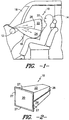
- FIG. 1 there is shown an inflatable restraint cushion 10 for use with an inflator 12 to protect a vehicle occupant 14 from impacting against a dash panel 16, windshield 18 or other interior surface in the event of a collision.
- the inflatable restraint cushion 10 includes a frontal impact center panel 20 and two body panel sections 22, 24 which are connected to and extend away from the frontal impact center panel to establish fluid communication with the inflator 12.
- FIG. 2 there is illustrated a potentially preferred seaming arrangement for use in establishing the connective relationship between the frontal impact center panel 20 and the body panel sections 22, 24.
- the body panel sections 22, 24 are connected to one another by means of a substantially straight body seam 26. While only one such body seam 26 is illustrated in FIG. 2 it is to be understood that in the preferred embodiment an identical seam is likewise disposed along the length of the body panel sections 22, 24 on the opposite side of the restraint cushion 10.
- the frontal impact panel 20 is preferably joined to the non-seamed edges of the body panel sections 22, 24 by means of a series of substantially straight face seams 27 as shown.
- the inflatable restraint cushion 10 is preferably turned inside out so as to place the seams on the interior thereof during an inflation event. Moreover, while the assembly configuration as shown in FIG.2 has a relatively straight line box-like configuration, once the cushion 10 is turned inside out and inflated, the profile tends to assume the generally desirable rounded profile as illustrated in FIG. 1.
- seams or seaming operations include not only traditional sewn seams but also by way of example only and not limitation, interwoven seams, adhesive seams, melt bonded seams, ultrasonic seams, and other suitable attachment methods as may be known to those of skill in the art.
- interwoven seams such as interwoven seams, adhesive seams, melt bonded seams, ultrasonic seams, and other suitable attachment methods as may be known to those of skill in the art.
- adhesive seams such as may be known to those of skill in the art.
- melt bonded seams such as may be known to those of skill in the art.
- ultrasonic seams such as may be known to those of skill in the art.
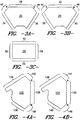
- each of the body panel sections 22, 24 is generally of a diamond shape including a substantially straight upper boundary edge 28, 30 bounded by a first terminal end "A" and a second terminal end "B".
- Each of the body panel sections 22,24 also preferably includes a first substantially straight lateral boundary edge 34, 38 and a second substantially straight lateral boundary edge 36, 40.
- Each of the body panel sections 22, 24 also preferably includes a first substantially straight intermediate boundary edge 42, 44 extending between the first terminal end of the upper boundary edge 28, 30 and the first lateral boundary edge 34, 38 as shown.
- a second substantially straight intermediate boundary edge 46, 48 preferably connects the second terminal end of the upper boundary edge 28, 30 of each body panel section to the second lateral boundary edge 36, 40 thereof.
- the frontal impact center panel 20 is preferably of a rectilinear geometry including four substantially straight boundary edges 52, 54, 56, 58 as shown.
- the impact center panel 20 is preferably of a square or rectangular geometry having substantially right angels between intersecting boundary edges. It is contemplated that a non-square elongate geometry having a length dimension which is substantially greater than the width dimension may be utilized.
- the length dimension would preferably be at least ten percent greater that the width dimension, would more preferably be at least 20 percent greater than the width dimension, and would most preferably be at least 30 percent greater than the width dimension, although it is to be understood that such length dimension may be substantially greater than these identifiable minimums and may, in fact be many times the width dimension if a substantial area is to be covered.
- the materials of construction from which the frontal impact center panel 20 and each body panel section 22, 24 are formed may be either similar or dissimilar from one another.
- Each of these panels may be formed from a number of materials including by way of example only and not limitation woven fabrics, knitted fabrics, non-woven fabrics, films and combinations thereof.
- Woven fabrics may be preferred with woven fabrics formed of tightly woven construction such as plain or panama weave constructions being particularly preferred.
- Such woven fabrics may be formed from yarns of polyester, polyamides such as nylon 6 and nylon-6,6 or other suitable material as may be known to those in the skill in the art.
- Multifilament yarns having a relatively low denier per filament rating of not greater than about 1-4 denier per filament may be desirable for bags requiring particular good foldability.
- the cushion is to be formed by sewing together precut panel sections 20, 22, 24 from a base material and a woven fabric is utilized for a frontal impact center panel 20 such panel is preferably cut from the fabric such that its boundary edges are disposed substantially parallel to the warp and fill directions.
- woven fabric is utilized to form the body panel sections 22, 24 such panels are preferably cut such that the upper boundary edges 28, 30 run substantially parallel to either the warp or the fill directions.
- woven fabrics formed from synthetic yarns having linear densities of about 40 denier to about 1200 denier are believed to be useful in the formation of the cushion 10 according to the present invention.
- Fabrics formed from yarns having linear densities of about 315 to about 840 are believed to be particularly useful, and fabrics formed from yarns having linear densities in the range of about 400 to about 650 are believed to be most useful.
- each of the panels 20, 22, 24 may be formed of the same material, the panels may also be formed from differing materials and or constructions.
- one or both of the body panel sections 22, 24 may be formed from an uncoated relatively high permeability fabric having an air permeability of about 5 CFM per square foot or higher while the center panel 20 is formed from a coated or uncoated fabric having an air permeability of about 3 CFM per square foot or less when measured at a differential pressure of 0.5 inches of water across the fabric.
- Fabrics having permeabilities of about 1-3 CFM per square foot may be desirable in either the body panels or center panel section.
- Fabrics having permeabilities below 2 CFM and preferably below 1 CFM in the uncoated state may be preferred.
- Such fabrics which have permeabilities below 2 CFM which permeability does not substantially increase by more than a factor of about 2 when the fabric is subjected to biaxial stresses in the range of up to about 100 pounds force may be particularly preferred.
- Fabrics which exhibit such characteristics which are formed by means of fluid jet weaving may be most preferred.
- neoprene, silicone urethanes or disperse polyamides may be preferred.
- Coatings such as dispersed polyamides having dry add on weights of about 0.6 ounces per square yard or less and more preferably about 0.4 ounces per square yard or less and most preferably about 0.3 per square yard or less may be particularly preferred so as to minimize fabric weight and enhance foldability. It is, of course, to be understood that aside from the use of coatings, different characteristics in various panels may also be achieved through the use of fabrics incorporating differing weave densities and/or finishing treatments such as calendering as may be known to those in the skill of the art.
- restraint cushion 10 has been illustrated and is described herein in terms of the principal panel sections 20, 22, 24, it is to be understood that such cushion 10 may also include additional components such as shape defining tethers, gas vents, mouth reinforcements, and the like as may be known to those in the skill of the art.
- substantially straight body seams 26 are applied along corresponding lateral boundary edges 34, 38 and 36, 40.
- the frontal impact center panel 20 is seamed along two opposing boundary edges 52, 54 to the substantially straight upper boundary edges 28, 30 of the body panel sections 22, 24.
- the intermediate boundary edges 42, 44, 46, 48 are seamed along the remaining boundary edges 56, 58 of the center panel 20 so as to form an enclosed structure.
- the total perimeter length of the center panel 20 is substantially equal to the combined lengths of the upper boundary edges 34, 38 and intermediate boundary edges 42, 44, 46, 48 of the body panel sections.
- the upper and lower boundary edges 52, 54 of the center panel will be of substantially equal length to the upper boundary edges 36, 40 of the body panel sections while the first substantially straight intermediate boundary edges 42, 44 of the body panel sections have a combined length which is substantially equal to the length of the first lateral boundary edge 56 of the center panel with the combined lengths of the second substantially straight intermediate boundary edges 46, 48 of the body panel sections being substantially equivalent to the length of the second center panel lateral boundary edge 58.
- the preferred geometry permits formation of an enclosed cushion by means of a series of fiat, straight seaming operations to form the body seams 26 and face seams 27 as illustrated in FIG. 2.
- Such flat, straight seaming operations greatly enhance the efficiency of the manufacturing process.
- each of the face seams 27 will fall along the primary yam directions in the center panel 20 thereby lending added stability to the frontal impact area of the cushion.
- FIGS. 4A-4C there is illustrated a frontal impact center panel 120 and corresponding body panel sections 122, 124 for use in formation of a cushion which has a deep arcuate expanded profile such as may be desirable for surrounding a dash panel in a top mount configuration. That is, where the cushion is deployed from the top of the dash panel rather than from a position directly opposing the occupant.
- the construction and assembly of the restraint cushion incorporating the panel sections as illustrated in FIGS. 4A-4C is substantially identical to the description provided above in relation to FIGS. 3A-3C.
- the mouth-forming opening is arranged so as to accommodate an inflator in a top mount configuration.
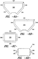
- FIGS. 5A-5C there is illustrated a frontal impact center panel 220 and corresponding body panel sections 222, 224 useful in applications requiring a cushion having an elongated profile.
- such application may include full frontal impact protection or side impact protection for an occupant's head and torso.
- the body panel sections 222, 224 are characterized by upper boundary edges 228, 230 of substantial length and a center panel 220 having corresponding substantial length dimension along its upper and lower and boundary edges 252, 254. As will be noted, this length dimension is more that two times the width as measured along the lateral boundary edges 256, 258.
- first lateral boundary edges 234, 238 are joined together; corresponding second lateral boundary edges 236, 240 are joined together; upper and lower center panel boundary edges 252, 254 are joined to the upper boundary edges 228, 230 of the body panel sections; first intermediate boundary edges 242, 244 of the body panel sections are joined along a first lateral boundary edge 256 of the center panel and the second lateral boundary edges 246 248 of the body panel sections are joined along the remaining lateral boundary edge 258 of the center panel 220.
- the resultant elongated cushion structure may be divided into individual lobes or chambers through the application of inflation limiting seams or tethers.
- the incorporation of such lobes may be desirable to protect different sections of the body which behave in differing manners during an impact event.
- an upper lobe may be used to protect the head and torso while lower lobe may be used to protect the knee.
- One potentially preferred seaming configuration to develop such lobes is disclosed in my pending application 08/969,823 the contents of which are incorporated herein by reference.
- FIGS. 6A-6D there is illustrated yet another embodiment of the present invention which includes a rectilinear center panel 320 and two body panel sections 322, 324.
- the body panel sections of this embodiment are characterized by a relatively long, substantially straight upper boundary edge 328, 330 and intermediate boundary edges 342, 344, 346, 348 which are disposed at substantially right angles to such upper boundary edges.
- the cushion assembly of this embodiment differs slightly from that of previous embodiments in that the body panel sections 322, 324 are seamed together along the corresponding lateral boundary edges 334, 338 and 336, 340 as well as along corresponding intermediate boundary edges 342, 344 and 346, 348 in order to enclose the cushion structure 310.
- the upper boundary edges 328, 330 of the body panel sections are wrapped around and seamed to the perimeter of the center panel 20. Accordingly, the upper boundary edge 328 of the first body panel section 322 is of a length sufficient to span the upper boundary edge 352 of the center panel as well as one half of each lateral edge thereof. In like fashion, the upper boundary edge 330 of the second body panel section is of sufficient length to wrap around the remaining perimeter of the center panel 320.
- the present invention also contemplates so called "on-loom" cushion formation.
- Such formation preferably involves the use of a jacquard or dobby loom as are well known to those of skill in the art.
- these looms permit the formation and attachment of multiple layers of fabric in a single operation.
- these machines can be programmed to adjust the weave density or cover factor of different sections of the fabric.
- the cushion according to the present invention may be either partially or completely formed on such weaving machines thereby substantially reducing or eliminating subsequent sewing operations.
- a mouth opening is permitted to remain in the region below the terminus of the lateral boundary edges.
- such mouth openings are mated to the inflator 12 either with or without additional reinforcement layer.
- FIG. 7A there is illustrated a body panel section 422 similar to previously described body panel sections 22, 24 but having a nonsymmetrical double peaked mouth configuration including a first peak 462, and a second peak 464.
- the inflator 12 is housed between such peaks either with or without additional mouth reinforcements.
- FIG. 7B Another potentially preferred mouth configuration is illustrated in FIG. 7B wherein there is illustrated a body panel section 522 similar to body panel sections 22,24 but including a mouth-forming configuration of two angled tab portions 566, 568 on each panel section. These tab portions may be disposed around the inflator which is housed in the depression formed therebetween following cushion formation as described above.
- each body panel section 622 terminates at its lower portion with a box tab 672 as shown.
- box tabs may be used to surround the inflator in a simple and efficient manner.
Landscapes
- Engineering & Computer Science (AREA)
- Mechanical Engineering (AREA)
- Air Bags (AREA)
Applications Claiming Priority (2)
| Application Number | Priority Date | Filing Date | Title |
|---|---|---|---|
| US09/070,428 US6019390A (en) | 1998-04-30 | 1998-04-30 | Multiple panel airbag |
| US70428 | 1998-04-30 |
Publications (3)
| Publication Number | Publication Date |
|---|---|
| EP0953481A2 true EP0953481A2 (fr) | 1999-11-03 |
| EP0953481A3 EP0953481A3 (fr) | 2002-03-27 |
| EP0953481B1 EP0953481B1 (fr) | 2004-02-25 |
Family
ID=22095234
Family Applications (1)
| Application Number | Title | Priority Date | Filing Date |
|---|---|---|---|
| EP99107439A Expired - Lifetime EP0953481B1 (fr) | 1998-04-30 | 1999-04-27 | Coussin gonflable constitué de plusieurs panneaux |
Country Status (5)
| Country | Link |
|---|---|
| US (1) | US6019390A (fr) |
| EP (1) | EP0953481B1 (fr) |
| JP (1) | JPH11334509A (fr) |
| DE (1) | DE69914963T2 (fr) |
| ES (1) | ES2214763T3 (fr) |
Cited By (4)
| Publication number | Priority date | Publication date | Assignee | Title |
|---|---|---|---|---|
| WO2002016174A1 (fr) * | 2000-08-18 | 2002-02-28 | Milliken & Company | Coussin de securite gonflable a panneaux multiples et procede de production associe |
| WO2002018180A3 (fr) * | 2000-08-30 | 2003-02-06 | Milliken & Co | Tissus resistant a l'abrasion et/ou a la perforation, coussins gonflables de securite et procedes |
| EP1698523A3 (fr) * | 2000-08-30 | 2008-04-02 | Milliken & Company | Tissus résistant à l'abraison et/ ou à la perforation, coussins gonflables de sécurité et procédés |
| WO2008116574A1 (fr) * | 2007-03-26 | 2008-10-02 | Autoliv Development Ab | Airbag et procédé de fabrication associé |
Families Citing this family (35)
| Publication number | Priority date | Publication date | Assignee | Title |
|---|---|---|---|---|
| JP3740890B2 (ja) * | 1998-05-08 | 2006-02-01 | タカタ株式会社 | エアバッグ及びエアバッグ装置 |
| US6299204B1 (en) * | 1998-08-18 | 2001-10-09 | Milliken & Company | Vehicle restraint system comprising an airbag having an integrated mouth |
| DE29814990U1 (de) * | 1998-08-20 | 1998-12-17 | Trw Repa Gmbh | Gassack |
| DE19903361A1 (de) * | 1999-01-28 | 2000-08-03 | Breed Automotive Tech | Verfahren zur Herstellung eines Luftsackes und Luftsack |
| US6220309B1 (en) | 1999-09-24 | 2001-04-24 | Milliken & Company | Inflatable fabrics comprising basket-woven attachment points between fabric panels |
| US6364356B1 (en) * | 1999-09-24 | 2002-04-02 | Milliken & Company | Airbag cushion comprising sewn reinforcement seams |
| US6467563B1 (en) * | 2000-06-19 | 2002-10-22 | Delphi Technologies, Inc. | Windshield frame air bag for pedestrian protection |
| US7004499B1 (en) * | 2000-07-20 | 2006-02-28 | Cadence Innovation Llc | Occupant protection system for vehicle with air bag |
| US6672618B2 (en) | 2000-10-17 | 2004-01-06 | Milliken & Company | Multiple panel airbag and method |
| US6805374B2 (en) | 2001-02-08 | 2004-10-19 | Autoliv Asp, Inc. | Inflatable curtain cushion |
| US6554316B2 (en) | 2001-03-08 | 2003-04-29 | Autoliv Asp, Inc. | Multi-chamber airbag gas venting system |
| KR100909909B1 (ko) * | 2001-10-09 | 2009-07-29 | 콜린스 앤 아이크만 코포레이션 | 가소성 외피 형성방법 및 장치 |
| US7550103B2 (en) | 2001-10-09 | 2009-06-23 | International Automotive Components Group North America, Inc. | Plastic skin forming process |
| US6712169B2 (en) | 2002-05-16 | 2004-03-30 | Delphi Technologies, Inc. | Displaceable automotive hood assembly |
| FR2848165B1 (fr) * | 2002-12-05 | 2005-03-04 | Faurecia Ind | Ensemble d'equipement comprenant une structure gonflable et un organe frangible de fixation, et vehicule automobile correspondant |
| FR2848166B1 (fr) * | 2002-12-05 | 2006-01-06 | Faurecia Ind | Ensemble d'equipement comprenant une structure gonflable et des moyens de guidage de son deploiement et vehicule automobile correspondant |
| US7152877B2 (en) * | 2003-01-24 | 2006-12-26 | Takata Corporation | Airbag and airbag apparatus |
| US7121584B2 (en) * | 2003-01-24 | 2006-10-17 | Takata Corporation | Airbag and airbag apparatus |
| US20050098993A1 (en) * | 2003-11-07 | 2005-05-12 | Takata Corporation | Airbag device |
| US7264268B2 (en) * | 2005-02-18 | 2007-09-04 | Tk Holdings Inc. | Air bag |
| US7255367B2 (en) * | 2005-02-18 | 2007-08-14 | Tk Holdings Inc. | Air bag |
| US7243947B2 (en) * | 2005-02-18 | 2007-07-17 | Tk Holdings Inc. | Air bag |
| US20060237957A1 (en) * | 2005-04-22 | 2006-10-26 | Takata Restraint Systems, Inc. | Sealed cushion |
| CA2649406C (fr) * | 2006-04-12 | 2012-06-26 | Norbert Huber | Tissu pour coussin gonflable de securite |
| JP2008114721A (ja) * | 2006-11-06 | 2008-05-22 | Autoliv Development Ab | エアバッグ装置 |
| JP5016429B2 (ja) * | 2007-09-25 | 2012-09-05 | 日本プラスト株式会社 | エアバッグおよびエアバッグの製造方法 |
| DE102008026365B4 (de) | 2008-06-02 | 2010-11-18 | International Automotive Components Group Gmbh | Vorrichtung und Verfahren zur Herstellung von Slush-Häuten |
| US7950688B2 (en) * | 2008-09-17 | 2011-05-31 | Tk Holdings Inc. | Airbag module |
| DE102009040118A1 (de) * | 2009-09-04 | 2011-03-10 | Autoliv Development Ab | Beifahrer-Frontgassack und Kraftfahrzeug |
| JP5523780B2 (ja) * | 2009-09-14 | 2014-06-18 | 日本プラスト株式会社 | 助手席用エアバッグ |
| DE102014107847A1 (de) | 2014-06-04 | 2015-12-17 | Eschmann Textures International Gmbh | Formwerkzeug für die Herstellung eines Kunststoffkörpers aus einem thermoplastischen Kunststoffmaterial |
| US10829082B2 (en) | 2018-01-31 | 2020-11-10 | Nissan North America, Inc. | Airbag device |
| JP7192617B2 (ja) * | 2019-03-29 | 2022-12-20 | 豊田合成株式会社 | エアバッグ |
| US10967829B1 (en) | 2019-09-17 | 2021-04-06 | Joyson Safety Systems Acquisition Llc | Driver side airbag module |
| KR20240027032A (ko) * | 2021-06-30 | 2024-02-29 | 아우토리브 디벨롭먼트 아베 | 차량용 에어백 장치 |
Citations (20)
| Publication number | Priority date | Publication date | Assignee | Title |
|---|---|---|---|---|
| US3792873A (en) | 1971-02-05 | 1974-02-19 | Uniroyal Ag | Passive restraint system for vehicle occupants |
| US4921735A (en) | 1987-11-03 | 1990-05-01 | Klaus Bloch | Air bag for motor vehicles |
| US4944529A (en) | 1985-12-14 | 1990-07-31 | Audi Ag. | Inflatable protective cushion |
| US5087071A (en) | 1990-08-01 | 1992-02-11 | Trw Vehicle Safety Systems Inc. | Vehicle air bag structure and method of forming |
| US5090729A (en) | 1989-12-15 | 1992-02-25 | Takata Corporation | Air bag for a passenger |
| US5093163A (en) | 1989-09-07 | 1992-03-03 | Akzo N.V. | Uncoated fabric for airbags |
| US5110666A (en) | 1991-05-06 | 1992-05-05 | Reeves Brothers, Inc. | Coated fabric structure for air bag applications |
| US5236775A (en) | 1990-02-12 | 1993-08-17 | Hoechst Aktiengesellschaft | Fabric for airbag |
| US5277230A (en) | 1993-02-22 | 1994-01-11 | Milliken Research Corporation | Double twillwoven air bag fabric |
| US5310216A (en) | 1992-10-30 | 1994-05-10 | Alliedsignal Inc. | Flat sew pattern passenger air bag |
| US5316337A (en) | 1992-03-30 | 1994-05-31 | Toyo Tire & Rubber Co., Ltd. | Inflatable bags for airbag passive restraint systems for front seat passenger and methods for manufacturing thereof |
| US5356680A (en) | 1991-07-16 | 1994-10-18 | Akzo N.V. | Industrial fabrics of controlled air permeability and high ageing resistance and manufacture thereof |
| US5423273A (en) | 1994-02-01 | 1995-06-13 | General Motors Corporation | Single seam cube shaped restraint cushion |
| US5454594A (en) | 1993-04-30 | 1995-10-03 | Trw Repa Gmbh | Inflatable gas bag for vehicle occupant restraining systems |
| US5477890A (en) | 1993-07-31 | 1995-12-26 | Akzo Nobel Nv | Integrated weaving and wet treatment method for manufacturing uncoated industrial woven fabrics |
| US5503197A (en) | 1994-03-30 | 1996-04-02 | Milliken Research Corporation | Method for producing high weave density airbag fabric on a water-jet loom using unsized yarns |
| US5508073A (en) | 1991-02-26 | 1996-04-16 | Akzo Nv | Uncoated fabric for manufacturing air bags |
| US5520416A (en) | 1994-10-03 | 1996-05-28 | Ford Motor Company | Power tilt, telescoping and internally collapsible steering column |
| US5533755A (en) | 1993-06-28 | 1996-07-09 | Sandia Corp./Precision Fabrics Grp., Inc. | Structurally efficient inflatable protective device |
| US5704402A (en) | 1996-04-01 | 1998-01-06 | Milliken Research Corporation | Air bag fabric |
Family Cites Families (5)
| Publication number | Priority date | Publication date | Assignee | Title |
|---|---|---|---|---|
| US3799578A (en) * | 1970-09-24 | 1974-03-26 | Nissan Motor | Vehicle safety device |
| US3810654A (en) * | 1972-05-05 | 1974-05-14 | Gen Motors Corp | Occupant restraint cushion assembly and method of manufacture |
| DE2224827A1 (de) * | 1972-05-20 | 1973-11-29 | Hoffman Rheem Maschinen Gmbh | Herstellung von luftsaecken fuer kraftfahrzeuge |
| US5456493A (en) * | 1994-06-10 | 1995-10-10 | Morton International, Inc. | Cylindrical air bag |
| US5520414A (en) * | 1994-11-23 | 1996-05-28 | Milliken Research Corporation | Inflatable restraint cushion |
-
1998
- 1998-04-30 US US09/070,428 patent/US6019390A/en not_active Expired - Lifetime
-
1999
- 1999-04-27 ES ES99107439T patent/ES2214763T3/es not_active Expired - Lifetime
- 1999-04-27 EP EP99107439A patent/EP0953481B1/fr not_active Expired - Lifetime
- 1999-04-27 DE DE69914963T patent/DE69914963T2/de not_active Expired - Lifetime
- 1999-04-30 JP JP11124188A patent/JPH11334509A/ja not_active Withdrawn
Patent Citations (20)
| Publication number | Priority date | Publication date | Assignee | Title |
|---|---|---|---|---|
| US3792873A (en) | 1971-02-05 | 1974-02-19 | Uniroyal Ag | Passive restraint system for vehicle occupants |
| US4944529A (en) | 1985-12-14 | 1990-07-31 | Audi Ag. | Inflatable protective cushion |
| US4921735A (en) | 1987-11-03 | 1990-05-01 | Klaus Bloch | Air bag for motor vehicles |
| US5093163A (en) | 1989-09-07 | 1992-03-03 | Akzo N.V. | Uncoated fabric for airbags |
| US5090729A (en) | 1989-12-15 | 1992-02-25 | Takata Corporation | Air bag for a passenger |
| US5236775A (en) | 1990-02-12 | 1993-08-17 | Hoechst Aktiengesellschaft | Fabric for airbag |
| US5087071A (en) | 1990-08-01 | 1992-02-11 | Trw Vehicle Safety Systems Inc. | Vehicle air bag structure and method of forming |
| US5508073A (en) | 1991-02-26 | 1996-04-16 | Akzo Nv | Uncoated fabric for manufacturing air bags |
| US5110666A (en) | 1991-05-06 | 1992-05-05 | Reeves Brothers, Inc. | Coated fabric structure for air bag applications |
| US5356680A (en) | 1991-07-16 | 1994-10-18 | Akzo N.V. | Industrial fabrics of controlled air permeability and high ageing resistance and manufacture thereof |
| US5316337A (en) | 1992-03-30 | 1994-05-31 | Toyo Tire & Rubber Co., Ltd. | Inflatable bags for airbag passive restraint systems for front seat passenger and methods for manufacturing thereof |
| US5310216A (en) | 1992-10-30 | 1994-05-10 | Alliedsignal Inc. | Flat sew pattern passenger air bag |
| US5277230A (en) | 1993-02-22 | 1994-01-11 | Milliken Research Corporation | Double twillwoven air bag fabric |
| US5454594A (en) | 1993-04-30 | 1995-10-03 | Trw Repa Gmbh | Inflatable gas bag for vehicle occupant restraining systems |
| US5533755A (en) | 1993-06-28 | 1996-07-09 | Sandia Corp./Precision Fabrics Grp., Inc. | Structurally efficient inflatable protective device |
| US5477890A (en) | 1993-07-31 | 1995-12-26 | Akzo Nobel Nv | Integrated weaving and wet treatment method for manufacturing uncoated industrial woven fabrics |
| US5423273A (en) | 1994-02-01 | 1995-06-13 | General Motors Corporation | Single seam cube shaped restraint cushion |
| US5503197A (en) | 1994-03-30 | 1996-04-02 | Milliken Research Corporation | Method for producing high weave density airbag fabric on a water-jet loom using unsized yarns |
| US5520416A (en) | 1994-10-03 | 1996-05-28 | Ford Motor Company | Power tilt, telescoping and internally collapsible steering column |
| US5704402A (en) | 1996-04-01 | 1998-01-06 | Milliken Research Corporation | Air bag fabric |
Cited By (8)
| Publication number | Priority date | Publication date | Assignee | Title |
|---|---|---|---|---|
| WO2002016174A1 (fr) * | 2000-08-18 | 2002-02-28 | Milliken & Company | Coussin de securite gonflable a panneaux multiples et procede de production associe |
| US6837517B2 (en) | 2000-08-18 | 2005-01-04 | Milliken & Company | Multiple panel airbag and method |
| US7048304B1 (en) | 2000-08-18 | 2006-05-23 | Milliken & Company | Multiple panel airbag and method |
| CN100340430C (zh) * | 2000-08-18 | 2007-10-03 | 美利肯公司 | 多镶片安全气囊及其制造方法 |
| WO2002018180A3 (fr) * | 2000-08-30 | 2003-02-06 | Milliken & Co | Tissus resistant a l'abrasion et/ou a la perforation, coussins gonflables de securite et procedes |
| EP1698523A3 (fr) * | 2000-08-30 | 2008-04-02 | Milliken & Company | Tissus résistant à l'abraison et/ ou à la perforation, coussins gonflables de sécurité et procédés |
| US7686331B2 (en) | 2000-08-30 | 2010-03-30 | Milliken & Company | Fabrics, airbags and methods |
| WO2008116574A1 (fr) * | 2007-03-26 | 2008-10-02 | Autoliv Development Ab | Airbag et procédé de fabrication associé |
Also Published As
| Publication number | Publication date |
|---|---|
| DE69914963T2 (de) | 2004-12-16 |
| US6019390A (en) | 2000-02-01 |
| EP0953481B1 (fr) | 2004-02-25 |
| DE69914963D1 (de) | 2004-04-01 |
| JPH11334509A (ja) | 1999-12-07 |
| ES2214763T3 (es) | 2004-09-16 |
| EP0953481A3 (fr) | 2002-03-27 |
Similar Documents
| Publication | Publication Date | Title |
|---|---|---|
| US6019390A (en) | Multiple panel airbag | |
| US6672618B2 (en) | Multiple panel airbag and method | |
| US6837517B2 (en) | Multiple panel airbag and method | |
| US6299205B1 (en) | Vehicle restraint system comprising an airbag having a looped pocket for inflation canister disposition | |
| US6086095A (en) | Airbag cushion exhibiting low seam and fabric usage and simultaneously high available inflation volume | |
| US7261927B2 (en) | Structurally efficient airbag cushion exhibiting low seam usage and simultaneously high available inflation volume | |
| US6375219B2 (en) | Airbag cushion exhibiting low fabric usage and simultaneously high available inflation volume | |
| US20020041086A1 (en) | Three-dimensional passenger airbag and method | |
| EP1097063A1 (fr) | Systeme de retenue pour vehicule avec coussin d'air a poche integree | |
| EP1149740A2 (fr) | Coussin de sécurité alliant une faible utilisation de matériau à un volume de gonflage important |
Legal Events
| Date | Code | Title | Description |
|---|---|---|---|
| PUAI | Public reference made under article 153(3) epc to a published international application that has entered the european phase |
Free format text: ORIGINAL CODE: 0009012 |
|
| AK | Designated contracting states |
Kind code of ref document: A2 Designated state(s): AT BE CH CY DE DK ES FI FR GB GR IE IT LI LU MC NL PT SE Kind code of ref document: A2 Designated state(s): DE ES FR GB IT SE |
|
| AX | Request for extension of the european patent |
Free format text: AL;LT;LV;MK;RO;SI |
|
| PUAL | Search report despatched |
Free format text: ORIGINAL CODE: 0009013 |
|
| AK | Designated contracting states |
Kind code of ref document: A3 Designated state(s): AT BE CH CY DE DK ES FI FR GB GR IE IT LI LU MC NL PT SE |
|
| AX | Request for extension of the european patent |
Free format text: AL;LT;LV;MK;RO;SI |
|
| 17P | Request for examination filed |
Effective date: 20020508 |
|
| AKX | Designation fees paid |
Free format text: DE ES FR GB IT SE |
|
| GRAP | Despatch of communication of intention to grant a patent |
Free format text: ORIGINAL CODE: EPIDOSNIGR1 |
|
| GRAS | Grant fee paid |
Free format text: ORIGINAL CODE: EPIDOSNIGR3 |
|
| GRAA | (expected) grant |
Free format text: ORIGINAL CODE: 0009210 |
|
| AK | Designated contracting states |
Kind code of ref document: B1 Designated state(s): DE ES FR GB IT SE |
|
| REG | Reference to a national code |
Ref country code: GB Ref legal event code: FG4D |
|
| REG | Reference to a national code |
Ref country code: IE Ref legal event code: FG4D |
|
| REF | Corresponds to: |
Ref document number: 69914963 Country of ref document: DE Date of ref document: 20040401 Kind code of ref document: P |
|
| REG | Reference to a national code |
Ref country code: SE Ref legal event code: TRGR |
|
| REG | Reference to a national code |
Ref country code: ES Ref legal event code: FG2A Ref document number: 2214763 Country of ref document: ES Kind code of ref document: T3 |
|
| ET | Fr: translation filed | ||
| PLBE | No opposition filed within time limit |
Free format text: ORIGINAL CODE: 0009261 |
|
| STAA | Information on the status of an ep patent application or granted ep patent |
Free format text: STATUS: NO OPPOSITION FILED WITHIN TIME LIMIT |
|
| REG | Reference to a national code |
Ref country code: IE Ref legal event code: MM4A |
|
| 26N | No opposition filed |
Effective date: 20041126 |
|
| PGFP | Annual fee paid to national office [announced via postgrant information from national office to epo] |
Ref country code: SE Payment date: 20060426 Year of fee payment: 8 Ref country code: ES Payment date: 20060426 Year of fee payment: 8 |
|
| PGFP | Annual fee paid to national office [announced via postgrant information from national office to epo] |
Ref country code: IT Payment date: 20070519 Year of fee payment: 9 |
|
| PG25 | Lapsed in a contracting state [announced via postgrant information from national office to epo] |
Ref country code: SE Free format text: LAPSE BECAUSE OF NON-PAYMENT OF DUE FEES Effective date: 20070428 |
|
| REG | Reference to a national code |
Ref country code: ES Ref legal event code: FD2A Effective date: 20070428 |
|
| PG25 | Lapsed in a contracting state [announced via postgrant information from national office to epo] |
Ref country code: ES Free format text: LAPSE BECAUSE OF NON-PAYMENT OF DUE FEES Effective date: 20070428 |
|
| PG25 | Lapsed in a contracting state [announced via postgrant information from national office to epo] |
Ref country code: IT Free format text: LAPSE BECAUSE OF NON-PAYMENT OF DUE FEES Effective date: 20080427 |
|
| PGFP | Annual fee paid to national office [announced via postgrant information from national office to epo] |
Ref country code: FR Payment date: 20110504 Year of fee payment: 13 |
|
| PGFP | Annual fee paid to national office [announced via postgrant information from national office to epo] |
Ref country code: GB Payment date: 20110426 Year of fee payment: 13 |
|
| REG | Reference to a national code |
Ref country code: DE Ref legal event code: R082 Ref document number: 69914963 Country of ref document: DE Representative=s name: FRANK WACKER SCHOEN PATENTANWAELTE, DE |
|
| REG | Reference to a national code |
Ref country code: DE Ref legal event code: R082 Ref document number: 69914963 Country of ref document: DE Representative=s name: FRANK WACKER SCHOEN PATENTANWAELTE, DE |
|
| REG | Reference to a national code |
Ref country code: DE Ref legal event code: R082 Ref document number: 69914963 Country of ref document: DE Representative=s name: FRANK WACKER SCHOEN PATENTANWAELTE, DE Effective date: 20121001 Ref country code: DE Ref legal event code: R082 Ref document number: 69914963 Country of ref document: DE Representative=s name: FRANK WACKER SCHOEN PATENTANWAELTE, DE Effective date: 20120720 Ref country code: DE Ref legal event code: R081 Ref document number: 69914963 Country of ref document: DE Owner name: AUTOLIV ASP, INC., OGDEN, US Free format text: FORMER OWNER: MILLIKEN & CO., SPARTANBURG, S.C., US Effective date: 20121001 Ref country code: DE Ref legal event code: R081 Ref document number: 69914963 Country of ref document: DE Owner name: AUTOLIV ASP, INC., US Free format text: FORMER OWNER: MILLIKEN & CO., SPARTANBURG, US Effective date: 20121001 |
|
| GBPC | Gb: european patent ceased through non-payment of renewal fee |
Effective date: 20120427 |
|
| REG | Reference to a national code |
Ref country code: FR Ref legal event code: ST Effective date: 20121228 |
|
| PG25 | Lapsed in a contracting state [announced via postgrant information from national office to epo] |
Ref country code: GB Free format text: LAPSE BECAUSE OF NON-PAYMENT OF DUE FEES Effective date: 20120427 |
|
| PG25 | Lapsed in a contracting state [announced via postgrant information from national office to epo] |
Ref country code: FR Free format text: LAPSE BECAUSE OF NON-PAYMENT OF DUE FEES Effective date: 20120430 |
|
| PGFP | Annual fee paid to national office [announced via postgrant information from national office to epo] |
Ref country code: DE Payment date: 20130402 Year of fee payment: 15 |
|
| REG | Reference to a national code |
Ref country code: DE Ref legal event code: R119 Ref document number: 69914963 Country of ref document: DE |
|
| PG25 | Lapsed in a contracting state [announced via postgrant information from national office to epo] |
Ref country code: DE Free format text: LAPSE BECAUSE OF NON-PAYMENT OF DUE FEES Effective date: 20141101 |
|
| REG | Reference to a national code |
Ref country code: DE Ref legal event code: R119 Ref document number: 69914963 Country of ref document: DE Effective date: 20141101 |