EP0953404A2 - Porte-outil rotatif avec dispositif d'équilibrage - Google Patents
Porte-outil rotatif avec dispositif d'équilibrage Download PDFInfo
- Publication number
- EP0953404A2 EP0953404A2 EP99105519A EP99105519A EP0953404A2 EP 0953404 A2 EP0953404 A2 EP 0953404A2 EP 99105519 A EP99105519 A EP 99105519A EP 99105519 A EP99105519 A EP 99105519A EP 0953404 A2 EP0953404 A2 EP 0953404A2
- Authority
- EP
- European Patent Office
- Prior art keywords
- tool holder
- balancing
- circumferential groove
- groove
- weights
- Prior art date
- Legal status (The legal status is an assumption and is not a legal conclusion. Google has not performed a legal analysis and makes no representation as to the accuracy of the status listed.)
- Granted
Links
Images
Classifications
-
- B—PERFORMING OPERATIONS; TRANSPORTING
- B23—MACHINE TOOLS; METAL-WORKING NOT OTHERWISE PROVIDED FOR
- B23Q—DETAILS, COMPONENTS, OR ACCESSORIES FOR MACHINE TOOLS, e.g. ARRANGEMENTS FOR COPYING OR CONTROLLING; MACHINE TOOLS IN GENERAL CHARACTERISED BY THE CONSTRUCTION OF PARTICULAR DETAILS OR COMPONENTS; COMBINATIONS OR ASSOCIATIONS OF METAL-WORKING MACHINES, NOT DIRECTED TO A PARTICULAR RESULT
- B23Q11/00—Accessories fitted to machine tools for keeping tools or parts of the machine in good working condition or for cooling work; Safety devices specially combined with or arranged in, or specially adapted for use in connection with, machine tools
- B23Q11/0032—Arrangements for preventing or isolating vibrations in parts of the machine
- B23Q11/0035—Arrangements for preventing or isolating vibrations in parts of the machine by adding or adjusting a mass, e.g. counterweights
-
- F—MECHANICAL ENGINEERING; LIGHTING; HEATING; WEAPONS; BLASTING
- F16—ENGINEERING ELEMENTS AND UNITS; GENERAL MEASURES FOR PRODUCING AND MAINTAINING EFFECTIVE FUNCTIONING OF MACHINES OR INSTALLATIONS; THERMAL INSULATION IN GENERAL
- F16F—SPRINGS; SHOCK-ABSORBERS; MEANS FOR DAMPING VIBRATION
- F16F15/00—Suppression of vibrations in systems; Means or arrangements for avoiding or reducing out-of-balance forces, e.g. due to motion
- F16F15/32—Correcting- or balancing-weights or equivalent means for balancing rotating bodies, e.g. vehicle wheels
- F16F15/322—Correcting- or balancing-weights or equivalent means for balancing rotating bodies, e.g. vehicle wheels the rotating body being a shaft
-
- Y—GENERAL TAGGING OF NEW TECHNOLOGICAL DEVELOPMENTS; GENERAL TAGGING OF CROSS-SECTIONAL TECHNOLOGIES SPANNING OVER SEVERAL SECTIONS OF THE IPC; TECHNICAL SUBJECTS COVERED BY FORMER USPC CROSS-REFERENCE ART COLLECTIONS [XRACs] AND DIGESTS
- Y10—TECHNICAL SUBJECTS COVERED BY FORMER USPC
- Y10T—TECHNICAL SUBJECTS COVERED BY FORMER US CLASSIFICATION
- Y10T408/00—Cutting by use of rotating axially moving tool
- Y10T408/76—Tool-carrier with vibration-damping means
-
- Y—GENERAL TAGGING OF NEW TECHNOLOGICAL DEVELOPMENTS; GENERAL TAGGING OF CROSS-SECTIONAL TECHNOLOGIES SPANNING OVER SEVERAL SECTIONS OF THE IPC; TECHNICAL SUBJECTS COVERED BY FORMER USPC CROSS-REFERENCE ART COLLECTIONS [XRACs] AND DIGESTS
- Y10—TECHNICAL SUBJECTS COVERED BY FORMER USPC
- Y10T—TECHNICAL SUBJECTS COVERED BY FORMER US CLASSIFICATION
- Y10T409/00—Gear cutting, milling, or planing
- Y10T409/30—Milling
- Y10T409/304312—Milling with means to dampen vibration
-
- Y—GENERAL TAGGING OF NEW TECHNOLOGICAL DEVELOPMENTS; GENERAL TAGGING OF CROSS-SECTIONAL TECHNOLOGIES SPANNING OVER SEVERAL SECTIONS OF THE IPC; TECHNICAL SUBJECTS COVERED BY FORMER USPC CROSS-REFERENCE ART COLLECTIONS [XRACs] AND DIGESTS
- Y10—TECHNICAL SUBJECTS COVERED BY FORMER USPC
- Y10T—TECHNICAL SUBJECTS COVERED BY FORMER US CLASSIFICATION
- Y10T409/00—Gear cutting, milling, or planing
- Y10T409/30—Milling
- Y10T409/30952—Milling with cutter holder
Definitions
- the above invention relates to a rotating one Tool holder with a balancing device.
- the balancing device has a balancing body, which in their position relative to the tool body are adjustable.
- This known tool holder is balanced that the location of the grub screws in the threaded hole compared to the body of the tool holder is changed.
- the known tool holder has the disadvantage that the Balancing process by approximation and repeated attempts must be carried out.
- Tool holders have also become known, the one Have a large number of eccentrically arranged rings which Body of the tool holder are stored.
- the tool holder described have complex Devices for fastening and tensioning the eccentric Ring up in a desired position.
- Such tool holders have a complex structure and are not easy to use.
- the object of the above invention is that described disadvantages of the prior art avoid and propose a tool holder that a Integrated balancing device that is easy in the Structure and easy to use.
- Another object of the invention is to be seen in to create a tool holder that works with a Balancing device is provided with a setting highest precision possible.
- the Balance weights exist, which are compared to the body of the Tool holder are adjustable in their position and thereby are marked that the body of the tool holder has a circumferential groove, the T-shaped cross section has and this circumferential groove takes up balance weights, which in Cross section are U-shaped, and the arms of the U-shaped balancing weights can be deformed elastically are formed and have thickenings at their ends, with an undercut part of the circumferential groove are connectable and in the body of the balancing weights through threaded bore is provided, the one Grub screw for determining the position of the balance weight has in the groove.
- a major advantage of the invention is that that the balancing device in the body of the Tool holder is integrated.
- the circumferential groove for taking up the balancing weights does not lead to a change in the structure or the Shape of the tool holder and does not require that Execution of complex processing operations at the Manufacture of the tool holder.
- the tool holder according to the invention has proven to be simple proven in its handling.
- the circumferential groove is designed so that the Body of the balancing weights completely from the groove is recorded.
- Another advantage of the invention is that pronounced the device according to the invention is accident-proof.
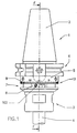
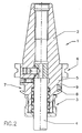
- a tool holder 1 can be seen in FIGS. 1 and 2 be, which consists of an upper cone part 2 and Insert the tool holder into the spindle of one Machine tool is used. Furthermore, one is known per se Device 3 for fastening the shaft 4 of a Tool shown.
- the body 5 of the tool holder 1 has a known one Device 6 for grasping the tool holder by means of a gripper.
- This circumferential groove 7 takes balancing weights 8 on.
- the circumferential groove 7 and the balance weights 8 are in the Connection described in more detail.
- two, three or four Balancing weights 8 arranged on the tool holder 1.
- the Balance weights 8 Before carrying out the balancing process, the Balance weights 8 with the same mutual distance in the groove 7 arranged.
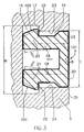
- FIG. 3 is the structural design of the circumferential groove 7 as well as the balance weights 8.
- the circumferential groove 7 forms a space 15, which is extends annularly around the tool holder 1.
- the annular space 15 is formed wider than that Inlet 16 (mouth) of the groove 7.
- the height H of the annular space 15 is therefore greater than the height I of the confluence 16.
- the annular space 15 connects with the opening 16 over a stop surface 17, which is an undercut forms.
- the circumferential groove 7 in the body 5 of the Tool holder a groove that is T-shaped.
- the balancing weight 8 has a U-shaped structure on average on.
- the arms 18, 19 of the U-shaped Balance weight 8 are elastically deformable.
- the outer surface of the arms 18 is advantageously and 19 at a distance from the surfaces 23, 34 of the confluence 16 provided.
- the thickenings 20, 21 are in the annular space 15 importable.
- the step-like surface 22 of the thickenings is with the an undercut forming surface 17 of the annular space 15 connectable.
- the thickenings 20, 21 taper outwards and form areas 100 which converge.
- the base 25 of the balance weight 8 is laterally on the Areas 23, 24.
- the balance weight 8 has a continuous Threaded hole 101 on.
- the threaded bore 101 is between the elastically deformable arms 18, 19 are arranged.
- a threaded pin 103 is in the threaded bore 101 screwed in to set the balance weight in the circumferential groove 7 is used.
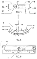
- FIGS 4, 5 and 6 can be a special embodiment the balance weight 8 are removed.
- the balancing weight 8 has the shape of a in this case Circular section.
- the elastic deformable arms 18, 19 are thickenings 20 on the outside, 21 provided.
- the surface 30 of the basic body 25 of the balancing weight 8 has a line scale 37, which is designed as a vernier is.
- the line scale 37 is advantageously one Line scale 10 assigned to the border 9 of the Circumferential groove 7 is provided.
- FIG. 6 can be a further embodiment of the Invention can be found.
- the circumferential groove 7 consists of an annular body 40, the removable with a cylindrical recess, the is incorporated into the body 5 of the tool holder 1, connected is.
- the ring-shaped body 40 has a continuous Threaded bore 41, which receives a threaded pin, the one in a threaded hole, the one in the cylindrical Recess of the body 5 of the tool holder 1 is provided is screwable.
- Balance weights 8 made of a suitable material and with certain length used.
- the outer surface 22 is in this position of the thickenings 20, 21 at the ready with one Undercut surface 17 of the ring-shaped Room 15.
- the balance weight 8 is only about Basic body 25 with the boundary surfaces 23, 24 of the Muzzle 16 in contact.
- the balance weight 8 is only a small one Resistance when moving inside the groove 7 opposite.
- the balancing weights 8 can therefore freely in the Circumferential groove are moved. This allows the location of the Center of gravity of the tool holder compared to its Axis of rotation can be changed.
- the threaded pin 103 is screwed in Spread apart the elastic arms 18, 19 after Outside.
Landscapes
- Engineering & Computer Science (AREA)
- General Engineering & Computer Science (AREA)
- Mechanical Engineering (AREA)
- Physics & Mathematics (AREA)
- Acoustics & Sound (AREA)
- Aviation & Aerospace Engineering (AREA)
- Testing Of Balance (AREA)
- Constituent Portions Of Griding Lathes, Driving, Sensing And Control (AREA)
- Jigs For Machine Tools (AREA)
Applications Claiming Priority (2)
| Application Number | Priority Date | Filing Date | Title |
|---|---|---|---|
| IT1998MI000941A IT1303052B1 (it) | 1998-04-30 | 1998-04-30 | Portautensile rotante con dispositivo di bilanciatura |
| ITMI980941 | 1998-04-30 |
Publications (3)
| Publication Number | Publication Date |
|---|---|
| EP0953404A2 true EP0953404A2 (fr) | 1999-11-03 |
| EP0953404A3 EP0953404A3 (fr) | 2001-12-12 |
| EP0953404B1 EP0953404B1 (fr) | 2003-10-29 |
Family
ID=11379933
Family Applications (1)
| Application Number | Title | Priority Date | Filing Date |
|---|---|---|---|
| EP99105519A Expired - Lifetime EP0953404B1 (fr) | 1998-04-30 | 1999-03-18 | Porte-outil rotatif avec dispositif d'équilibrage |
Country Status (5)
| Country | Link |
|---|---|
| US (1) | US6053678A (fr) |
| EP (1) | EP0953404B1 (fr) |
| AT (1) | ATE252963T1 (fr) |
| DE (1) | DE59907500D1 (fr) |
| IT (1) | IT1303052B1 (fr) |
Cited By (1)
| Publication number | Priority date | Publication date | Assignee | Title |
|---|---|---|---|---|
| DE10237041B4 (de) * | 2001-08-20 | 2017-09-14 | Rego-Fix Ag | Auswuchtsystem zum Unwuchtausgleich eines rotierenden Maschinenteils |
Families Citing this family (12)
| Publication number | Priority date | Publication date | Assignee | Title |
|---|---|---|---|---|
| US6530727B2 (en) * | 1998-04-13 | 2003-03-11 | Harmand Family Limited Partnership | Contour machining head |
| US6279420B1 (en) * | 1999-08-18 | 2001-08-28 | General Electric Co. | Balance weight for a rotary component in turbomachinery, methods of installation and installation tools |
| US6419427B1 (en) * | 1999-11-09 | 2002-07-16 | Paul S Galamba | Adjustable rotary tool providing a counter balanced system |
| JP2004066443A (ja) * | 2002-06-10 | 2004-03-04 | Nikken Kosakusho Works Ltd | 工具ホルダ |
| DE10250292A1 (de) | 2002-10-29 | 2004-05-13 | Carl Zeiss | Vorrichtung zum Massenausgleich einer rotierenden Spindel |
| US7305905B2 (en) * | 2004-01-09 | 2007-12-11 | The Bergquist Torrington Company | Rotatable member with an annular groove for dynamic balancing during rotation |
| EP1738865A1 (fr) * | 2005-06-29 | 2007-01-03 | August Rüggeberg GmbH & Co. KG | Porte-outil pour outils entraînés en rotation |
| US20100061818A1 (en) * | 2008-09-05 | 2010-03-11 | Parlec, Inc. | Diameter adjustment oriented balancing system |
| DE102013103168B3 (de) * | 2012-12-21 | 2014-04-17 | Franz Haimer Maschinenbau Kg | Werkzeughalter mit eingebauten Kavitäten |
| US9486862B1 (en) | 2014-07-25 | 2016-11-08 | Anthony P. LaMarca, Sr. | Fly cutter cutting tool |
| USD765747S1 (en) | 2015-05-16 | 2016-09-06 | Anthony P. LaMarca, Sr. | Fly cutter cutting tool |
| KR102633349B1 (ko) | 2018-03-02 | 2024-02-06 | 빅 다이쇼와 가부시키가이샤 | 회전 공구의 밸런스 및 오실레이션 조정 시스템, 밸런스 및 오실레이션 계측 장치, 밸런스 및 오실레이션 조정 방법, 및 공구 홀더 |
Family Cites Families (16)
| Publication number | Priority date | Publication date | Assignee | Title |
|---|---|---|---|---|
| JPS5852099B2 (ja) * | 1978-11-29 | 1983-11-19 | 株式会社日立製作所 | 回転体のバランスウエイト |
| CH663739A5 (de) * | 1984-03-21 | 1988-01-15 | Urma Werkzeug Maschf | Vorrichtung an einem durchmesserverstellbaren ausdrehwerkzeug mit schneidplattenhalter. |
| DE8708770U1 (de) * | 1987-06-24 | 1987-08-13 | PWZ Equipment Corp., Mauren | Werkzeugaufnahme |
| US4842485A (en) * | 1988-02-10 | 1989-06-27 | Westinghouse Electric Corp. | Balanced turbine rotor and method for making the same |
| US4865336A (en) * | 1988-06-03 | 1989-09-12 | Carboloy Inc. | Apparatus for securing a cutting tool in a tool holder and machine tools employing the same |
| US5074723A (en) * | 1989-04-13 | 1991-12-24 | Kennametal Inc. | Method and apparatus for balancing a rotary tool assembly |
| JP2512454Y2 (ja) * | 1989-12-18 | 1996-10-02 | 株式会社 大沢製作所 | 回転工具 |
| US5125777B1 (en) * | 1989-12-18 | 1998-02-03 | Eiichi Osawa | Rotary tool |
| FR2662103B1 (fr) * | 1990-05-15 | 1995-04-07 | Epb Emile Pfalzgraf Sa | Tete a aleser. |
| US5096345A (en) * | 1991-04-18 | 1992-03-17 | Hironobu Toyomoto | Balanceable holder for machine tools |
| SE9101692D0 (sv) * | 1991-06-04 | 1991-06-04 | Mircona Ab | Balansanordning vid skaerverktyg |
| JPH05177495A (ja) * | 1991-12-28 | 1993-07-20 | Daishowa Seiki Co Ltd | ツールホルダ |
| US5263995A (en) * | 1993-01-27 | 1993-11-23 | Kennametal Inc. | Apparatus and method for balancing a rotary tool assembly |
| CA2186723A1 (fr) * | 1994-03-29 | 1995-10-05 | Kennametal Hertel Ag Werkzeuge + Hartstoffe | Outil rotatif a bagues d'equilibrage |
| BR9401033A (pt) * | 1994-05-02 | 1994-11-01 | Romi Ind | Dispositivo compensador de massas, particularmente aplicável em cabeçote de broquear rotativo |
| ATE181007T1 (de) * | 1996-05-02 | 1999-06-15 | Kaiser Heinz Ag | Einschneidiger ausdrehkopf mit unwuchtausgleich |
-
1998
- 1998-04-30 IT IT1998MI000941A patent/IT1303052B1/it active IP Right Grant
-
1999
- 1999-03-10 US US09/266,143 patent/US6053678A/en not_active Expired - Fee Related
- 1999-03-18 DE DE59907500T patent/DE59907500D1/de not_active Expired - Fee Related
- 1999-03-18 AT AT99105519T patent/ATE252963T1/de not_active IP Right Cessation
- 1999-03-18 EP EP99105519A patent/EP0953404B1/fr not_active Expired - Lifetime
Cited By (1)
| Publication number | Priority date | Publication date | Assignee | Title |
|---|---|---|---|---|
| DE10237041B4 (de) * | 2001-08-20 | 2017-09-14 | Rego-Fix Ag | Auswuchtsystem zum Unwuchtausgleich eines rotierenden Maschinenteils |
Also Published As
| Publication number | Publication date |
|---|---|
| DE59907500D1 (de) | 2003-12-04 |
| IT1303052B1 (it) | 2000-10-23 |
| ATE252963T1 (de) | 2003-11-15 |
| EP0953404B1 (fr) | 2003-10-29 |
| EP0953404A3 (fr) | 2001-12-12 |
| US6053678A (en) | 2000-04-25 |
| ITMI980941A1 (it) | 1999-10-30 |
Similar Documents
| Publication | Publication Date | Title |
|---|---|---|
| EP0953404B1 (fr) | Porte-outil rotatif avec dispositif d'équilibrage | |
| DE69325723T2 (de) | Gerät und methode zum balancieren drehender werkzeuge | |
| CH663739A5 (de) | Vorrichtung an einem durchmesserverstellbaren ausdrehwerkzeug mit schneidplattenhalter. | |
| DE102006028729A1 (de) | Maschinenwerkzeug sowie Schneidring für ein Maschinenwerkzeug | |
| DE4038121C2 (fr) | ||
| DE3727487C2 (fr) | ||
| DE3322395C2 (fr) | ||
| DE10239422A1 (de) | Werkzeug zur spanenden Bearbeitung | |
| EP1201361B1 (fr) | Dispositif de support pour plusieurs mandrins | |
| EP0544658B1 (fr) | Outil de coupe servant a usiner les contours interieurs et exterieurs de pieces a usiner | |
| EP0913232A1 (fr) | Appareil pour l'usinage de pièces cylindriques | |
| EP1238730A1 (fr) | Mandrin de serrage | |
| CH627107A5 (en) | Fastening device with allocated, non-rotating tool or tool holder with cylindrical shank | |
| DE10237041A1 (de) | Auswuchtsystem zum Unwuchtausgleich eines rotierenden Maschinenteils | |
| DE2352013B2 (de) | Einrichtung zum glattwalzen einer gekruemmten rotationssymmetrischen aussenflaeche eines werkstuecks | |
| DE2121316A1 (de) | Stahlhalter für Bohrkopf | |
| DE10003291A1 (de) | Aufnahmefutter für optische Bauteile zum Feinschleifen und/oder Polieren | |
| DE8903660U1 (de) | Stützvorrichtung für Werkstücke | |
| DE20219338U1 (de) | Spanneinrichtung zur Befestigung eines Einzugsbolzens mit Nuten | |
| DE857903C (de) | Feinstbearbeitungswerkzeug fuer Gleitlagerbohrungen od. dgl. | |
| CH361216A (de) | Verfahren und Vorrichtung zum Nachbearbeiten von Werkstücken | |
| DE1095061B (de) | Schwingungsdaempfende Abstuetzung | |
| DE102023115420A1 (de) | Vorrichtung zur Aufnahme eines optischen Werkstücks für dessen Bearbeitung/Behandlung und Verfahren zum Aufnehmen eines optischen Werkstücks an einer solchen Vorrichtung | |
| CH616873A5 (fr) | ||
| DE2739740A1 (de) | Vorrichtung zum auswuchten von messersaetzen fuer einen kutter |
Legal Events
| Date | Code | Title | Description |
|---|---|---|---|
| PUAI | Public reference made under article 153(3) epc to a published international application that has entered the european phase |
Free format text: ORIGINAL CODE: 0009012 |
|
| AK | Designated contracting states |
Kind code of ref document: A2 Designated state(s): AT BE CH CY DE DK ES FI FR GB GR IE IT LI LU MC NL PT SE Kind code of ref document: A2 Designated state(s): AT BE CH DE DK ES FI FR GB IT LI NL PT SE |
|
| AX | Request for extension of the european patent |
Free format text: AL;LT;LV;MK;RO;SI |
|
| PUAL | Search report despatched |
Free format text: ORIGINAL CODE: 0009013 |
|
| AK | Designated contracting states |
Kind code of ref document: A3 Designated state(s): AT BE CH CY DE DK ES FI FR GB GR IE IT LI LU MC NL PT SE |
|
| AX | Request for extension of the european patent |
Free format text: AL;LT;LV;MK;RO;SI |
|
| RIC1 | Information provided on ipc code assigned before grant |
Free format text: 7B 23Q 11/00 A, 7F 16F 15/32 B, 7B 23B 31/117 B, 7B 23B 31/02 B, 7F 16F 15/34 B |
|
| AKX | Designation fees paid | ||
| REG | Reference to a national code |
Ref country code: DE Ref legal event code: 8566 |
|
| 17P | Request for examination filed |
Effective date: 20020321 |
|
| RBV | Designated contracting states (corrected) |
Designated state(s): AT BE CH DE DK ES FI FR GB IT LI NL PT SE |
|
| GRAH | Despatch of communication of intention to grant a patent |
Free format text: ORIGINAL CODE: EPIDOS IGRA |
|
| RIN1 | Information on inventor provided before grant (corrected) |
Inventor name: D'ANDREA ERMANNO |
|
| GRAS | Grant fee paid |
Free format text: ORIGINAL CODE: EPIDOSNIGR3 |
|
| GRAA | (expected) grant |
Free format text: ORIGINAL CODE: 0009210 |
|
| AK | Designated contracting states |
Kind code of ref document: B1 Designated state(s): AT BE CH DE DK ES FI FR GB IT LI NL PT SE |
|
| PG25 | Lapsed in a contracting state [announced via postgrant information from national office to epo] |
Ref country code: NL Free format text: LAPSE BECAUSE OF FAILURE TO SUBMIT A TRANSLATION OF THE DESCRIPTION OR TO PAY THE FEE WITHIN THE PRESCRIBED TIME-LIMIT Effective date: 20031029 Ref country code: IT Free format text: LAPSE BECAUSE OF FAILURE TO SUBMIT A TRANSLATION OF THE DESCRIPTION OR TO PAY THE FEE WITHIN THE PRESCRIBED TIME-LIMIT;WARNING: LAPSES OF ITALIAN PATENTS WITH EFFECTIVE DATE BEFORE 2007 MAY HAVE OCCURRED AT ANY TIME BEFORE 2007. THE CORRECT EFFECTIVE DATE MAY BE DIFFERENT FROM THE ONE RECORDED. Effective date: 20031029 Ref country code: GB Free format text: LAPSE BECAUSE OF FAILURE TO SUBMIT A TRANSLATION OF THE DESCRIPTION OR TO PAY THE FEE WITHIN THE PRESCRIBED TIME-LIMIT Effective date: 20031029 Ref country code: FI Free format text: LAPSE BECAUSE OF FAILURE TO SUBMIT A TRANSLATION OF THE DESCRIPTION OR TO PAY THE FEE WITHIN THE PRESCRIBED TIME-LIMIT Effective date: 20031029 |
|
| REG | Reference to a national code |
Ref country code: GB Ref legal event code: FG4D Free format text: NOT ENGLISH |
|
| REG | Reference to a national code |
Ref country code: CH Ref legal event code: EP |
|
| REG | Reference to a national code |
Ref country code: IE Ref legal event code: FG4D Free format text: GERMAN |
|
| REF | Corresponds to: |
Ref document number: 59907500 Country of ref document: DE Date of ref document: 20031204 Kind code of ref document: P |
|
| PG25 | Lapsed in a contracting state [announced via postgrant information from national office to epo] |
Ref country code: SE Free format text: LAPSE BECAUSE OF FAILURE TO SUBMIT A TRANSLATION OF THE DESCRIPTION OR TO PAY THE FEE WITHIN THE PRESCRIBED TIME-LIMIT Effective date: 20040129 Ref country code: DK Free format text: LAPSE BECAUSE OF FAILURE TO SUBMIT A TRANSLATION OF THE DESCRIPTION OR TO PAY THE FEE WITHIN THE PRESCRIBED TIME-LIMIT Effective date: 20040129 |
|
| PG25 | Lapsed in a contracting state [announced via postgrant information from national office to epo] |
Ref country code: ES Free format text: LAPSE BECAUSE OF FAILURE TO SUBMIT A TRANSLATION OF THE DESCRIPTION OR TO PAY THE FEE WITHIN THE PRESCRIBED TIME-LIMIT Effective date: 20040209 |
|
| PG25 | Lapsed in a contracting state [announced via postgrant information from national office to epo] |
Ref country code: AT Free format text: LAPSE BECAUSE OF NON-PAYMENT OF DUE FEES Effective date: 20040318 |
|
| PG25 | Lapsed in a contracting state [announced via postgrant information from national office to epo] |
Ref country code: LI Free format text: LAPSE BECAUSE OF NON-PAYMENT OF DUE FEES Effective date: 20040331 Ref country code: CH Free format text: LAPSE BECAUSE OF NON-PAYMENT OF DUE FEES Effective date: 20040331 Ref country code: BE Free format text: LAPSE BECAUSE OF NON-PAYMENT OF DUE FEES Effective date: 20040331 |
|
| NLV1 | Nl: lapsed or annulled due to failure to fulfill the requirements of art. 29p and 29m of the patents act | ||
| GBV | Gb: ep patent (uk) treated as always having been void in accordance with gb section 77(7)/1977 [no translation filed] |
Effective date: 20031029 |
|
| REG | Reference to a national code |
Ref country code: IE Ref legal event code: FD4D |
|
| ET | Fr: translation filed | ||
| PLBE | No opposition filed within time limit |
Free format text: ORIGINAL CODE: 0009261 |
|
| STAA | Information on the status of an ep patent application or granted ep patent |
Free format text: STATUS: NO OPPOSITION FILED WITHIN TIME LIMIT |
|
| BERE | Be: lapsed |
Owner name: D *ANDREA S.P.A. Effective date: 20040331 |
|
| 26N | No opposition filed |
Effective date: 20040730 |
|
| REG | Reference to a national code |
Ref country code: CH Ref legal event code: PL |
|
| PG25 | Lapsed in a contracting state [announced via postgrant information from national office to epo] |
Ref country code: PT Free format text: LAPSE BECAUSE OF NON-PAYMENT OF DUE FEES Effective date: 20040329 |
|
| PGFP | Annual fee paid to national office [announced via postgrant information from national office to epo] |
Ref country code: DE Payment date: 20090330 Year of fee payment: 11 |
|
| PGFP | Annual fee paid to national office [announced via postgrant information from national office to epo] |
Ref country code: FR Payment date: 20090325 Year of fee payment: 11 |
|
| REG | Reference to a national code |
Ref country code: FR Ref legal event code: ST Effective date: 20101130 |
|
| PG25 | Lapsed in a contracting state [announced via postgrant information from national office to epo] |
Ref country code: FR Free format text: LAPSE BECAUSE OF NON-PAYMENT OF DUE FEES Effective date: 20100331 |
|
| PG25 | Lapsed in a contracting state [announced via postgrant information from national office to epo] |
Ref country code: DE Free format text: LAPSE BECAUSE OF NON-PAYMENT OF DUE FEES Effective date: 20101001 |