EP0952702A2 - Rückwandverdrahtung mit zugeordneter Bandbreite für Datenvermittlung - Google Patents
Rückwandverdrahtung mit zugeordneter Bandbreite für Datenvermittlung Download PDFInfo
- Publication number
- EP0952702A2 EP0952702A2 EP99440076A EP99440076A EP0952702A2 EP 0952702 A2 EP0952702 A2 EP 0952702A2 EP 99440076 A EP99440076 A EP 99440076A EP 99440076 A EP99440076 A EP 99440076A EP 0952702 A2 EP0952702 A2 EP 0952702A2
- Authority
- EP
- European Patent Office
- Prior art keywords
- packet
- receive
- controller
- buses
- bus
- Prior art date
- Legal status (The legal status is an assumption and is not a legal conclusion. Google has not performed a legal analysis and makes no representation as to the accuracy of the status listed.)
- Granted
Links
Images

Classifications
-
- H—ELECTRICITY
- H04—ELECTRIC COMMUNICATION TECHNIQUE
- H04L—TRANSMISSION OF DIGITAL INFORMATION, e.g. TELEGRAPHIC COMMUNICATION
- H04L49/00—Packet switching elements
- H04L49/35—Switches specially adapted for specific applications
- H04L49/351—Switches specially adapted for specific applications for local area network [LAN], e.g. Ethernet switches
-
- H—ELECTRICITY
- H04—ELECTRIC COMMUNICATION TECHNIQUE
- H04L—TRANSMISSION OF DIGITAL INFORMATION, e.g. TELEGRAPHIC COMMUNICATION
- H04L12/00—Data switching networks
- H04L12/28—Data switching networks characterised by path configuration, e.g. LAN [Local Area Networks] or WAN [Wide Area Networks]
- H04L12/46—Interconnection of networks
- H04L12/4641—Virtual LANs, VLANs, e.g. virtual private networks [VPN]
-
- H—ELECTRICITY
- H04—ELECTRIC COMMUNICATION TECHNIQUE
- H04L—TRANSMISSION OF DIGITAL INFORMATION, e.g. TELEGRAPHIC COMMUNICATION
- H04L45/00—Routing or path finding of packets in data switching networks
- H04L45/74—Address processing for routing
- H04L45/745—Address table lookup; Address filtering
- H04L45/7453—Address table lookup; Address filtering using hashing
-
- H—ELECTRICITY
- H04—ELECTRIC COMMUNICATION TECHNIQUE
- H04L—TRANSMISSION OF DIGITAL INFORMATION, e.g. TELEGRAPHIC COMMUNICATION
- H04L49/00—Packet switching elements
- H04L49/35—Switches specially adapted for specific applications
- H04L49/354—Switches specially adapted for specific applications for supporting virtual local area networks [VLAN]
Definitions
- the present invention relates to data communication switching, and more particularly to local area network (LAN) switching.
- LAN local area network
- LAN switches interconnect network devices residing on different protocol domains.
- the switching functionality provided by LAN switches typically includes "local" switching between network devices on protocol domains interfacing with the same switching controller and "backplane" switching between network devices on protocol domains interfacing with different switching controllers.
- the backplanes used in LAN switch backplane switching have generally been configured as a packet bus shared by a plurality of controllers.
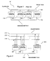
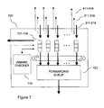
- a conventional LAN switch backplane is illustrated in Figure 1.
- LAN switch backplane 10 includes switching controllers 110, 120, 130 and a management controller 140 taking turns transmitting packets over packet bus 150 and asserting a shared claim line 160 to notify other controllers when they have captured a packet off bus 150.
- Management controller 140 is the "nerve center" of the backplane which assists switching controllers 110, 120, 130 in learning information for use in determining whether packets are to be captured or filtered and communicates such information to switching controllers 110, 120, 130 on management bus 170.
- orderly transmission over the packet bus is known to have been accomplished in several ways.
- One way is assigning the controllers different time slots in a repetitive timing cycle and granting control of the packet bus to the controllers round-robin in accordance with their assigned time slots.
- Another way involves conducting a priority-based arbitration among the controllers having packets for transmission and granting control of the bus to the controller which wins the arbitration.
- the present invention reduces transmit side congestion in a LAN switch backplane through the expedient of a backplane matrix in which each controller has a dedicated packet bus for propagating packet data.
- Each bus has a root interfacing with the transmitting (root) controller and a plurality of leaves interfacing with receiving (leaf) controllers.
- This configuration enables each controller to simultaneously transmit packet data on the root of a bus and receive packet data off a plurality of leaves of other buses without contention.
- An efficient filtering and stalling system employed at the receive side of the backplane prevents the highly parallel traffic from causing receive side congestion.
- each controller determines individually whether the destination address in a packet received on a packet bus corresponds to a forwarding address for the controller. If the destination address corresponds to a forwarding address for the controller, the controller captures the packet for forwarding and notifies other controllers of the capture on a claim line maintained between the controllers especially for the packet bus. Through the sharing of claim information on claim lines dedicated to particular packet buses, controllers which have not captured the packet are advised that the packet has a known destination addresses, such that the non-capturing controllers may filter the packet.
- leaf controllers notify the root controller if a forwarding queue for holding packets captured off a packet bus has insufficient room. To this end, a stall line is maintained between the leaf controllers and the root controller for each packet bus so it is known to which bus a stall signal relates.
- notified root controllers learn that they are transmitting packet data at an excessive rate and delay further transmission of packet data until notified that the congestion condition has abated.
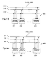
- Backplane 200 includes a matrix of packet buses 211-219 driven by controllers 201-209, respectively.
- Each bus has a root interfacing with the controller having the exclusive right to transmit packet data on the bus (i.e., the root controller) and leaves interfacing with the controllers receiving packet data off the bus (i.e., the leaf controllers).
- each controller is the root controller on one of buses 211-219 and is a leaf controller on all buses 211-219, including the bus for which it is the root controller.
- Packets are preferably transmitted on buses 211-219 in a series of constant-bit data bursts at a rate of one burst per clock cycle.
- Buses 211-219 are broadcast-oriented such that all data bursts propagated on a bus reach all controllers 201-209. Thus, on any particular clock cycle, all controllers 201-209 may transmit a single data burst and may receive a plurality of data bursts. It will be appreciated that by dedicating a packet bus to each one of controllers 201-209, there is no need to police transmission across backplane 200 under normal operating conditions. Of course, the number of root controller/packet bus pairs will vary depending on network requirements.
- management controller 209 serves as the "nerve center" of backplane 200 which assists switching controllers 201-208 in learning their respective forwarding addresses by transmitting such addresses on management bus 220.
- controllers 201-209 individually conduct filtering checks on each packet received off buses 211-219.
- filtering checks packet destination addresses are compared with the controller's forwarding addresses. Filtering checks result in each controller making a decision as to whether to capture for forwarding or filter each packet. The decision is generally made based on a determination of whether the packet contains a destination address recognized by the controller as a forwarding address.
- controllers 201-209 share the results of such determinations to avoid filtering packets whose destination address is not recognized by any controller as a forwarding address.
- Such "unknown destination" packets are captured by all controllers. More particularly, in an exemplary filtering check, a controller applies the following filtering rules:
- a stalling system is implemented to prevent receive side congestion during such high traffic periods.
- FIG 4 a preferred stall line architecture 400 implemented in conjunction with backplane 200 is shown.
- Architecture 400 has stall lines 411-419 for conveying stall signals.
- Each one of stall lines 411-419 relates congestion information for a different one of packet buses 201-209.
- Stall lines 411-419 are shared by leaf controllers for transmitting congestion information to the root controller for the packet bus.
- stall lines 411-419 relate to particular packet buses, the assertion of one of stall lines 411-419 will only suspend the flow of additional packet data from the root controller whose excessive rate transmission is causing the congestion condition. Transmission from other (unstalled) root controllers on their respective ones of packet buses 211-219 is advantageously allowed to continue.
- management controller 209 advises all controllers of virtual local area networks (VLANs) assigned to forwarding addresses active on any controller in backplane 200.
- VLAN lists advantageously allow controllers 201-209 to perform a VLAN check to determine if a captured packet's source and destination addresses are authorized to communicate, as indicated by their membership in a shared VLAN, before forwarding the packet on their associated protocol domains.
- controllers 201-209 perform VLAN checks using the VLAN membership for the source port, i.e., the port on which the packet arrived at the root controller, and the destination port, i.e., the port on which the packet would be allowed to leave leaf controller if the check were successful.
- port VLAN membership is defined such that source and destination ports are deemed members of all VLANs of which any network device known to reside on the protocol domain associated with the port is a member.
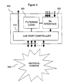
- Switching controller 201 operative on LAN switch backplane 200 is shown.
- Switching controller 201 is representative of switching controllers 201-208 and is also representative of the switching elements of management controller 209.
- management controller 209 has other elements for assisting source learning. Accordingly, management controller 209 may be regarded as an enhanced switching controller.
- Controller 201 includes LAN port controller 510 and receive interface 520 sharing filtering logic 530.
- LAN port controller 510 captures packets off protocol domains 540, formats them and propagates them on dedicated packet bus 211 as the root controller for that bus.
- receive interface 520 captures packets off packet buses 211-219 as one of the leaf controllers for that bus, formats them and forwards them to LAN port controller 510.
- LAN port controller 510 receives packets from receive interface 520, formats them and propagates them on protocol domains 540.
- controller 201 may be associated with one or more protocol domains, as network requirements demand. Transmit and receive processing are preferably performed on controller 201 using direct memory access (DMA) techniques implemented in integrated circuitry, although processor intervention is judiciously employed for configuration and relatively high-level tasks.
- Protocol domains 540 preferably each include one or more network devices operating in a particular communication protocol, such as Ethernet (operating at 10 Mbps, 10/100 Mbps, 100 Mbps or 1000 Mbps), Token Ring FDDI or ATM.
- controller 500 in addition to the functionality described herein, has segmentation and reassembly (SAR) logic to accomplish packet-to-cell and cell-to-packet conversions.
- SAR segmentation and reassembly
- controllers 201-209 sharing backplane 200 at the same time may support protocol domains operative in disparate communication protocols.
- one of controllers 201-209 may support Fast Ethernet protocol domains, while a second may support Token Ring protocol domains, and a third may support an ATM protocol domain.
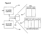
- Logic 530 is dual-ported for shared access by LAN port controller 510 and receive interface 520.
- Memory 630 may be accessed via transmit filter control 610 and receive filter control 620, associated with LAN port controller 510 and receive interfaces 520, respectively.
- Memory 630 includes a CAM 632 having entries holding, at different CAM indices, learned forwarding addresses of network devices residing on the controller's protocol domains. Forwarding addresses also may include configured flood addresses for forwarding broadcast packets.
- Memory 630 also includes CAM associated data 634 having entries linked to entries in CAM 632 or in the CAM on another one of controllers 202-209 by a common CAM index, CAM associated data entries include a flood field, a "last seen” field, a VLAN field and a port field.
- the flood field holds a flag indicating whether the entry is associated with a flood address.
- the "last seen” field holds a time stamp indicating the last time the entry was accessed.
- the VLAN field identifies the VLAN membership of the network device, if any, to which the entry relates.
- the VLAN field may include multi-bit numerical representations for each identified VLAN or may be in the form of a VLAN mask in which a VLAN is identified by the bit value retained at a position in the entry reserved for the VLAN.
- the port field identifies the number of the LAN port through which the network device to which the entry relates, if any, accesses controller 201.
- addresses submitted to CAM 632 return, in a single "look-up" operation, all indices at which a matching address resides. The returned indices may be advantageously used to consult the corresponding entry in CAM associated data 634 and retrieve information associated with the matching address.
- CAM 632 may be implemented in RAM.
- RAM random access memory
- Receive interface 520 operative on representative controller 201 is shown in greater detail.
- Receive interface 520 implements preferred filtering and stalling systems with the expedients of receive ports 701-709, receive filter control 620, watermark checker 710 and forwarding queue 720.
- Each receive port has a receive buffer fed with data bursts arriving off a different one of packet buses 211-219.
- each controller has a dedicated packet bus for transmitting data bursts to all controllers simultaneously.
- Receive ports 701-709 perform filtering checks and, where indicated, stalling checks on received packets and are assigned distinct "start release" clock cycles within a repetitive timing cycle such that, if both the filtering and stalling checks are passed, receive ports 701-709 may initiate the release of packets to forwarding queue 720 on their assigned "start release” clock cycles. Packets in forwarding queue 720 are eventually forwarded to LAN port controller 510 for a VLAN check and, where indicated, transmission on protocol domains 540. Receive ports 701-709, of course, have associated claim lines 311-319 and stall, lines 411-419 for employing, where indicated, in the preferred filtering and stalling systems.
- Packet 800 includes a base packet 810 and a packet bus header 820. Controllers 201-209 prepend packet bus headers to base packets before propagating them on buses 211-219 and strip packet bus headers off base packets before propagating them on protocol domains. Packet bus header 820 includes an offset, a CAM destination address field, a source port number field, a cyclic redundancy check field and a LAN protocol type field. Base packet 810 includes a Layer 2 destination address, a Layer 2 source address and a payload.
- the transmit processing flow begins when a packet propagated on a protocol domain arrives at the LAN port controller on one of controllers 201-209.
- the bit ordering of the packet's Layer 2 source and destination address is modified, if necessary, to comply with the bit ordering convention used in backplane 200 (910).
- different LAN protocols use different bit ordering conventions for Layer 2 addressing, e.g., most significant bit first (MSB) for Ethernet vs. least significant bit first (LSB) for Token Ring.
- the CAMs in all controllers sharing backplane 200 use a common bit ordering convention and Layer 2 addresses are modified, where necessary, to conform to the convention before CAM "look-ups" are performed on the addresses.
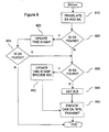
- the (convention-conforming) Layer 2 destination address is transferred to the controller's filtering logic for CAM "look-up" (920). If the destination address is found in the CAM, an index is returned, indicating that the destination address matches a forwarding address for the controller. In that event, the returned CAM index is used to access the corresponding entry in the controller's CAM associated data.
- the time stamp in the "last seen" field of the entry is updated to indicate that the entry has been accessed (922).
- addresses in CAM whose corresponding entries in CAM associated data have a "last seen” field whose time stamp has become sufficiently remote in time are deleted from the CAM.
- By updating the "last seen” field recently seen addresses are preserved while addresses not seen recently are allowed to be aged-out.
- the flood field in the accessed entry is reviewed to determine if the flood flag is set (924). In this regard, it bears noting that the controller's recognition of a packet's destination address as a forwarding address presents two possibilities: Either the packet's destination address is that assigned to a network device on one of the controller's associated protocol domains or is a flood address.
- the flood flag is not set, it is known that the packet's destination address is that of a network device on one of the controller's associated protocol domains. In that event, the packet will be switched locally, i.e. will not be transmitted on the packet bus, and no additional preparation of the packet for transmission on the packet bus is required. If, however, the flood flag is set, or if the destination addiess was not found in the CAM in the first place, transmission on the packet bus is indicated. In that event, the (convention-conforming) source address is transferred to the controller's filtering logic for a CAM "look-up" (930). If the source address is found in the CAM, an index is returned, indicating that the address matches a forwarding address for the controller.
- the returned CAM index is used to access the corresponding entry in the controller's CAM associated data and is encoded in the packet's source CAM index field and the time stamp in the accessed entry is updated (932). If, however, the source address is not found in the CAM, the address must be source-learned and bit reserved to indicate the need for source learning is set in the packet's source CAM index field (940). By setting the source learning bit, management controller 209 will know to capture the packet off the packet bus and subject the packet to the dynamic source learning process.
- the convention-conforming destination address is encoded in the packet's CAM destination address field, the number assigned to the port on which the packet arrived at the controller is encoded in the packet's source port number field and the packet is propagated on the controller's dedicated packet bus (950) to complete transmit processing.
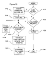
- the receive processing flow begins when a sufficient number of data bursts for a packet arrive off a packet bus in a receive port on a leaf controller's receive interface. Receive processing will be described for a representative leaf controller, but is performed simultaneously on all leaf controllers.
- the receive port sends to the controller's receive filter control a request for initiating a filtering check in the controller's CAM. If the receive filter control has only one request pending on a particular clock cycle, the request is automatically granted. If the receive filter control has multiple pending requests on a particular clock cycle, however, selection among the competing requests is resolved through arbitration.
- a claim signal is transmitted on the claim line associated with the receive port on which the packet is pending to indicate that the packet will be captured by the controller for forwarding, the returned CAM index is encoded in the packet's destination CAM index field (1012) and the packet is captured for forwarding (1022). If the destination address is not found in the CAM, however, the destination address is not recognized as a forwarding address for the controller. In that event, the controller listens on the claim line to whether another controller has claimed the packet (1020). If another controller has claimed the packet, the packet is known to be destined for a network device residing off another controller and the packet is dropped by the (non-claiming) controller (1030).
- a stall check is performed. (1025). For this purpose, receive ports are assigned distinct "start check" clock cycles within a repetitive timing cycle for initiating stall checks in watermark checker. Stall checks are conducted ensure that the hold queue has ample room to queue the captured packet. The outcome of stall check is based on consideration of the fullness of the forwarding queue, a maximum acceptable fullness level established for the forwarding queue (i.e., the watermark), and the size of the packet for queuing.
- stall check algorithm which may be advantageously implemented is described in Application Serial No.
- the receive port holding the captured packet continues to initiate stall checks on its assigned "start check” clock cycle until the stall check is passed, at which time the stall condition is lifted by deactivating the stall line.
- each receive port has a dedicated stall line and stall conditions are imposed on a "per port” basis to avoid unnecessary disruption of the flow of packets across backplane 200.
- the packet is released to the hold queue on the receive port's assigned “start release” clock cycle.
- the "start check" clock cycles assigned to a receive port for initiating stall checks may differ from its assigned “start release” clock cycle for commencing the release of a packet to the forwarding queue.
- Packets in the forwarding queue are eventually released to the controller's LAN port controller in a predetermined order.
- one or more VLAN checks are conducted to determine if the packet's source is authorized to communicate with the destination, as indicated by membership in a common VLAN (1045).
- the source CAM index and the destination CAM index from the packet are used to access the corresponding entries in leaf controller's CAM associated data and retrieve the VLAN membership for the comparison.
- the source CAM index will not be found if the packet's source address was not recognized in "look-up" conducted at the root controller.
- the destination CAM index will not be found if the packet's destination address was not recognized in the "look-up" conducted at the leaf controller. To the extent the source and destination CAM indices are not found, entries corresponding to the packet's source and destination ports are accessed to make the VLAN comparison.
- the destination port's VLAN membership is also used where the packet's destination address is a flood address. More particularly, VLAN checks are performed in the LAN port controller, and the packet is selectively forwarded on shared VLANs (1055), in accordance with the following VLAN rules:
Landscapes
- Engineering & Computer Science (AREA)
- Computer Networks & Wireless Communication (AREA)
- Signal Processing (AREA)
- Computer Security & Cryptography (AREA)
- Small-Scale Networks (AREA)
- Data Exchanges In Wide-Area Networks (AREA)
Applications Claiming Priority (4)
| Application Number | Priority Date | Filing Date | Title |
|---|---|---|---|
| US63493 | 1993-05-18 | ||
| US09/063,493 US6314106B1 (en) | 1998-04-20 | 1998-04-20 | Receive processing for dedicated bandwidth data communication switch backplane |
| US154966 | 1998-09-17 | ||
| US09/154,966 US7012896B1 (en) | 1998-04-20 | 1998-09-17 | Dedicated bandwidth data communication switch backplane |
Publications (3)
| Publication Number | Publication Date |
|---|---|
| EP0952702A2 true EP0952702A2 (de) | 1999-10-27 |
| EP0952702A3 EP0952702A3 (de) | 2002-10-30 |
| EP0952702B1 EP0952702B1 (de) | 2005-08-03 |
Family
ID=26743473
Family Applications (1)
| Application Number | Title | Priority Date | Filing Date |
|---|---|---|---|
| EP99440076A Expired - Lifetime EP0952702B1 (de) | 1998-04-20 | 1999-04-19 | Rückwandverdrahtung mit zugeordneter Bandbreite für Datenvermittlung |
Country Status (3)
| Country | Link |
|---|---|
| US (2) | US7012896B1 (de) |
| EP (1) | EP0952702B1 (de) |
| DE (1) | DE69926432T2 (de) |
Cited By (2)
| Publication number | Priority date | Publication date | Assignee | Title |
|---|---|---|---|---|
| WO2002010930A3 (en) * | 2000-07-28 | 2002-06-20 | Marconi Comm Inc | Protected ethernet backplane communication |
| US10735323B2 (en) * | 2016-01-26 | 2020-08-04 | Huawei Technologies Co., Ltd. | Service traffic allocation method and apparatus |
Families Citing this family (9)
| Publication number | Priority date | Publication date | Assignee | Title |
|---|---|---|---|---|
| US7012896B1 (en) * | 1998-04-20 | 2006-03-14 | Alcatel | Dedicated bandwidth data communication switch backplane |
| US20110214157A1 (en) * | 2000-09-25 | 2011-09-01 | Yevgeny Korsunsky | Securing a network with data flow processing |
| CA2366397A1 (en) * | 2001-12-31 | 2003-06-30 | Tropic Networks Inc. | An interface for data transfer between integrated circuits |
| TWI244868B (en) * | 2004-04-21 | 2005-12-01 | Wistron Corp | Resource sharing system for household electronic appliances |
| KR101084142B1 (ko) * | 2005-08-25 | 2011-11-17 | 엘지전자 주식회사 | 하향공유채널의 데이터 송수신 방법 |
| US7660318B2 (en) * | 2005-09-20 | 2010-02-09 | Cisco Technology, Inc. | Internetworking support between a LAN and a wireless mesh network |
| US20070110024A1 (en) * | 2005-11-14 | 2007-05-17 | Cisco Technology, Inc. | System and method for spanning tree cross routes |
| US8036115B2 (en) * | 2008-09-17 | 2011-10-11 | Intel Corporation | Synchronization of multiple incoming network communication streams |
| US11038995B2 (en) * | 2019-10-04 | 2021-06-15 | Nxp B.V. | Communications device and method of communications |
Family Cites Families (26)
| Publication number | Priority date | Publication date | Assignee | Title |
|---|---|---|---|---|
| CA1322390C (en) * | 1987-09-22 | 1993-09-21 | Nec Corporation | Star topology local area network |
| GB8802533D0 (en) * | 1988-02-04 | 1988-03-02 | Plessey Co Plc | Data packet switching |
| US5276818A (en) * | 1989-04-24 | 1994-01-04 | Hitachi, Ltd. | Bus system for information processing system and method of controlling the same |
| EP0438415B1 (de) | 1989-08-09 | 1995-01-18 | BELL TELEPHONE MANUFACTURING COMPANY Naamloze Vennootschap | Sequentielle rückordnung für einen vermittlungsknoten |
| GB9027663D0 (en) * | 1990-12-20 | 1991-02-13 | Sandoz Ltd | Light-stabilizing compositions |
| US5838894A (en) | 1992-12-17 | 1998-11-17 | Tandem Computers Incorporated | Logical, fail-functional, dual central processor units formed from three processor units |
| US5345447A (en) | 1993-02-05 | 1994-09-06 | Bytex Corporation | Switching hub which implements a virtual bus for interconnecting stations on a CSMA network |
| WO1994018766A1 (en) | 1993-02-09 | 1994-08-18 | Dsc Communications Corporation | High-speed packet bus |
| US5422880A (en) * | 1993-04-05 | 1995-06-06 | Stratacom, Inc. | Broadband switching fabric in a communication controller |
| DE4328862A1 (de) | 1993-08-27 | 1995-03-02 | Sel Alcatel Ag | Verfahren und Vorrichtung zum Zwischenspeichern von Datenpaketen sowie Vermittlungsstelle mit einer solchen Vorrichtung |
| IL110537A (en) * | 1994-08-01 | 1998-01-04 | 3Com Corp | Network switch |
| CA2157846A1 (en) * | 1994-09-09 | 1996-03-10 | Ashraf Mansur Dahod | Reconfigurable switch matrix for local area network |
| US5568476A (en) | 1994-10-26 | 1996-10-22 | 3Com Corporation | Method and apparatus for avoiding packet loss on a CSMA/CD-type local area network using receive-sense-based jam signal |
| US5499239A (en) * | 1995-04-14 | 1996-03-12 | Northern Telecom Limited | Large capacity modular ATM switch |
| US5729546A (en) * | 1995-06-21 | 1998-03-17 | Cisco Systems, Inc. | Expandable communication cell bus for multiplexing and concentrating communication cell traffic onto high speed lines |
| US5742602A (en) * | 1995-07-12 | 1998-04-21 | Compaq Computer Corporation | Adaptive repeater system |
| US6185222B1 (en) * | 1995-09-28 | 2001-02-06 | Cisco Technology, Inc. | Asymmetric switch architecture for use in a network switch node |
| US5815681A (en) | 1996-05-21 | 1998-09-29 | Elonex Plc Ltd. | Integrated network switching hub and bus structure |
| US6141323A (en) | 1996-06-03 | 2000-10-31 | Whittaker Corporation | Closed loop congestion control using a queue measurement system |
| US6097705A (en) * | 1997-01-06 | 2000-08-01 | Cabletron Systems, Inc. | Buffered repeater with independent ethernet collision domains |
| US6115387A (en) | 1997-02-14 | 2000-09-05 | Advanced Micro Devices, Inc. | Method and apparatus for controlling initiation of transmission of data as a function of received data |
| US6026075A (en) | 1997-02-25 | 2000-02-15 | International Business Machines Corporation | Flow control mechanism |
| US6023471A (en) * | 1997-10-07 | 2000-02-08 | Extreme Networks | Network interconnect device and protocol for communicating data among packet forwarding devices |
| US6084856A (en) | 1997-12-18 | 2000-07-04 | Advanced Micro Devices, Inc. | Method and apparatus for adjusting overflow buffers and flow control watermark levels |
| US6092108A (en) | 1998-03-19 | 2000-07-18 | Diplacido; Bruno | Dynamic threshold packet filtering of application processor frames |
| US7012896B1 (en) * | 1998-04-20 | 2006-03-14 | Alcatel | Dedicated bandwidth data communication switch backplane |
-
1998
- 1998-09-17 US US09/154,966 patent/US7012896B1/en not_active Expired - Fee Related
-
1999
- 1999-04-19 EP EP99440076A patent/EP0952702B1/de not_active Expired - Lifetime
- 1999-04-19 DE DE69926432T patent/DE69926432T2/de not_active Expired - Lifetime
-
2005
- 2005-09-21 US US11/231,920 patent/US7586849B2/en not_active Expired - Fee Related
Cited By (4)
| Publication number | Priority date | Publication date | Assignee | Title |
|---|---|---|---|---|
| WO2002010930A3 (en) * | 2000-07-28 | 2002-06-20 | Marconi Comm Inc | Protected ethernet backplane communication |
| US6804193B1 (en) | 2000-07-28 | 2004-10-12 | Marconi Intellectual Property (Ringfence) Inc. | Protected Ethernet backplane communication |
| US7240127B2 (en) | 2000-07-28 | 2007-07-03 | Telefonaktiebolaget Lm Ericsson (Publ) | Protected Ethernet backplane communication |
| US10735323B2 (en) * | 2016-01-26 | 2020-08-04 | Huawei Technologies Co., Ltd. | Service traffic allocation method and apparatus |
Also Published As
| Publication number | Publication date |
|---|---|
| DE69926432D1 (de) | 2005-09-08 |
| US20060013225A1 (en) | 2006-01-19 |
| US7012896B1 (en) | 2006-03-14 |
| US7586849B2 (en) | 2009-09-08 |
| EP0952702A3 (de) | 2002-10-30 |
| DE69926432T2 (de) | 2006-03-30 |
| EP0952702B1 (de) | 2005-08-03 |
Similar Documents
| Publication | Publication Date | Title |
|---|---|---|
| US6931019B2 (en) | Receive processing for dedicated bandwidth data communication switch backplane | |
| US7349416B2 (en) | Apparatus and method for distributing buffer status information in a switching fabric | |
| US6260073B1 (en) | Network switch including a switch manager for periodically polling the network ports to determine their status and controlling the flow of data between ports | |
| US8379524B1 (en) | Prioritization and preemption of data frames over a switching fabric | |
| EP1016246B1 (de) | Netzwerkvorrichtung und Verfahren zur Reduzierung der System-Latenz | |
| US6308218B1 (en) | Address look-up mechanism in a multi-port bridge for a local area network | |
| US6233246B1 (en) | Network switch with statistics read accesses | |
| EP1130855B1 (de) | Prioirtätsauswahlverfahren für ein Datenkommunikationsschalter | |
| US5898694A (en) | Method of round robin bus arbitration | |
| US6389480B1 (en) | Programmable arbitration system for determining priority of the ports of a network switch | |
| JP3806239B2 (ja) | 共用メモリ・システムを有するネットワーク・スイッチ | |
| US5796732A (en) | Architecture for an expandable transaction-based switching bus | |
| US6175571B1 (en) | Distributed memory switching hub | |
| US6154462A (en) | Circuits and methods for a ring network | |
| US6463032B1 (en) | Network switching system having overflow bypass in internal rules checker | |
| JP2001292155A (ja) | データ通信スイッチ用の優先順位リマッピング | |
| EP1356640B1 (de) | Modularer skalierbarer switch und verfahren zum verteilen schneller ethernet-datenrahmen | |
| KR20030085052A (ko) | 네트워크 장치에서의 선택적인 데이터 프레임 제거 | |
| EP0952702B1 (de) | Rückwandverdrahtung mit zugeordneter Bandbreite für Datenvermittlung | |
| US20030016625A1 (en) | Preclassifying traffic during periods of oversubscription | |
| US6084878A (en) | External rules checker interface | |
| US6301256B1 (en) | Selection technique for preventing a source port from becoming a destination port in a multi-port bridge for a local area network | |
| US6731601B1 (en) | Apparatus and method for resetting a retry counter in a network switch port in response to exerting backpressure | |
| US6181708B1 (en) | Lossless arbitration scheme and network architecture for collision based network protocols | |
| US6442168B1 (en) | High speed bus structure in a multi-port bridge for a local area network |
Legal Events
| Date | Code | Title | Description |
|---|---|---|---|
| PUAI | Public reference made under article 153(3) epc to a published international application that has entered the european phase |
Free format text: ORIGINAL CODE: 0009012 |
|
| AK | Designated contracting states |
Kind code of ref document: A2 Designated state(s): AT BE CH CY DE DK ES FI FR GB GR IE IT LI LU MC NL PT SE |
|
| AX | Request for extension of the european patent |
Free format text: AL;LT;LV;MK;RO;SI |
|
| RIC1 | Information provided on ipc code assigned before grant |
Free format text: 7H 04L 12/44 A, 7H 04L 12/28 B, 7H 04L 12/56 B, 7G 06F 13/40 B |
|
| PUAL | Search report despatched |
Free format text: ORIGINAL CODE: 0009013 |
|
| AK | Designated contracting states |
Kind code of ref document: A3 Designated state(s): AT BE CH CY DE DK ES FI FR GB GR IE IT LI LU MC NL PT SE |
|
| AX | Request for extension of the european patent |
Free format text: AL;LT;LV;MK;RO;SI |
|
| 17P | Request for examination filed |
Effective date: 20030123 |
|
| 17Q | First examination report despatched |
Effective date: 20030226 |
|
| AKX | Designation fees paid |
Designated state(s): DE ES FR GB IT |
|
| GRAP | Despatch of communication of intention to grant a patent |
Free format text: ORIGINAL CODE: EPIDOSNIGR1 |
|
| GRAS | Grant fee paid |
Free format text: ORIGINAL CODE: EPIDOSNIGR3 |
|
| GRAA | (expected) grant |
Free format text: ORIGINAL CODE: 0009210 |
|
| RAP1 | Party data changed (applicant data changed or rights of an application transferred) |
Owner name: ALCATEL |
|
| AK | Designated contracting states |
Kind code of ref document: B1 Designated state(s): DE ES FR GB IT |
|
| REG | Reference to a national code |
Ref country code: GB Ref legal event code: FG4D |
|
| REF | Corresponds to: |
Ref document number: 69926432 Country of ref document: DE Date of ref document: 20050908 Kind code of ref document: P |
|
| PG25 | Lapsed in a contracting state [announced via postgrant information from national office to epo] |
Ref country code: ES Free format text: LAPSE BECAUSE OF FAILURE TO SUBMIT A TRANSLATION OF THE DESCRIPTION OR TO PAY THE FEE WITHIN THE PRESCRIBED TIME-LIMIT Effective date: 20051114 |
|
| ET | Fr: translation filed | ||
| PLBE | No opposition filed within time limit |
Free format text: ORIGINAL CODE: 0009261 |
|
| STAA | Information on the status of an ep patent application or granted ep patent |
Free format text: STATUS: NO OPPOSITION FILED WITHIN TIME LIMIT |
|
| 26N | No opposition filed |
Effective date: 20060504 |
|
| REG | Reference to a national code |
Ref country code: GB Ref legal event code: 732E Free format text: REGISTERED BETWEEN 20131114 AND 20131120 |
|
| REG | Reference to a national code |
Ref country code: FR Ref legal event code: GC Effective date: 20140717 |
|
| REG | Reference to a national code |
Ref country code: FR Ref legal event code: RG Effective date: 20141016 |
|
| REG | Reference to a national code |
Ref country code: FR Ref legal event code: PLFP Year of fee payment: 17 |
|
| REG | Reference to a national code |
Ref country code: FR Ref legal event code: PLFP Year of fee payment: 18 |
|
| REG | Reference to a national code |
Ref country code: FR Ref legal event code: PLFP Year of fee payment: 19 |
|
| PGFP | Annual fee paid to national office [announced via postgrant information from national office to epo] |
Ref country code: DE Payment date: 20170419 Year of fee payment: 19 Ref country code: FR Payment date: 20170419 Year of fee payment: 19 Ref country code: GB Payment date: 20170419 Year of fee payment: 19 |
|
| PGFP | Annual fee paid to national office [announced via postgrant information from national office to epo] |
Ref country code: IT Payment date: 20170424 Year of fee payment: 19 |
|
| REG | Reference to a national code |
Ref country code: DE Ref legal event code: R119 Ref document number: 69926432 Country of ref document: DE |
|
| GBPC | Gb: european patent ceased through non-payment of renewal fee |
Effective date: 20180419 |
|
| PG25 | Lapsed in a contracting state [announced via postgrant information from national office to epo] |
Ref country code: DE Free format text: LAPSE BECAUSE OF NON-PAYMENT OF DUE FEES Effective date: 20181101 |
|
| PG25 | Lapsed in a contracting state [announced via postgrant information from national office to epo] |
Ref country code: GB Free format text: LAPSE BECAUSE OF NON-PAYMENT OF DUE FEES Effective date: 20180419 |
|
| PG25 | Lapsed in a contracting state [announced via postgrant information from national office to epo] |
Ref country code: IT Free format text: LAPSE BECAUSE OF NON-PAYMENT OF DUE FEES Effective date: 20180419 Ref country code: FR Free format text: LAPSE BECAUSE OF NON-PAYMENT OF DUE FEES Effective date: 20180430 |
|
| REG | Reference to a national code |
Ref country code: DE Ref legal event code: R082 Ref document number: 69926432 Country of ref document: DE Representative=s name: BARKHOFF REIMANN VOSSIUS, DE Ref country code: DE Ref legal event code: R081 Ref document number: 69926432 Country of ref document: DE Owner name: WSOU INVESTMENTS, LLC, LOS ANGELES, US Free format text: FORMER OWNER: ALCATEL LUCENT, PARIS, FR |
|
| REG | Reference to a national code |
Ref country code: GB Ref legal event code: 732E Free format text: REGISTERED BETWEEN 20200820 AND 20200826 |