EP0952446B1 - Monitoring - Google Patents
Monitoring Download PDFInfo
- Publication number
- EP0952446B1 EP0952446B1 EP99302311A EP99302311A EP0952446B1 EP 0952446 B1 EP0952446 B1 EP 0952446B1 EP 99302311 A EP99302311 A EP 99302311A EP 99302311 A EP99302311 A EP 99302311A EP 0952446 B1 EP0952446 B1 EP 0952446B1
- Authority
- EP
- European Patent Office
- Prior art keywords
- array
- component
- output
- flight
- monitoring system
- Prior art date
- Legal status (The legal status is an assumption and is not a legal conclusion. Google has not performed a legal analysis and makes no representation as to the accuracy of the status listed.)
- Expired - Lifetime
Links
Images
Classifications
-
- G—PHYSICS
- G01—MEASURING; TESTING
- G01N—INVESTIGATING OR ANALYSING MATERIALS BY DETERMINING THEIR CHEMICAL OR PHYSICAL PROPERTIES
- G01N29/00—Investigating or analysing materials by the use of ultrasonic, sonic or infrasonic waves; Visualisation of the interior of objects by transmitting ultrasonic or sonic waves through the object
- G01N29/22—Details, e.g. general constructional or apparatus details
- G01N29/28—Details, e.g. general constructional or apparatus details providing acoustic coupling, e.g. water
-
- G—PHYSICS
- G01—MEASURING; TESTING
- G01N—INVESTIGATING OR ANALYSING MATERIALS BY DETERMINING THEIR CHEMICAL OR PHYSICAL PROPERTIES
- G01N29/00—Investigating or analysing materials by the use of ultrasonic, sonic or infrasonic waves; Visualisation of the interior of objects by transmitting ultrasonic or sonic waves through the object
- G01N29/04—Analysing solids
- G01N29/07—Analysing solids by measuring propagation velocity or propagation time of acoustic waves
-
- G—PHYSICS
- G01—MEASURING; TESTING
- G01N—INVESTIGATING OR ANALYSING MATERIALS BY DETERMINING THEIR CHEMICAL OR PHYSICAL PROPERTIES
- G01N29/00—Investigating or analysing materials by the use of ultrasonic, sonic or infrasonic waves; Visualisation of the interior of objects by transmitting ultrasonic or sonic waves through the object
- G01N29/22—Details, e.g. general constructional or apparatus details
- G01N29/223—Supports, positioning or alignment in fixed situation
-
- G—PHYSICS
- G01—MEASURING; TESTING
- G01N—INVESTIGATING OR ANALYSING MATERIALS BY DETERMINING THEIR CHEMICAL OR PHYSICAL PROPERTIES
- G01N29/00—Investigating or analysing materials by the use of ultrasonic, sonic or infrasonic waves; Visualisation of the interior of objects by transmitting ultrasonic or sonic waves through the object
- G01N29/22—Details, e.g. general constructional or apparatus details
- G01N29/26—Arrangements for orientation or scanning by relative movement of the head and the sensor
- G01N29/262—Arrangements for orientation or scanning by relative movement of the head and the sensor by electronic orientation or focusing, e.g. with phased arrays
-
- G—PHYSICS
- G10—MUSICAL INSTRUMENTS; ACOUSTICS
- G10K—SOUND-PRODUCING DEVICES; METHODS OR DEVICES FOR PROTECTING AGAINST, OR FOR DAMPING, NOISE OR OTHER ACOUSTIC WAVES IN GENERAL; ACOUSTICS NOT OTHERWISE PROVIDED FOR
- G10K11/00—Methods or devices for transmitting, conducting or directing sound in general; Methods or devices for protecting against, or for damping, noise or other acoustic waves in general
- G10K11/18—Methods or devices for transmitting, conducting or directing sound
- G10K11/26—Sound-focusing or directing, e.g. scanning
- G10K11/34—Sound-focusing or directing, e.g. scanning using electrical steering of transducer arrays, e.g. beam steering
-
- G—PHYSICS
- G01—MEASURING; TESTING
- G01N—INVESTIGATING OR ANALYSING MATERIALS BY DETERMINING THEIR CHEMICAL OR PHYSICAL PROPERTIES
- G01N2291/00—Indexing codes associated with group G01N29/00
- G01N2291/02—Indexing codes associated with the analysed material
- G01N2291/023—Solids
- G01N2291/0231—Composite or layered materials
-
- G—PHYSICS
- G01—MEASURING; TESTING
- G01N—INVESTIGATING OR ANALYSING MATERIALS BY DETERMINING THEIR CHEMICAL OR PHYSICAL PROPERTIES
- G01N2291/00—Indexing codes associated with group G01N29/00
- G01N2291/04—Wave modes and trajectories
- G01N2291/044—Internal reflections (echoes), e.g. on walls or defects
-
- G—PHYSICS
- G01—MEASURING; TESTING
- G01N—INVESTIGATING OR ANALYSING MATERIALS BY DETERMINING THEIR CHEMICAL OR PHYSICAL PROPERTIES
- G01N2291/00—Indexing codes associated with group G01N29/00
- G01N2291/10—Number of transducers
- G01N2291/106—Number of transducers one or more transducer arrays
-
- G—PHYSICS
- G01—MEASURING; TESTING
- G01N—INVESTIGATING OR ANALYSING MATERIALS BY DETERMINING THEIR CHEMICAL OR PHYSICAL PROPERTIES
- G01N2291/00—Indexing codes associated with group G01N29/00
- G01N2291/26—Scanned objects
- G01N2291/269—Various geometry objects
- G01N2291/2694—Wings or other aircraft parts
Definitions
- This invention relates to monitoring systems of the kind including a component to be monitored, at least one phased acoustic array acoustically coupled with the component to receive acoustic energy from the component, and a monitor for monitoring the output of the array during use of the component.
- the invention is more particularly concerned with arrangements for monitoring defects caused during the life of a mechanical component, such as a component in an aircraft.
- Aircraft structural components and moving components can be subject to excessive stress, which can lead to damage in the components. It is known to attach stress monitors on such components. Although these can detect stress in the components they cannot detect defects arising from such stress. Defects within a component can be monitored by ground-based equipment during periodic inspection but this does not enable defects arising during use to be detected until the next inspection. In an aircraft, a defect caused during flight could lead to catastrophic failure unless action is taken to avoid this.
- DE 29 01 818 discloses a method for determining defects in materials by using ultrasound and a phased array.
- EP 0 518 508 which forms a starting point for claim 1 discusses a system for locating a fatigue point on a structure such as an aircraft employing a smart sensor patch having three triangularly adjacent acoustic sensors, said sensors providing an input to a central computer
- the monitor preferably provides the output in response to a change in output from the acoustic array.
- the array is preferably energized to generate acoustic energy propagated into the component and may be energized to scan a beam of acoustic energy in two planes.
- the array may be provided by a square of PZT material diced into an array of square elements and is preferably operative at ultrasonic frequencies.
- the system may include a plurality of arrays distributed over the component.
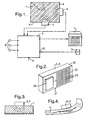
- the system comprises an aircraft component 1 (shown in section) such as a structural beam or the like and two sensors 2 and 3 bonded to adjacent faces 4 and 5 of the component inclined at right angles to one another.
- the sensors 2 and 3 are bonded to the component by a material, such as with an epoxy adhesive, which acoustically couples the sensor with the respective face of the component.
- the sensors and their wires may need to be protected from mechanical or chemical damage such as by means of a protective casing or by appropriate positioning.
- the sensors 2 and 3 are electrically connected with a monitor in the form of a processor unit 6, which provides outputs to a pilot's display 7 and to various flight control systems 8 within the aircraft.
- the processor unit 6 also has an output 9, to which ground test equipment can be connected, and has an input 10 connected to a pilot-operated control 11.
- the senor 2 which is identical with the other sensor 3, comprises a rectangular housing 20 with a flat front face 21 supporting a square matrix array 22 of deposited PZT material diced into an array of about ten by ten elements 23 extending in two orthogonal directions, each element being about 25 micron square. Different numbers and sizes of elements could be used.
- each element 23 When energized, each element 23 emits pulses at ultrasonic wavelengths.
- the array 22 is connected to a drive unit 24 within the housing 20, which also provides signal conditioning and buffer functions.
- the drive unit 24 drives the array 22 in a phased manner so that it produces a beam of ultrasonic energy that scans in two planes.
- the power output of the array 22 may be at low levels selected so that it is insufficient to cause fatigue or other damage to the structure being monitored.
- the array 22 receives signals reflected back from boundaries, interfaces, imperfections, defects or other discontinuities within the component 1.
- the drive unit 24 of each sensor 2 and 3 is connected to the processing unit 6, which monitors the outputs from the sensors to build up a three-dimensional representation of the component 1.
- the data may be monitored continuously or appropriately sampled or selected according to the processing capabilities.
- the processing unit 6 detects a change in the outputs of the sensors 2 and 3, it analyses the nature of this change using image processing technology to determine its effect.
- the change has a characteristic indicative of a weakening of the structure, such as a crack, or a potential future weakening, it provides an output to the pilot display 7 accordingly.
- the system can also respond to more gradual defects, such as caused by corrosion, as shown in Figure 3 , since the reflection from a corroded surface will generally be at a lower level or shifted in phase compared with reflections from an uncorroded surface. A gradual reduction or change in phase of a reflected signal can, therefore, be indicative of a build-up of corrosion.
- the system can also respond to defects on non-metallic structures, such as, for example, carbon fibre reinforced plastics or other composite materials, as shown in Figure 4 . Delamination within such materials will produce characteristic reflections within the thickness of the material.
- the display 7 preferably provides a display representation of the safe operational flight envelope for the aircraft given the nature of the detected defect.
- the pilot is then prompted to respond by operating the control 11, thereby signalling the processing unit 6 to provide output signals to the flight control systems 8.
- These output signals cause the systems 8 to limit the flight envelope of the aircraft such as to keep propagation of the defect to within acceptable limits relative to the estimated time to complete the flight.
- the limits on the flight envelope may be different according to the location of the detected defect.
- the system described enables a real-time monitoring of defects during flight of an aircraft so that any defects arising will be detected at an early stage and before they become catastrophic.
- the small size of the individual elements 23 of the array 22 enables the use of relatively short wavelength ultrasonic energy, giving them a relatively high resolution, which is more suitable for relatively thin and complex sections used in airframes. Because high quality metals are generally used in airframes, there is less scattering and attenuation compared with coarse grained and cast metals used in general engineering. The effect of signal attenuation and scattering will generally be greater in composite or laminated materials but aircraft structures tend to be relatively thin and de-lamination failures can be expected to produce a relatively large signal.
- the system can, therefore, respond to various defects such as caused by cracks, corrosion, voids and the separation of bonded or laminated structures. It can also respond to change in shape of the structure to which it is attached, such as defects caused by distortion, yielding and excessive motion. It can also detect defects caused by battle damage and may be able to detect embrittlement.
- a typical airframe might have many tens of sensors attached to structures known to be particularly subject to damage, or to structures that are particularly critical to safety. Alternatively, sensors could be distributed across the entire airframe or other system so that defects and stresses can be equalized. Sensors could be attached to moving structures, such as helicopter rotor blades, and signals supplied to and from the sensors either by slip rings or wireless telemetry. The overall data image produced by these sensors may be very complex but this need not be a problem since the system need only respond to changes in the data image, whether this be short-term or long-term.
- the system is non-destructive and does not cause any significant electromagnetic emission problems. As well as being used in-flight, it can also be used for pre-flight checks and maintenance.
- the sensors need not be permanently bonded to the structure being monitored, providing that there is a good acoustic coupling. This could be achieved by bolting the sensors in place and using an acoustic coupling substance to form an efficient interface between the sensor and the surface of the structure.
Landscapes
- Physics & Mathematics (AREA)
- Health & Medical Sciences (AREA)
- Life Sciences & Earth Sciences (AREA)
- Chemical & Material Sciences (AREA)
- Analytical Chemistry (AREA)
- Biochemistry (AREA)
- General Health & Medical Sciences (AREA)
- General Physics & Mathematics (AREA)
- Immunology (AREA)
- Pathology (AREA)
- Acoustics & Sound (AREA)
- Engineering & Computer Science (AREA)
- Multimedia (AREA)
- Investigating Or Analyzing Materials By The Use Of Ultrasonic Waves (AREA)
- Glass Compositions (AREA)
- Measurement Of Velocity Or Position Using Acoustic Or Ultrasonic Waves (AREA)
- Radar Systems Or Details Thereof (AREA)
Abstract
Description
- This invention relates to monitoring systems of the kind including a component to be monitored, at least one phased acoustic array acoustically coupled with the component to receive acoustic energy from the component, and a monitor for monitoring the output of the array during use of the component.
- The invention is more particularly concerned with arrangements for monitoring defects caused during the life of a mechanical component, such as a component in an aircraft.
- Aircraft structural components and moving components can be subject to excessive stress, which can lead to damage in the components. It is known to attach stress monitors on such components. Although these can detect stress in the components they cannot detect defects arising from such stress. Defects within a component can be monitored by ground-based equipment during periodic inspection but this does not enable defects arising during use to be detected until the next inspection. In an aircraft, a defect caused during flight could lead to catastrophic failure unless action is taken to avoid this.
-
DE 29 01 818 discloses a method for determining defects in materials by using ultrasound and a phased array. -
EP 0 518 508 which forms a starting point forclaim 1 discusses a system for locating a fatigue point on a structure such as an aircraft employing a smart sensor patch having three triangularly adjacent acoustic sensors, said sensors providing an input to a central computer - It is an object of the present invention to provide an improved monitoring system and method.
- According to the present invention there is provided a monitoring system of the above-specified kind, as defined in appended
claim 1. - The monitor preferably provides the output in response to a change in output from the acoustic array. The array is preferably energized to generate acoustic energy propagated into the component and may be energized to scan a beam of acoustic energy in two planes. The array may be provided by a square of PZT material diced into an array of square elements and is preferably operative at ultrasonic frequencies. The system may include a plurality of arrays distributed over the component.
- An aircraft monitoring system and its method of use, in accordance with the present invention, will now be described, by way of example, with reference to the accompanying drawings, in which:
- Figure 1
- is a schematic view of the system;
- Figure 2
- is a perspective view of a scanning sensor of the system;
- Figure 3
- shows use of the system to detect corrosion; and
- Figure 4
- shows use of the system to detect de-lamination.
- With reference first to
Figure 1 , the system comprises an aircraft component 1 (shown in section) such as a structural beam or the like and twosensors adjacent faces 4 and 5 of the component inclined at right angles to one another. Thesensors sensors processor unit 6, which provides outputs to a pilot's display 7 and to various flight control systems 8 within the aircraft. Theprocessor unit 6 also has anoutput 9, to which ground test equipment can be connected, and has aninput 10 connected to a pilot-operatedcontrol 11. - With reference now also to
Figure 2 , thesensor 2, which is identical with theother sensor 3, comprises arectangular housing 20 with aflat front face 21 supporting asquare matrix array 22 of deposited PZT material diced into an array of about ten by tenelements 23 extending in two orthogonal directions, each element being about 25 micron square. Different numbers and sizes of elements could be used. When energized, eachelement 23 emits pulses at ultrasonic wavelengths. Thearray 22 is connected to adrive unit 24 within thehousing 20, which also provides signal conditioning and buffer functions. Thedrive unit 24 drives thearray 22 in a phased manner so that it produces a beam of ultrasonic energy that scans in two planes. The power output of thearray 22 may be at low levels selected so that it is insufficient to cause fatigue or other damage to the structure being monitored. Thearray 22 receives signals reflected back from boundaries, interfaces, imperfections, defects or other discontinuities within thecomponent 1. Thedrive unit 24 of eachsensor processing unit 6, which monitors the outputs from the sensors to build up a three-dimensional representation of thecomponent 1. The data may be monitored continuously or appropriately sampled or selected according to the processing capabilities. When theprocessing unit 6 detects a change in the outputs of thesensors Figure 3 , since the reflection from a corroded surface will generally be at a lower level or shifted in phase compared with reflections from an uncorroded surface. A gradual reduction or change in phase of a reflected signal can, therefore, be indicative of a build-up of corrosion. The system can also respond to defects on non-metallic structures, such as, for example, carbon fibre reinforced plastics or other composite materials, as shown inFigure 4 . Delamination within such materials will produce characteristic reflections within the thickness of the material. - The display 7 preferably provides a display representation of the safe operational flight envelope for the aircraft given the nature of the detected defect. The pilot is then prompted to respond by operating the
control 11, thereby signalling theprocessing unit 6 to provide output signals to the flight control systems 8. These output signals cause the systems 8 to limit the flight envelope of the aircraft such as to keep propagation of the defect to within acceptable limits relative to the estimated time to complete the flight. The limits on the flight envelope may be different according to the location of the detected defect. The engine revs and the rates of manoeuvre, for example, could be limited. - The system described enables a real-time monitoring of defects during flight of an aircraft so that any defects arising will be detected at an early stage and before they become catastrophic.
- The small size of the
individual elements 23 of thearray 22 enables the use of relatively short wavelength ultrasonic energy, giving them a relatively high resolution, which is more suitable for relatively thin and complex sections used in airframes. Because high quality metals are generally used in airframes, there is less scattering and attenuation compared with coarse grained and cast metals used in general engineering. The effect of signal attenuation and scattering will generally be greater in composite or laminated materials but aircraft structures tend to be relatively thin and de-lamination failures can be expected to produce a relatively large signal. - The system can, therefore, respond to various defects such as caused by cracks, corrosion, voids and the separation of bonded or laminated structures. It can also respond to change in shape of the structure to which it is attached, such as defects caused by distortion, yielding and excessive motion. It can also detect defects caused by battle damage and may be able to detect embrittlement.
- A typical airframe might have many tens of sensors attached to structures known to be particularly subject to damage, or to structures that are particularly critical to safety. Alternatively, sensors could be distributed across the entire airframe or other system so that defects and stresses can be equalized. Sensors could be attached to moving structures, such as helicopter rotor blades, and signals supplied to and from the sensors either by slip rings or wireless telemetry. The overall data image produced by these sensors may be very complex but this need not be a problem since the system need only respond to changes in the data image, whether this be short-term or long-term.
- The system is non-destructive and does not cause any significant electromagnetic emission problems. As well as being used in-flight, it can also be used for pre-flight checks and maintenance.
- The sensors need not be permanently bonded to the structure being monitored, providing that there is a good acoustic coupling. This could be achieved by bolting the sensors in place and using an acoustic coupling substance to form an efficient interface between the sensor and the surface of the structure.
Claims (6)
- A monitoring system for monitoring defects in a component (1) of an aircraft in flight to be monitored, comprising:at least one phased acoustic array (22) acoustically coupled with the component (1) to receive acoustic energy from the component; anda monitor (6) in the formed of a processor unit (6) for monitoring the output of the array during use of the component; whereinthe at least one phased acoustic array (22) is fixed with the component in flight;the at least one phased acoustic array (22) is energized to generate acoustic energy propagated into the component (1)the at least one phased acoustic array (22) is responsive to defects arising during use of the component (1) and provides a first output in accordance therewith; andthe monitor (6) provides a second and third output in accordance with the first output of the at least one phased acoustic array; wherein:the second and third output are respectively further provided to a pilot's display (7) and to a output flight control system (8) in order to cause the flight control system (8) to limit the flight envelope of the aircraft such as to keep propagation of the defect to within acceptable limits relative to the estimated time to complete the flight.
- A monitoring system according to Claim 1, characterised in that the monitor (6) provides the second and third output in response to a change in the first output from the phased acoustic array (22).
- A monitoring system according to Claim 2, characterised in that the array (22) is energized to scan a beam of acoustic energy in two planes.
- A monitoring system according to any one of the preceding claims, characterised in that the array (22) is provided by a square of PZT material diced into an array of square elements (23).
- A monitoring system according to any one of the preceding claims, characterised in that the array (22) is operative at ultrasonic frequencies.
- A monitoring system according to any one of the preceding claims including a plurality of arrays (2, 3) distributed over the component (1).
Applications Claiming Priority (2)
| Application Number | Priority Date | Filing Date | Title |
|---|---|---|---|
| GBGB9808668.9A GB9808668D0 (en) | 1998-04-24 | 1998-04-24 | Monitoring |
| GB9808668 | 1998-04-24 |
Publications (3)
| Publication Number | Publication Date |
|---|---|
| EP0952446A2 EP0952446A2 (en) | 1999-10-27 |
| EP0952446A3 EP0952446A3 (en) | 2005-01-19 |
| EP0952446B1 true EP0952446B1 (en) | 2009-12-09 |
Family
ID=10830845
Family Applications (1)
| Application Number | Title | Priority Date | Filing Date |
|---|---|---|---|
| EP99302311A Expired - Lifetime EP0952446B1 (en) | 1998-04-24 | 1999-03-25 | Monitoring |
Country Status (6)
| Country | Link |
|---|---|
| US (1) | US6443012B2 (en) |
| EP (1) | EP0952446B1 (en) |
| JP (1) | JP4489866B2 (en) |
| AT (1) | ATE451609T1 (en) |
| DE (1) | DE69941754D1 (en) |
| GB (2) | GB9808668D0 (en) |
Families Citing this family (23)
| Publication number | Priority date | Publication date | Assignee | Title |
|---|---|---|---|---|
| JP2003185642A (en) * | 2001-12-14 | 2003-07-03 | Mitsubishi Heavy Ind Ltd | Separation inspection method and device for root of windmill blade of reinforced plastic |
| US7341758B2 (en) * | 2003-04-24 | 2008-03-11 | General Electric Company | Method for preparing and ultrasonically testing a thermal-spray coated article |
| DE10325406B4 (en) * | 2003-06-05 | 2005-04-28 | Eads Deutschland Gmbh | Damage determination on structures to be tested by means of ultrasound |
| IL160365A0 (en) * | 2004-02-12 | 2005-11-20 | Nexense Ltd | Method and apparatus for detecting panel conditions |
| US7817843B2 (en) | 2004-03-04 | 2010-10-19 | The Boeing Company | Manufacturing process or in service defects acoustic imaging using sensor array |
| US7080555B2 (en) * | 2004-06-04 | 2006-07-25 | Texas Research International, Inc. | Distributed mode system for real time acoustic emission monitoring |
| US6957582B1 (en) * | 2004-06-28 | 2005-10-25 | Simmonds Precision Products, Inc. | Ultrasonic system and method of gauging aircraft fuel and detecting battle damage |
| DE102005063073A1 (en) * | 2005-12-29 | 2007-07-12 | Airbus Deutschland Gmbh | Method of sizing and fabricating stiffened structural components, use of structural condition sensors and aircraft |
| FR2901610B1 (en) * | 2006-05-24 | 2009-01-16 | Airbus France Sas | DEVICE FOR NON-DESTRUCTIVE CONTROL OF STRUTURE BY VIBRATION ANALYSIS |
| US7636618B2 (en) | 2006-09-14 | 2009-12-22 | The Boeing Company | Responding to aircraft excursions from flight envelopes |
| US8594882B2 (en) * | 2008-01-16 | 2013-11-26 | The Boeing Company | Damage detection system |
| US7860664B2 (en) * | 2008-04-15 | 2010-12-28 | Spirit Aerosystems, Inc. | System and method for self-contained structural health monitoring for composite structures |
| US8365601B2 (en) * | 2011-01-04 | 2013-02-05 | Saudi Arabian Oil Company | High precision corrosion monitoring sensor assembly and system |
| KR101209787B1 (en) * | 2012-04-09 | 2012-12-11 | 삼성탈레스 주식회사 | Apparatus for disarming in combat unmanned aerial vehicles and method for operating the same |
| FR2992064B1 (en) * | 2012-06-19 | 2016-12-09 | Airbus Operations Sas | METHOD FOR NON-DESTRUCTIVE ULTRASONIC CONTROL OF LAMINATED COMPOSITE MATERIAL STRUCTURE |
| US20140020467A1 (en) * | 2012-07-17 | 2014-01-23 | Honeywell International Inc. | Non-destructive evaluation methods for machine-riveted bearings |
| JP6754584B2 (en) * | 2016-02-17 | 2020-09-16 | 帝人株式会社 | Monitoring device and monitoring method |
| US10444203B2 (en) * | 2016-09-15 | 2019-10-15 | Texas Instruments Incorporated | Ultrasonic vibration sensing |
| US11673352B2 (en) * | 2016-09-20 | 2023-06-13 | United States Of America As Represented By The Administrator Of Nasa | Automated wave guide system for in-process monitoring of carbon fiber reinforced polymer (CFRP) composite laminates with hanning window tone-bursts of center frequencies from 100-225 kHz and 100-350 kHz |
| CN106814141A (en) * | 2017-01-04 | 2017-06-09 | 天津大学 | A kind of phased array supersonic compression method based on orthogonal matching pursuit |
| US11119071B1 (en) | 2017-03-10 | 2021-09-14 | Oceangate, Inc. | Systems and methods for curing, testing, validating, rating, and monitoring the integrity of composite structures |
| WO2018217210A1 (en) * | 2017-05-26 | 2018-11-29 | Sikorsky Aircraft Corporation | Adaptive control of aircraft using structural health monitoring |
| US10641738B2 (en) | 2017-07-20 | 2020-05-05 | Airbus (S.A.S.) | Device and method for non-destructive ultrasound inspection of structures made of composite material |
Family Cites Families (34)
| Publication number | Priority date | Publication date | Assignee | Title |
|---|---|---|---|---|
| US4122725A (en) * | 1976-06-16 | 1978-10-31 | The United States Of America As Represented By The Administrator Of The National Aeronautics And Space Administration | Length mode piezoelectric ultrasonic transducer for inspection of solid objects |
| US4096755A (en) * | 1977-08-31 | 1978-06-27 | The Boeing Company | Ultrasonic inspection apparatus |
| US4212258A (en) * | 1978-05-12 | 1980-07-15 | International Submarine Services, S.A. | Underwater apparatus for acoustically inspecting a submerged object |
| DE2901818C2 (en) | 1979-01-18 | 1986-02-20 | Fraunhofer-Gesellschaft zur Förderung der angewandten Forschung e.V., 8000 München | Procedure for failure analysis in materials using ultrasound |
| US4271707A (en) * | 1979-11-16 | 1981-06-09 | Northrop Corporation | Received signal encoding and correlating system |
| US4497210A (en) | 1982-07-05 | 1985-02-05 | Tokyo Shibaura Denki Kabushiki Kaisha | Phased array ultrasonic testing apparatus and testing method therefor |
| DE3380939D1 (en) * | 1982-10-06 | 1990-01-11 | Welding Inst | ACOUSTIC DETECTING DEFECTS IN STRUCTURES. |
| US4537073A (en) * | 1982-12-24 | 1985-08-27 | Kabushiki Kaisha Kobe Seiko Sho | Inspection method of square billet using electronic scanning |
| JPS59116541A (en) * | 1982-12-24 | 1984-07-05 | Kobe Steel Ltd | Method for detecting flaw of square steel piece by using both electronic sector scanning and electronic linear scanning |
| US4524620A (en) * | 1983-02-07 | 1985-06-25 | Hughes Helicopters, Inc. | In-flight monitoring of composite structural components such as helicopter rotor blades |
| US4523468A (en) * | 1983-10-03 | 1985-06-18 | Trw Inc. | Phased array inspection of cylindrical objects |
| US4531411A (en) * | 1983-10-25 | 1985-07-30 | The United States Of America As Represented By The United States Department Of Energy | Acoustic emission linear pulse holography |
| JPS6115575A (en) * | 1984-06-28 | 1986-01-23 | Copal Denshi Kk | Rotating variation reducing method of motor |
| JPS61155755A (en) * | 1984-12-27 | 1986-07-15 | Toshiba Corp | Ultrasonic flaw detector |
| JPS6258103A (en) * | 1985-09-09 | 1987-03-13 | Nippon Kokan Kk <Nkk> | Method for ultrasonic flaw detection |
| JPS62156556A (en) * | 1985-12-27 | 1987-07-11 | Shunzo Morisane | Detecting method for defect of material of aircraft wing or the like |
| JPH063440B2 (en) * | 1986-10-06 | 1994-01-12 | 新日本製鐵株式会社 | Ultrasonic flaw detection method and device for welded steel pipe |
| JPH0827268B2 (en) * | 1986-12-12 | 1996-03-21 | 株式会社日立製作所 | Spatial scanning ultrasonic flaw detector |
| US4869071A (en) * | 1988-03-24 | 1989-09-26 | Sundstrand Corporation | Cooling system for an aircraft pod |
| US4910718A (en) * | 1988-10-05 | 1990-03-20 | Grumman Aerospace Corporation | Method and apparatus for acoustic emission monitoring |
| JPH02300657A (en) * | 1989-05-16 | 1990-12-12 | Mitsubishi Heavy Ind Ltd | Quality deciding method for adhesion part |
| JPH03122563A (en) * | 1989-10-05 | 1991-05-24 | Toshiba Corp | Ultrasonic flaw detection apparatus |
| US5293555A (en) | 1991-05-24 | 1994-03-08 | Hughes Aircraft Company | System and method for locating material fatigue using multiple sensors |
| US5184516A (en) * | 1991-07-31 | 1993-02-09 | Hughes Aircraft Company | Conformal circuit for structural health monitoring and assessment |
| JPH05188041A (en) * | 1992-01-14 | 1993-07-27 | Mitsubishi Heavy Ind Ltd | Method and device for inspecting water droplet in bonded honeycomb structure |
| US5337289A (en) * | 1993-07-16 | 1994-08-09 | The United States Of America As Represented By The Department Of Energy | Phased-array ultrasonic surface contour mapping system and method for solids hoppers and the like |
| DE69525629T2 (en) * | 1994-08-31 | 2002-08-29 | Honeywell, Inc. | SELF-SUPPLIED REMOTE STRUCTURE MONITORING |
| JPH08128996A (en) * | 1994-11-02 | 1996-05-21 | Toshiba Corp | Ultrasonic imaging device |
| US5823468A (en) * | 1995-10-24 | 1998-10-20 | Bothe; Hans-Jurgen | Hybrid aircraft |
| US5911158A (en) * | 1996-02-29 | 1999-06-08 | The United States Of America As Represented By The Secretary Of The Air Force | Piezoelectric strain sensor array |
| US5798458A (en) * | 1996-10-11 | 1998-08-25 | Raytheon Ti Systems, Inc. | Acoustic catastrophic event detection and data capture and retrieval system for aircraft |
| US5948984A (en) * | 1997-06-02 | 1999-09-07 | Hedberg; Carl Vance | Structural integrity recovery system |
| US6006163A (en) * | 1997-09-15 | 1999-12-21 | Mcdonnell Douglas Corporation | Active damage interrogation method for structural health monitoring |
| US6082198A (en) * | 1998-12-30 | 2000-07-04 | Electric Power Research Institute Inc. | Method of ultrasonically inspecting turbine blade attachments |
-
1998
- 1998-04-24 GB GBGB9808668.9A patent/GB9808668D0/en not_active Ceased
-
1999
- 1999-03-25 AT AT99302311T patent/ATE451609T1/en not_active IP Right Cessation
- 1999-03-25 DE DE69941754T patent/DE69941754D1/en not_active Expired - Lifetime
- 1999-03-25 EP EP99302311A patent/EP0952446B1/en not_active Expired - Lifetime
- 1999-04-01 US US09/283,279 patent/US6443012B2/en not_active Expired - Lifetime
- 1999-04-01 GB GB9907532A patent/GB2336676B/en not_active Expired - Lifetime
- 1999-04-06 JP JP09893999A patent/JP4489866B2/en not_active Expired - Lifetime
Also Published As
| Publication number | Publication date |
|---|---|
| GB9808668D0 (en) | 1998-06-24 |
| GB9907532D0 (en) | 1999-05-26 |
| DE69941754D1 (en) | 2010-01-21 |
| US20020000125A1 (en) | 2002-01-03 |
| EP0952446A3 (en) | 2005-01-19 |
| GB2336676A (en) | 1999-10-27 |
| JP4489866B2 (en) | 2010-06-23 |
| GB2336676B (en) | 2002-05-01 |
| ATE451609T1 (en) | 2009-12-15 |
| EP0952446A2 (en) | 1999-10-27 |
| US6443012B2 (en) | 2002-09-03 |
| JPH11326293A (en) | 1999-11-26 |
Similar Documents
| Publication | Publication Date | Title |
|---|---|---|
| EP0952446B1 (en) | Monitoring | |
| Hofer | Fibre optic damage detection in composite structures | |
| EP0066923A2 (en) | Aircraft structural integrity assessment system | |
| Salamone et al. | High-velocity impact location on aircraft panels using macro-fiber composite piezoelectric rosettes | |
| US4524620A (en) | In-flight monitoring of composite structural components such as helicopter rotor blades | |
| EP2511701B1 (en) | Transducer based structural health monitoring system | |
| US20090189020A1 (en) | Aerodynamic Profile for Aircraft and Wind Power Stations and Method of Measuring the Thickness of Ice on an Aerodynamic Profile | |
| Güemes | SHM technologies and applications in aircraft structures | |
| EP2594912A1 (en) | Detection system for detection of damages on rotating components of aircraft and method of operating such a detection system | |
| JP2003515730A (en) | Diagnostic layers and methods for detecting structural integrity of composite and metallic materials | |
| EP2462433B1 (en) | System and method for detecting an anomaly in a hidden portion of a multi-layer structure | |
| Boller et al. | Aircraft structural health and usage monitoring | |
| WO2005036162A1 (en) | System for multiplexing acoustic emission (ae) instrumentation | |
| US5338928A (en) | System and method for controlling deformation of a structure having a phase shift detector | |
| JPS5830899A (en) | Valueing system for safety of aircraft structure | |
| US4297885A (en) | Acoustic emission for detection and monitoring of crack initiation and propagation in materials | |
| Hsu | Nondestructive evaluation of sandwich structures: a review of some inspection techniques | |
| CN113484418A (en) | Damage cooperative diagnosis technology based on multi-frequency domain response signals | |
| Varadan et al. | Wireless remotely readable and programmable microsensors and MEMS for health monitoring of aircraft structures | |
| JP2003166875A (en) | Abnormality inspection device and abnormality inspection method of rotor | |
| EP1659400A1 (en) | Piezotransducer arrays for structural health monitoring | |
| CA1179529A (en) | Aircraft structural integrity system | |
| Sendeckyj et al. | Some smart structures concepts | |
| Varadan et al. | Microsensors and MEMS for health monitoring of composite and aircraft structures in flight | |
| Kuznetsov et al. | Lamb Wave Interaction with a Fatigue Crack in a Thin Sheet of Al2024-T3 |
Legal Events
| Date | Code | Title | Description |
|---|---|---|---|
| PUAI | Public reference made under article 153(3) epc to a published international application that has entered the european phase |
Free format text: ORIGINAL CODE: 0009012 |
|
| AK | Designated contracting states |
Kind code of ref document: A2 Designated state(s): AT BE CH CY DE DK ES FI FR GB GR IE IT LI LU MC NL PT SE |
|
| AX | Request for extension of the european patent |
Free format text: AL;LT;LV;MK;RO;SI |
|
| PUAL | Search report despatched |
Free format text: ORIGINAL CODE: 0009013 |
|
| AK | Designated contracting states |
Kind code of ref document: A3 Designated state(s): AT BE CH CY DE DK ES FI FR GB GR IE IT LI LU MC NL PT SE |
|
| AX | Request for extension of the european patent |
Extension state: AL LT LV MK RO SI |
|
| RIC1 | Information provided on ipc code assigned before grant |
Ipc: 7G 01N 29/26 B Ipc: 7G 01N 27/10 A |
|
| 17P | Request for examination filed |
Effective date: 20050519 |
|
| AKX | Designation fees paid |
Designated state(s): AT BE CH CY DE DK ES FI FR GB GR IE IT LI LU MC NL PT SE |
|
| RAP1 | Party data changed (applicant data changed or rights of an application transferred) |
Owner name: GE AVIATION UK |
|
| GRAP | Despatch of communication of intention to grant a patent |
Free format text: ORIGINAL CODE: EPIDOSNIGR1 |
|
| GRAS | Grant fee paid |
Free format text: ORIGINAL CODE: EPIDOSNIGR3 |
|
| GRAA | (expected) grant |
Free format text: ORIGINAL CODE: 0009210 |
|
| AK | Designated contracting states |
Kind code of ref document: B1 Designated state(s): AT BE CH CY DE DK ES FI FR GB GR IE IT LI LU MC NL PT SE |
|
| REG | Reference to a national code |
Ref country code: GB Ref legal event code: FG4D |
|
| REG | Reference to a national code |
Ref country code: CH Ref legal event code: EP |
|
| REG | Reference to a national code |
Ref country code: IE Ref legal event code: FG4D |
|
| REF | Corresponds to: |
Ref document number: 69941754 Country of ref document: DE Date of ref document: 20100121 Kind code of ref document: P |
|
| REG | Reference to a national code |
Ref country code: NL Ref legal event code: VDEP Effective date: 20091209 |
|
| PG25 | Lapsed in a contracting state [announced via postgrant information from national office to epo] |
Ref country code: SE Free format text: LAPSE BECAUSE OF FAILURE TO SUBMIT A TRANSLATION OF THE DESCRIPTION OR TO PAY THE FEE WITHIN THE PRESCRIBED TIME-LIMIT Effective date: 20091209 Ref country code: FI Free format text: LAPSE BECAUSE OF FAILURE TO SUBMIT A TRANSLATION OF THE DESCRIPTION OR TO PAY THE FEE WITHIN THE PRESCRIBED TIME-LIMIT Effective date: 20091209 |
|
| PG25 | Lapsed in a contracting state [announced via postgrant information from national office to epo] |
Ref country code: AT Free format text: LAPSE BECAUSE OF FAILURE TO SUBMIT A TRANSLATION OF THE DESCRIPTION OR TO PAY THE FEE WITHIN THE PRESCRIBED TIME-LIMIT Effective date: 20091209 |
|
| PG25 | Lapsed in a contracting state [announced via postgrant information from national office to epo] |
Ref country code: PT Free format text: LAPSE BECAUSE OF FAILURE TO SUBMIT A TRANSLATION OF THE DESCRIPTION OR TO PAY THE FEE WITHIN THE PRESCRIBED TIME-LIMIT Effective date: 20100409 Ref country code: NL Free format text: LAPSE BECAUSE OF FAILURE TO SUBMIT A TRANSLATION OF THE DESCRIPTION OR TO PAY THE FEE WITHIN THE PRESCRIBED TIME-LIMIT Effective date: 20091209 Ref country code: ES Free format text: LAPSE BECAUSE OF FAILURE TO SUBMIT A TRANSLATION OF THE DESCRIPTION OR TO PAY THE FEE WITHIN THE PRESCRIBED TIME-LIMIT Effective date: 20100320 |
|
| PG25 | Lapsed in a contracting state [announced via postgrant information from national office to epo] |
Ref country code: BE Free format text: LAPSE BECAUSE OF FAILURE TO SUBMIT A TRANSLATION OF THE DESCRIPTION OR TO PAY THE FEE WITHIN THE PRESCRIBED TIME-LIMIT Effective date: 20091209 |
|
| PLBE | No opposition filed within time limit |
Free format text: ORIGINAL CODE: 0009261 |
|
| STAA | Information on the status of an ep patent application or granted ep patent |
Free format text: STATUS: NO OPPOSITION FILED WITHIN TIME LIMIT |
|
| PG25 | Lapsed in a contracting state [announced via postgrant information from national office to epo] |
Ref country code: MC Free format text: LAPSE BECAUSE OF NON-PAYMENT OF DUE FEES Effective date: 20100331 Ref country code: GR Free format text: LAPSE BECAUSE OF FAILURE TO SUBMIT A TRANSLATION OF THE DESCRIPTION OR TO PAY THE FEE WITHIN THE PRESCRIBED TIME-LIMIT Effective date: 20100310 Ref country code: CY Free format text: LAPSE BECAUSE OF FAILURE TO SUBMIT A TRANSLATION OF THE DESCRIPTION OR TO PAY THE FEE WITHIN THE PRESCRIBED TIME-LIMIT Effective date: 20091209 |
|
| REG | Reference to a national code |
Ref country code: CH Ref legal event code: PL |
|
| 26N | No opposition filed |
Effective date: 20100910 |
|
| PG25 | Lapsed in a contracting state [announced via postgrant information from national office to epo] |
Ref country code: IE Free format text: LAPSE BECAUSE OF NON-PAYMENT OF DUE FEES Effective date: 20100325 Ref country code: DK Free format text: LAPSE BECAUSE OF FAILURE TO SUBMIT A TRANSLATION OF THE DESCRIPTION OR TO PAY THE FEE WITHIN THE PRESCRIBED TIME-LIMIT Effective date: 20091209 |
|
| PG25 | Lapsed in a contracting state [announced via postgrant information from national office to epo] |
Ref country code: LI Free format text: LAPSE BECAUSE OF NON-PAYMENT OF DUE FEES Effective date: 20100331 Ref country code: CH Free format text: LAPSE BECAUSE OF NON-PAYMENT OF DUE FEES Effective date: 20100331 |
|
| PG25 | Lapsed in a contracting state [announced via postgrant information from national office to epo] |
Ref country code: IT Free format text: LAPSE BECAUSE OF FAILURE TO SUBMIT A TRANSLATION OF THE DESCRIPTION OR TO PAY THE FEE WITHIN THE PRESCRIBED TIME-LIMIT Effective date: 20091209 |
|
| PG25 | Lapsed in a contracting state [announced via postgrant information from national office to epo] |
Ref country code: LU Free format text: LAPSE BECAUSE OF NON-PAYMENT OF DUE FEES Effective date: 20100325 |
|
| REG | Reference to a national code |
Ref country code: FR Ref legal event code: PLFP Year of fee payment: 18 |
|
| REG | Reference to a national code |
Ref country code: FR Ref legal event code: PLFP Year of fee payment: 19 |
|
| REG | Reference to a national code |
Ref country code: FR Ref legal event code: PLFP Year of fee payment: 20 |
|
| PGFP | Annual fee paid to national office [announced via postgrant information from national office to epo] |
Ref country code: GB Payment date: 20180327 Year of fee payment: 20 |
|
| PGFP | Annual fee paid to national office [announced via postgrant information from national office to epo] |
Ref country code: FR Payment date: 20180326 Year of fee payment: 20 |
|
| PGFP | Annual fee paid to national office [announced via postgrant information from national office to epo] |
Ref country code: DE Payment date: 20180328 Year of fee payment: 20 |
|
| REG | Reference to a national code |
Ref country code: DE Ref legal event code: R071 Ref document number: 69941754 Country of ref document: DE |
|
| REG | Reference to a national code |
Ref country code: GB Ref legal event code: PE20 Expiry date: 20190324 |
|
| PG25 | Lapsed in a contracting state [announced via postgrant information from national office to epo] |
Ref country code: GB Free format text: LAPSE BECAUSE OF EXPIRATION OF PROTECTION Effective date: 20190324 |