EP0952293B1 - Porte basculante motorisee a ressorts lateraux ou pistons a gaz du type a deplacement circulaire - Google Patents
Porte basculante motorisee a ressorts lateraux ou pistons a gaz du type a deplacement circulaire Download PDFInfo
- Publication number
- EP0952293B1 EP0952293B1 EP19990440089 EP99440089A EP0952293B1 EP 0952293 B1 EP0952293 B1 EP 0952293B1 EP 19990440089 EP19990440089 EP 19990440089 EP 99440089 A EP99440089 A EP 99440089A EP 0952293 B1 EP0952293 B1 EP 0952293B1
- Authority
- EP
- European Patent Office
- Prior art keywords
- lever
- rotation
- coupled
- movement
- transmission lever
- Prior art date
- Legal status (The legal status is an assumption and is not a legal conclusion. Google has not performed a legal analysis and makes no representation as to the accuracy of the status listed.)
- Expired - Lifetime
Links
- 230000033001 locomotion Effects 0.000 title claims description 40
- 230000005540 biological transmission Effects 0.000 claims description 35
- 230000007246 mechanism Effects 0.000 claims description 10
- 230000008878 coupling Effects 0.000 claims description 5
- 238000010168 coupling process Methods 0.000 claims description 5
- 238000005859 coupling reaction Methods 0.000 claims description 5
- 230000000295 complement effect Effects 0.000 claims description 3
- 238000006073 displacement reaction Methods 0.000 description 7
- 238000009434 installation Methods 0.000 description 3
- 230000009471 action Effects 0.000 description 2
- 230000000694 effects Effects 0.000 description 2
- 235000021183 entrée Nutrition 0.000 description 2
- 238000000034 method Methods 0.000 description 2
- 210000000481 breast Anatomy 0.000 description 1
- 230000015556 catabolic process Effects 0.000 description 1
- 238000010276 construction Methods 0.000 description 1
- 230000036461 convulsion Effects 0.000 description 1
- 238000009429 electrical wiring Methods 0.000 description 1
- 235000013305 food Nutrition 0.000 description 1
- 238000004519 manufacturing process Methods 0.000 description 1
- 230000004048 modification Effects 0.000 description 1
- 238000012986 modification Methods 0.000 description 1
- 210000000056 organ Anatomy 0.000 description 1
- 230000003071 parasitic effect Effects 0.000 description 1
- 238000003825 pressing Methods 0.000 description 1
- 230000001360 synchronised effect Effects 0.000 description 1
- 238000013024 troubleshooting Methods 0.000 description 1
Images


Classifications
-
- E—FIXED CONSTRUCTIONS
- E05—LOCKS; KEYS; WINDOW OR DOOR FITTINGS; SAFES
- E05F—DEVICES FOR MOVING WINGS INTO OPEN OR CLOSED POSITION; CHECKS FOR WINGS; WING FITTINGS NOT OTHERWISE PROVIDED FOR, CONCERNED WITH THE FUNCTIONING OF THE WING
- E05F15/00—Power-operated mechanisms for wings
- E05F15/60—Power-operated mechanisms for wings using electrical actuators
- E05F15/603—Power-operated mechanisms for wings using electrical actuators using rotary electromotors
- E05F15/665—Power-operated mechanisms for wings using electrical actuators using rotary electromotors for vertically-sliding wings
- E05F15/668—Power-operated mechanisms for wings using electrical actuators using rotary electromotors for vertically-sliding wings for overhead wings
- E05F15/678—Power-operated mechanisms for wings using electrical actuators using rotary electromotors for vertically-sliding wings for overhead wings operated by swinging lever arms
-
- E—FIXED CONSTRUCTIONS
- E05—LOCKS; KEYS; WINDOW OR DOOR FITTINGS; SAFES
- E05D—HINGES OR SUSPENSION DEVICES FOR DOORS, WINDOWS OR WINGS
- E05D13/00—Accessories for sliding or lifting wings, e.g. pulleys, safety catches
- E05D13/10—Counterbalance devices
- E05D13/12—Counterbalance devices with springs
- E05D13/1207—Counterbalance devices with springs with tension springs
- E05D13/1215—Counterbalance devices with springs with tension springs specially adapted for overhead wings
-
- E—FIXED CONSTRUCTIONS
- E05—LOCKS; KEYS; WINDOW OR DOOR FITTINGS; SAFES
- E05D—HINGES OR SUSPENSION DEVICES FOR DOORS, WINDOWS OR WINGS
- E05D15/00—Suspension arrangements for wings
- E05D15/40—Suspension arrangements for wings supported on arms movable in vertical planes
- E05D15/406—Suspension arrangements for wings supported on arms movable in vertical planes with pivoted arms and sliding guides
- E05D15/408—Suspension arrangements for wings supported on arms movable in vertical planes with pivoted arms and sliding guides with sliding guides fixed to the wing
-
- E—FIXED CONSTRUCTIONS
- E05—LOCKS; KEYS; WINDOW OR DOOR FITTINGS; SAFES
- E05Y—INDEXING SCHEME ASSOCIATED WITH SUBCLASSES E05D AND E05F, RELATING TO CONSTRUCTION ELEMENTS, ELECTRIC CONTROL, POWER SUPPLY, POWER SIGNAL OR TRANSMISSION, USER INTERFACES, MOUNTING OR COUPLING, DETAILS, ACCESSORIES, AUXILIARY OPERATIONS NOT OTHERWISE PROVIDED FOR, APPLICATION THEREOF
- E05Y2900/00—Application of doors, windows, wings or fittings thereof
- E05Y2900/10—Application of doors, windows, wings or fittings thereof for buildings or parts thereof
- E05Y2900/106—Application of doors, windows, wings or fittings thereof for buildings or parts thereof for garages
Definitions
- the present invention relates to a motorized overhead door with lateral springs, or gas pistons, of the circular displacement type, in particular for a garage opening or any other room, this door comprising a fixed frame provided with at least two fixed lateral uprights arranged on either side of said opening, a panel tilting shutter mounted between the two uprights, at least one transmission lever movement coupled to the tilting shutter panel by a hinge, this lever comprising a fixed axis of rotation mounted in rotation in the lateral upright corresponding and arranged to print on said tilting shutter panel a circular displacement, the articulation describing an arc of circle having for center the axis of rotation, at least one compensation mechanism comprising lateral springs or gas pistons, provided in the corresponding lateral upright and coupled to said lever, and less an automatic drive device arranged to operate said panel tilting shutter comprising at least one geared motor.
- This kind of tilting door with lateral springs or gas pistons, of the displacement type circular, is well known and often used to seal the entrance to a garage or any other room.
- the fixed axis of rotation of the transmission transmission levers movement is mounted in the fixed side uprights by means of bearings and the panel tilting shutter is operated by hand.
- the training devices automatic adapted to this type of door and marketed have a number disadvantages.
- the automatic drive device adapts in the upper part of the door and requires the installation of a rail provided for example with a lever, chain and gearmotor, pulling or pushing the shutter panel tilting in the central area of its upper part. Electrical wiring must be provided specifically.
- the rail must be fixed to the ceiling, so it is necessary to have a sufficient space between the opening and the ceiling, which is not always the case.
- the automatic drive device further reduces the passage opening.
- this type of mounting is not aesthetic and is not easily achievable if the ceiling is located far above the door. In this case, it is necessary to install at least one additional beam for fixing the rail and gearmotor.
- the operating noise and vibrations of the device automatic drive are then transmitted to the ceiling by the rail generating nuisance in the home.
- the mounting of this type of door, outside the workshops of manufacturing, is expensive. Indeed, there are two steps to take: first, installation of the door by an installer and secondly, installation of the drive device automatic by an electrician. So, this door cannot be installed as which by the end user. In addition, troubleshooting at height is difficult.
- Actuating the tilting shutter panel in its upper part generates parasitic forces and overload the organs of the drive device especially for large openings.
- jerky movements, especially downhill, and a lateral pitching effect by lack of support are generated for the tilting shutter panel.
- This type of automatic drive device also includes a clutch to switch from automatic mode to manual mode in case of breakdown for example.
- This body is located at the level of the control housed under the ceiling and is therefore difficult to access.
- the publication FR-A-2 072 841 describes a tilting door with circular movement whose panel is driven by a motor fixed to the masonry near a amount of the frame.
- the motor shaft is coupled to a crank, itself coupled to a lever connected on one side to the panel and on the other side to a compensation spring. Therefore, the motor is constantly subjected to the effect of this spring.
- the lever is mounted to pivot around a fixed axis aligned with the drive shaft. But the training by crank requires sufficient space around the support to allow the angular movement of the crank and the short arm of the lever. This technique requires significant masonry work when installing the door. In addition, this device does not allow the disengaging of the motor to actuate the panel. in manual mode.
- the purpose of the present invention is to overcome the drawbacks mentioned above by offering a tilting door with lateral springs or displacement type gas pistons circular with integrated automatic drive device that is to say part integral with the overhead door.
- the automatic drive device is not visible and requires no specific rail.
- the set "door and device drive” is shipped from the factory to the end user, ready to install, without special assembly, no specific masonry or electrical work. A simple electrical connection to an outlet is sufficient.
- Another goal is to achieve a door that is not noisy, whose tilting shutter panel has a large lateral stability and moves uniformly without shaking and whose device drive is easily accessible and disengageable.
- a tilting door as defined in the preamble and characterized in that said at least gearmotor is rigidly mounted in at least one upright fixed side so as to form with said door a one-piece finished assembly ready to install, in that it is provided with a through motor shaft, aligned with the axis of rotation of the lever of transmission of movement and in that said axis of rotation is formed of two parts separate directly coupled to the two ends of the motor shaft by means positive couplings, one of the parts being coupled to said closure panel tilting and the other of the parts being in direct engagement with the compensation mechanism.
- the two parts of the axis of rotation of the lever of motion transmission each have a socket at their end arranged to receive the corresponding end of said drive shaft.
- the positive coupling includes the ends of said drive shaft, the section is non-circular and the sockets of said movement transmission lever whose section is complementary to that of the ends of the motor shaft.
- the automatic drive device advantageously comprises two gearmotors rigidly mounted in each fixed lateral upright and coupled with each movement transmission lever.
- the two geared motors are electrically connected to each other so as to operate in synchronism, the cables and corresponding sockets being arranged in said fixed frame.
- the automatic drive device comprises a gear motor coupled to a first movement transmission lever and a transmission by chains and cogwheels or by pulleys and belts arranged for drive the second motion transmission lever.
- the geared motor (s) include a release handle arranged to allow operation of said door in manual mode.
- the geared motor (s) include a housing of electronic control connected to the mains by a cable and a socket.
- the overhead door 10 is of the type circular displacement. It is mounted in a garage entrance 1 for a road vehicle 3 delimited by walls 4, a floor 5 and a slab 6.
- the door tilting 10 comprises a fixed frame 11 mounted in the inlet 2 and formed of two lateral uprights 12 and an upper cross member 13. It comprises a panel tilting shutter 15 movable between a closed position for closing said inlet 1 and an open position to release it completely.
- the shutter panel tilting 15 is connected to the fixed frame 11 by two movement transmission levers 16 rotatably mounted around their fixed axis of rotation 17 in the uprights lateral 12.
- Two compensation mechanisms 20 are provided attached to or in the lateral uprights 12 and are connected to the fixed axis of rotation 17 of the levers 16. They balance the weight of the tilting shutter panel 15 during its displacements and will be detailed with reference to Figure 5.
- the door 10 also includes an automatic drive device allowing to automate the maneuvers of the tilting shutter panel 15 and constituted, in the example shown, of two geared motors 30, 31 mounted directly in the lateral uprights 12 so as to form with said door a one-piece finished assembly ready to install.
- One of the geared motors 30, called the main geared motor is associated to an electronic control unit 32 connected to the mains by a cable and a socket 33.
- the control unit 32 is fitted with on / off push buttons 34.
- a remote control can be delivered with this automatic drive device to be able to control it remotely.
- These geared motors 30, 31 include internally limit switches corresponding to the open and closed positions of the tilting shutter panel 15 so as to automatically cut their food.
- the main geared motor 30 has a handle or a easily accessible clutch release button 35, at breast height, allowing switch to manual mode, and vice versa to automatic mode.
- Both geared motors 30, 31 are connected to each other by a cable and a socket 36 housed in the fixed frame 11, to ensure synchronous operation. If entry 1 of garage is very wide, an extension (not shown) can be provided to connect cables and sockets 36.
- Each geared motor 30, 31 comprises a motor shaft crossing 37 on both sides (see Fig. 3 and 4). This motor shaft 37 is coupled to on either side directly to the axis of rotation 17 of the transmission transmission lever movement 16 via positive couplings, the axis of rotation 17 being formed of two distinct parts.
- the motor shaft 37 merges with the axis of rotation 17 of the lever 16 and constitutes a bearing for guiding this axis.
- the ends of the drive shaft 37 have a non-circular section, for example grooved (cf. FIG. 4A), and cooperate with sockets 38 of complementary shape provided at the end of each part of the axis of rotation 17 in order to guarantee a direct and positive drive.
- Each geared motor 30, 31 is housed in a housing 39 mounted on the lateral upright 12 which corresponds to it by a rail 40 and fixing members 41 provided right through go.
- the automatic drive device is an integral part of the uprights side 12 and therefore of the overhead door 10.
- the assembly "door and automatic drive device is factory fitted and delivered as is, ready to be installed by the end customer. It will suffice to connect the sockets 33 and 36.
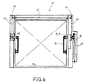
- Figure 6 illustrates an alternative embodiment of the drive device automatic in which a single geared motor 30 is provided.
- the order of movement transmission lever 16 provided on the lateral upright 12 opposite the one where the gear motor 30 is located is ensured by a chain transmission 42 and cogwheels 43.
- the latter can transmit the compensating force or the opposite axis rotation without spring on one side.
- the compensation mechanism 20 used in the overhead door 10 according to the invention is already known.
- Figure 5 which illustrates the tilting closure panel 15, in solid lines, in the intermediate position and, in broken lines, in the open position.
- This lever 16 is connected to the tilting closure panel 15 by a joint 18.
- This figure clearly illustrates the compensation mechanism 20.
- This the latter has two parallel springs 21 fixed at their lower ends to the lateral upright 12 and at their upper ends to the lever 16 beyond the axis of rotation 17.
- the motion transmission lever 16 is integral with a lever sliding 22 by an articulation 23, this lever carrying at its free end a roller roller 24 slidably mounted in a groove 25 provided on said closure panel tilting 15.
- This sliding lever 22 is integral with a connecting rod 26 by an articulation 27, this connecting rod being mounted on the lateral upright 12 by a hinge 28.
- the articulation 18 between the movement transmission lever 16 and the panel tilting shutter 15 describes an arc of circle A extending between A1 and A2
- the articulation 23 between the movement transmission lever 16 and the sliding lever 22 describes an arc of a circle B extending between B1 and B2
- the articulation 27 between the lever sliding 22 and the connecting rod 26 describes an arc of circle C between C1 and C2.
- the springs 21 transmit a lifting force at said tilting closure panel 15 by means of the levers transmission of movement 16.
- the sliding levers 22 follow the movement levers 16 45 ° in advance and cause the rod 26 to pivot.
- the roller 24 then moves in the groove 25 and restores the resistant moment of the panel tilting shutter 15 with that of the springs 21 throughout the maneuver.
- the roller 24 abuts in the bottom of the groove 25, the articulation 18 of the motion transmission lever 16 comes to position A2 and the joint 23 of the sliding lever 22 comes to position B2.
- the weight of the tilting panel 15 transmits to the sliding lever 22 a locking force.
- the B2 position of this sliding lever 22 being located beyond the axis of rotation 17 of the lever 16, the tilting shutter panel 15 is kept in balance by its own weight. In this position, the moment of equilibrium of the springs 21 is practically zero.
- the operation of the tilting door 10 according to the invention is described below.
- the tilting shutter panel 15 is in the closed position. To open it, the user controls the starting of the geared motors 30, 31 either by pressing directly on the corresponding button 34, either by means of its remote control.
- the rotation of geared motors 30, 31 instantly causes the rotation of the transmission levers 16 around their fixed axis of rotation 17.
- the mechanisms compensation 20 do not come into action, balancing the shutter panel 15 being provided directly by the gear motor 30, 31 via the levers 16.
- the tilting closure panel 15 arrives in the open position. At this time, the purposes of stroke of the gearmotors 30, 31 automatically cut off their power supply.
- the reverse operation closes the tilting shutter panel 15. In case of power failure for example, the handle 35 disengages the geared motors 30, 31 and manually operate the tilting closure panel 15. In this case, the compensation mechanisms 20 come into action to balance the panel shutter 15 by means of levers 16 and its axis of rotation 17.
- the tilting closure panel 15 is moved uniformly, without jerk, and is held laterally avoiding the risks of pitching.
Landscapes
- Power-Operated Mechanisms For Wings (AREA)
Description
- la figure 1 est une vue d'ensemble de face d'une entrée de garage équipée de la porte selon l'invention en position ouverte,
- la figure 2 est une vue de côté partielle de l'entrée de garage de la figure 1,
- la figure 3 est une vue éclatée du dispositif d'entraínement automatique,
- la figure 4 est une vue de dessus du dispositif de la figure 3 et la figure 4A est une vue de détail de l'arbre moteur,
- la figure 5 est une vue de côté d'un exemple de réalisation du mécanisme de compensation, et
- la figure 6 est une vue similaire à la figure 1 d'une variante de réalisation.
Claims (9)
- Porte basculante (10) motorisée à ressorts latéraux ou pistons à gaz, notamment pour une ouverture de garage ou de tout autre local, du type à déplacement circulaire, cette porte comportant un cadre fixe (11) pourvu au moins de deux montants latéraux fixes (12) disposés de part et d'autre de ladite ouverture, un panneau d'obturation basculant (15) monté entre les deux montants, au moins un levier de transmission de mouvement (16) couplé au panneau d'obturation basculant (15) par une articulation (18), ce levier comportant un axe de rotation (17) fixe monté en rotation dans le montant latéral correspondant et agencé pour imprimer audit panneau d'obturation basculant (15) un déplacement circulaire, l'articulation (18) décrivant un arc de cercle (A) ayant pour centre l'axe de rotation (17), au moins un mécanisme de compensation (20) comprenant des ressorts latéraux ou pistons à gaz, prévu dans le montant latéral correspondant et couplé audit levier (16), et au moins un dispositif d'entraínement automatique (30, 31) agencé pour manoeuvrer ledit panneau d'obturation basculant (15) et comprenant au moins un motoréducteur (30, 31), caractérisée en ce que ledit au moins motoréducteur (30, 31) est monté rigidement dans au moins un montant latéral fixe (12) de manière à former avec ladite porte un ensemble fini monobloc prêt à poser, en ce qu'il est pourvu d'un arbre moteur traversant (37), aligné avec l'axe de rotation (17) du levier de transmission de mouvement (16) et en ce que ledit axe de rotation (17) est formé de deux parties distinctes directement couplées aux deux extrémités de l'arbre moteur (37) au moyen d'accouplements positifs (38), l'une des parties étant couplée audit panneau d'obturation basculant (15) et l'autre des parties étant en prise directe avec le mécanisme de compensation (20).
- Porte basculante selon la revendication 1, caractérisée en ce que les deux parties de l'axe de rotation (17) du levier de transmission de mouvement (16) comportent chacune à leur extrémité une douille (38) agencée pour recevoir l'extrémité correspondante dudit arbre moteur (37).
- Porte basculante selon la revendication 2, caractérisée en ce que l'accouplement positif comporte les extrémités dudit arbre moteur (37) dont la section est non circulaire et les douilles (38) dudit levier de transmission de mouvement (16) dont la section est complémentaire à celle des extrémités de l'arbre moteur.
- Porte basculante selon l'une quelconque des revendications précédentes, caractérisée en ce que le dispositif d'entraínement automatique comporte deux motoréducteurs (30, 31) montés rigidement dans chaque montant latéral fixe (12) et couplés à chaque levier de transmission de mouvement (16).
- Porte basculante selon la revendication 4, caractérisée en ce que les deux motoréducteurs (30, 31) sont raccordés électriquement l'un à l'autre de manière à fonctionner en synchronisme, les câbles et prises correspondants étant disposés dans ledit cadre fixe (11).
- Porte basculante selon l'une quelconque des revendications précédentes, caractérisée en ce que le dispositif d'entraínement automatique comporte un motoréducteur (30) couplé à un premier levier de transmission de mouvement (16) et une transmission par chaínes (42) et roues dentées (43) agencée pour entraíner le second levier de transmission de mouvement (16).
- Porte basculante selon l'une quelconque des revendications précédentes 1 à 5, caractérisée en ce que le dispositif d'entraínement automatique comporte un motoréducteur (30) couplé à un premier levier de transmission de mouvement (16) et une transmission par poulies et courroies agencée pour entraíner le second levier de transmission de mouvement (16).
- Porte basculante selon l'une quelconque des revendications précédentes, caractérisée en ce que ledit au moins motoréducteur (30, 31) comporte une poignée de débrayage (35) agencée pour permettre un fonctionnement de ladite porte en mode manuel.
- Porte basculante selon l'une quelconque des revendications précédentes, caractérisée en ce que ledit au moins motoréducteur (30, 31) comporte un boítier de commande électronique (32) branché sur le secteur par un câble et une prise (33).
Applications Claiming Priority (2)
| Application Number | Priority Date | Filing Date | Title |
|---|---|---|---|
| FR9805350 | 1998-04-24 | ||
| FR9805350A FR2777935B1 (fr) | 1998-04-24 | 1998-04-24 | Porte basculante motorisee a ressorts lateraux ou pistons a gaz |
Publications (2)
| Publication Number | Publication Date |
|---|---|
| EP0952293A1 EP0952293A1 (fr) | 1999-10-27 |
| EP0952293B1 true EP0952293B1 (fr) | 2002-07-03 |
Family
ID=9525790
Family Applications (1)
| Application Number | Title | Priority Date | Filing Date |
|---|---|---|---|
| EP19990440089 Expired - Lifetime EP0952293B1 (fr) | 1998-04-24 | 1999-04-23 | Porte basculante motorisee a ressorts lateraux ou pistons a gaz du type a deplacement circulaire |
Country Status (3)
| Country | Link |
|---|---|
| EP (1) | EP0952293B1 (fr) |
| DE (1) | DE69901981D1 (fr) |
| FR (1) | FR2777935B1 (fr) |
Families Citing this family (3)
| Publication number | Priority date | Publication date | Assignee | Title |
|---|---|---|---|---|
| FR2871189B1 (fr) * | 2004-06-08 | 2007-01-19 | Albert Moos | Dispositif d'entrainement automatique pour porte basculante du type a deplacement circulaire et porte basculante equipee d'un tel dispositif |
| FR2928168B1 (fr) * | 2008-02-29 | 2013-04-12 | Andre Remonato | Appareil sous forme de carter comprenant les mecanismes d'equilibrage, de pivotement et de suspension d'une porte basculante prevue a etre motorisee avec systeme de verrouillage et deverrouillage automatique a multifonctions. |
| US8590209B1 (en) * | 2012-09-27 | 2013-11-26 | The Chamberlain Group, Inc. | Air spring counterbalance |
Family Cites Families (6)
| Publication number | Priority date | Publication date | Assignee | Title |
|---|---|---|---|---|
| AT305822B (de) * | 1970-01-22 | 1973-03-12 | Doering Erich | Elektromotorischer Antrieb mit einem umsteuerbaren Elektromotor mit einem Untersetzungsgetriebe für ein Schwingtor, insbesondere Garagen-Schwingtor |
| FR2375418A1 (fr) * | 1976-12-21 | 1978-07-21 | Tubauto | Commande electromecanique pour porte basculante |
| FR2529250B1 (fr) * | 1982-06-29 | 1988-06-03 | Almatic Sa | Porte basculante motorisee |
| FR2696777B3 (fr) * | 1992-10-08 | 1995-03-24 | Henri Brunet | Porte basculante monobloc, à compensation régulée par des modules inverseurs de poussée, composés de ressorts à gaz, tous les éléments nécessaires au fonctionnement étant encastrés dans le cadre. |
| FR2734860B1 (fr) * | 1995-05-30 | 1997-07-25 | Trendel Et Fils A | Porte de garage basculante motorisee, disposant d'un compensateur de force variable |
| FR2744483B1 (fr) * | 1996-02-02 | 1998-06-12 | Novoferm France Sa | Porte a ouverture verticale |
-
1998
- 1998-04-24 FR FR9805350A patent/FR2777935B1/fr not_active Expired - Fee Related
-
1999
- 1999-04-23 EP EP19990440089 patent/EP0952293B1/fr not_active Expired - Lifetime
- 1999-04-23 DE DE69901981T patent/DE69901981D1/de not_active Expired - Lifetime
Also Published As
| Publication number | Publication date |
|---|---|
| EP0952293A1 (fr) | 1999-10-27 |
| FR2777935B1 (fr) | 2000-06-02 |
| DE69901981D1 (de) | 2002-08-08 |
| FR2777935A1 (fr) | 1999-10-29 |
Similar Documents
| Publication | Publication Date | Title |
|---|---|---|
| FR2742185A1 (fr) | Dispositif d'entree a ouverture automatique pour zone controlee | |
| EP0952293B1 (fr) | Porte basculante motorisee a ressorts lateraux ou pistons a gaz du type a deplacement circulaire | |
| EP3510227B1 (fr) | Fenêtre coulissante pour un bâtiment et installation domotique comprenant une telle fenêtre coulissante | |
| FR2598140A1 (fr) | Ascenseur pour le transport des personnes. | |
| FR2871189A1 (fr) | Dispositif d'entrainement automatique pour porte basculante du type a deplacement circulaire et porte basculante equipee d'un tel dispositif | |
| EP3418483A1 (fr) | Procédé de réglage d'un dispositif d'entraînement motorisé d'un portail battant | |
| EP0524900B1 (fr) | Dispositif de commande électromécanique pour porte basculante, notamment pour porte basculante de garage | |
| FR2707695A1 (fr) | Portail à mouvements d'ouverture et de fermeture motorisés. | |
| FR2591650A1 (fr) | Dispositif de manoeuvre pour volets ou persiennes a un ou deux vantaux pivotants | |
| EP0089909B1 (fr) | Dispositif de commande électromécanique pour porte basculante | |
| FR3094077A1 (fr) | Volet de désenfumage à portillon et système d’évacuation comprenant un tel volet | |
| EP3190253B1 (fr) | Fenêtre oscillo-battante pour un bâtiment et installation domotique comprenant une telle fenêtre oscillo-battante | |
| EP0477068B1 (fr) | Système de désenfumage pour façades de bâtiment | |
| EP3333349B1 (fr) | Fenêtre oscillo-battante pour un bâtiment, installation domotique comprenant une telle fenêtre et procédé de commande en fonctionnement d'un dispositif d'entraînement motorisé d'une telle fenêtre | |
| EP1050656B1 (fr) | Portail automatique à vantail rotatif | |
| FR2947294A3 (fr) | Dispositif de fermeture d'une baie constituee par une porte sectionnelle, et procede de montage pour le mettre en oeuvre | |
| FR3053073A1 (fr) | Installation domotique et procede de mise en service de ladite installation | |
| FR2529250A1 (fr) | Porte basculante motorisee | |
| FR2819502A1 (fr) | Systeme et dispositif de deplacement d'un element pesant | |
| EP0028973A1 (fr) | Dispositif pour assurer la manoeuvre d'une porte basculante et porte ainsi équipée | |
| EP1541794B1 (fr) | Dispositif d'entraînement de porte de garage | |
| EP0945585B1 (fr) | Volet roulant comportant un dispositif d'entrainement manuel | |
| EP1283322A1 (fr) | Dispositif de manoeuvre d'une porte basculante | |
| FR2973430A1 (fr) | Volet coulissant pour l'occultation d'ouvertures dans des facades d'immeubles industriels ou d'habitation | |
| FR2750447A1 (fr) | Dispositif de commande electromecanique pour porte basculante, notamment porte de garage |
Legal Events
| Date | Code | Title | Description |
|---|---|---|---|
| PUAI | Public reference made under article 153(3) epc to a published international application that has entered the european phase |
Free format text: ORIGINAL CODE: 0009012 |
|
| AK | Designated contracting states |
Kind code of ref document: A1 Designated state(s): BE CH DE ES FR IT LI LU |
|
| AX | Request for extension of the european patent |
Free format text: AL;LT;LV;MK;RO;SI |
|
| 17P | Request for examination filed |
Effective date: 20000408 |
|
| AKX | Designation fees paid |
Free format text: BE CH DE ES FR IT LI LU |
|
| 17Q | First examination report despatched |
Effective date: 20010118 |
|
| GRAG | Despatch of communication of intention to grant |
Free format text: ORIGINAL CODE: EPIDOS AGRA |
|
| GRAG | Despatch of communication of intention to grant |
Free format text: ORIGINAL CODE: EPIDOS AGRA |
|
| GRAH | Despatch of communication of intention to grant a patent |
Free format text: ORIGINAL CODE: EPIDOS IGRA |
|
| GRAH | Despatch of communication of intention to grant a patent |
Free format text: ORIGINAL CODE: EPIDOS IGRA |
|
| 111L | Licence recorded |
Free format text: 20011002 0100 ETABLISSEMENTS A MOOS SARL |
|
| GRAH | Despatch of communication of intention to grant a patent |
Free format text: ORIGINAL CODE: EPIDOS IGRA |
|
| GRAA | (expected) grant |
Free format text: ORIGINAL CODE: 0009210 |
|
| AK | Designated contracting states |
Kind code of ref document: B1 Designated state(s): BE CH DE ES FR IT LI LU |
|
| PG25 | Lapsed in a contracting state [announced via postgrant information from national office to epo] |
Ref country code: IT Free format text: LAPSE BECAUSE OF FAILURE TO SUBMIT A TRANSLATION OF THE DESCRIPTION OR TO PAY THE FEE WITHIN THE PRESCRIBED TIME-LIMIT;WARNING: LAPSES OF ITALIAN PATENTS WITH EFFECTIVE DATE BEFORE 2007 MAY HAVE OCCURRED AT ANY TIME BEFORE 2007. THE CORRECT EFFECTIVE DATE MAY BE DIFFERENT FROM THE ONE RECORDED. Effective date: 20020703 |
|
| REG | Reference to a national code |
Ref country code: CH Ref legal event code: EP |
|
| REF | Corresponds to: |
Ref document number: 69901981 Country of ref document: DE Date of ref document: 20020808 |
|
| PG25 | Lapsed in a contracting state [announced via postgrant information from national office to epo] |
Ref country code: DE Free format text: LAPSE BECAUSE OF FAILURE TO SUBMIT A TRANSLATION OF THE DESCRIPTION OR TO PAY THE FEE WITHIN THE PRESCRIBED TIME-LIMIT Effective date: 20021005 |
|
| PG25 | Lapsed in a contracting state [announced via postgrant information from national office to epo] |
Ref country code: ES Free format text: LAPSE BECAUSE OF FAILURE TO SUBMIT A TRANSLATION OF THE DESCRIPTION OR TO PAY THE FEE WITHIN THE PRESCRIBED TIME-LIMIT Effective date: 20030130 |
|
| PG25 | Lapsed in a contracting state [announced via postgrant information from national office to epo] |
Ref country code: LU Free format text: LAPSE BECAUSE OF NON-PAYMENT OF DUE FEES Effective date: 20030423 |
|
| PG25 | Lapsed in a contracting state [announced via postgrant information from national office to epo] |
Ref country code: LI Free format text: LAPSE BECAUSE OF NON-PAYMENT OF DUE FEES Effective date: 20030430 Ref country code: CH Free format text: LAPSE BECAUSE OF NON-PAYMENT OF DUE FEES Effective date: 20030430 Ref country code: BE Free format text: LAPSE BECAUSE OF NON-PAYMENT OF DUE FEES Effective date: 20030430 |
|
| PLBE | No opposition filed within time limit |
Free format text: ORIGINAL CODE: 0009261 |
|
| STAA | Information on the status of an ep patent application or granted ep patent |
Free format text: STATUS: NO OPPOSITION FILED WITHIN TIME LIMIT |
|
| 26N | No opposition filed |
Effective date: 20030404 |
|
| BERE | Be: lapsed |
Owner name: *MOOS ALBERT Effective date: 20030430 |
|
| REG | Reference to a national code |
Ref country code: CH Ref legal event code: PL |
|
| REG | Reference to a national code |
Ref country code: FR Ref legal event code: CL |
|
| REG | Reference to a national code |
Ref country code: FR Ref legal event code: PLFP Year of fee payment: 18 |
|
| REG | Reference to a national code |
Ref country code: FR Ref legal event code: PLFP Year of fee payment: 19 |
|
| REG | Reference to a national code |
Ref country code: FR Ref legal event code: PLFP Year of fee payment: 20 |
|
| PGFP | Annual fee paid to national office [announced via postgrant information from national office to epo] |
Ref country code: FR Payment date: 20180423 Year of fee payment: 20 |