EP0952288B1 - Locking device - Google Patents
Locking device Download PDFInfo
- Publication number
- EP0952288B1 EP0952288B1 EP19980105567 EP98105567A EP0952288B1 EP 0952288 B1 EP0952288 B1 EP 0952288B1 EP 19980105567 EP19980105567 EP 19980105567 EP 98105567 A EP98105567 A EP 98105567A EP 0952288 B1 EP0952288 B1 EP 0952288B1
- Authority
- EP
- European Patent Office
- Prior art keywords
- plate
- striker
- locking
- locking device
- pressing plate
- Prior art date
- Legal status (The legal status is an assumption and is not a legal conclusion. Google has not performed a legal analysis and makes no representation as to the accuracy of the status listed.)
- Expired - Lifetime
Links
Images







Classifications
-
- B—PERFORMING OPERATIONS; TRANSPORTING
- B60—VEHICLES IN GENERAL
- B60N—SEATS SPECIALLY ADAPTED FOR VEHICLES; VEHICLE PASSENGER ACCOMMODATION NOT OTHERWISE PROVIDED FOR
- B60N2/00—Seats specially adapted for vehicles; Arrangement or mounting of seats in vehicles
- B60N2/24—Seats specially adapted for vehicles; Arrangement or mounting of seats in vehicles for particular purposes or particular vehicles
- B60N2/32—Seats specially adapted for vehicles; Arrangement or mounting of seats in vehicles for particular purposes or particular vehicles convertible for other use
- B60N2/36—Seats specially adapted for vehicles; Arrangement or mounting of seats in vehicles for particular purposes or particular vehicles convertible for other use into a loading platform
- B60N2/366—Seats specially adapted for vehicles; Arrangement or mounting of seats in vehicles for particular purposes or particular vehicles convertible for other use into a loading platform characterised by the locking device
-
- E—FIXED CONSTRUCTIONS
- E05—LOCKS; KEYS; WINDOW OR DOOR FITTINGS; SAFES
- E05B—LOCKS; ACCESSORIES THEREFOR; HANDCUFFS
- E05B15/00—Other details of locks; Parts for engagement by bolts of fastening devices
- E05B15/0006—Devices for aligning wing and frame; Anti-rattling devices
-
- E—FIXED CONSTRUCTIONS
- E05—LOCKS; KEYS; WINDOW OR DOOR FITTINGS; SAFES
- E05B—LOCKS; ACCESSORIES THEREFOR; HANDCUFFS
- E05B77/00—Vehicle locks characterised by special functions or purposes
- E05B77/36—Noise prevention; Anti-rattling means
- E05B77/38—Cushion elements, elastic guiding elements or holding elements, e.g. for cushioning or damping the impact of the bolt against the striker during closing of the wing
-
- E—FIXED CONSTRUCTIONS
- E05—LOCKS; KEYS; WINDOW OR DOOR FITTINGS; SAFES
- E05B—LOCKS; ACCESSORIES THEREFOR; HANDCUFFS
- E05B83/00—Vehicle locks specially adapted for particular types of wing or vehicle
- E05B83/16—Locks for luggage compartments, car boot lids or car bonnets
-
- E—FIXED CONSTRUCTIONS
- E05—LOCKS; KEYS; WINDOW OR DOOR FITTINGS; SAFES
- E05B—LOCKS; ACCESSORIES THEREFOR; HANDCUFFS
- E05B85/00—Details of vehicle locks not provided for in groups E05B77/00 - E05B83/00
- E05B85/20—Bolts or detents
- E05B85/24—Bolts rotating about an axis
- E05B85/243—Bolts rotating about an axis with a bifurcated bolt
-
- Y—GENERAL TAGGING OF NEW TECHNOLOGICAL DEVELOPMENTS; GENERAL TAGGING OF CROSS-SECTIONAL TECHNOLOGIES SPANNING OVER SEVERAL SECTIONS OF THE IPC; TECHNICAL SUBJECTS COVERED BY FORMER USPC CROSS-REFERENCE ART COLLECTIONS [XRACs] AND DIGESTS
- Y10—TECHNICAL SUBJECTS COVERED BY FORMER USPC
- Y10T—TECHNICAL SUBJECTS COVERED BY FORMER US CLASSIFICATION
- Y10T292/00—Closure fasteners
- Y10T292/08—Bolts
- Y10T292/0801—Multiple
- Y10T292/0848—Swinging
- Y10T292/0849—Operating means
- Y10T292/0853—Link and lever
-
- Y—GENERAL TAGGING OF NEW TECHNOLOGICAL DEVELOPMENTS; GENERAL TAGGING OF CROSS-SECTIONAL TECHNOLOGIES SPANNING OVER SEVERAL SECTIONS OF THE IPC; TECHNICAL SUBJECTS COVERED BY FORMER USPC CROSS-REFERENCE ART COLLECTIONS [XRACs] AND DIGESTS
- Y10—TECHNICAL SUBJECTS COVERED BY FORMER USPC
- Y10T—TECHNICAL SUBJECTS COVERED BY FORMER US CLASSIFICATION
- Y10T292/00—Closure fasteners
- Y10T292/08—Bolts
- Y10T292/0862—Swinging and hooked end, multiple head
-
- Y—GENERAL TAGGING OF NEW TECHNOLOGICAL DEVELOPMENTS; GENERAL TAGGING OF CROSS-SECTIONAL TECHNOLOGIES SPANNING OVER SEVERAL SECTIONS OF THE IPC; TECHNICAL SUBJECTS COVERED BY FORMER USPC CROSS-REFERENCE ART COLLECTIONS [XRACs] AND DIGESTS
- Y10—TECHNICAL SUBJECTS COVERED BY FORMER USPC
- Y10T—TECHNICAL SUBJECTS COVERED BY FORMER US CLASSIFICATION
- Y10T292/00—Closure fasteners
- Y10T292/08—Bolts
- Y10T292/1043—Swinging
- Y10T292/1044—Multiple head
- Y10T292/1045—Operating means
- Y10T292/1047—Closure
-
- Y—GENERAL TAGGING OF NEW TECHNOLOGICAL DEVELOPMENTS; GENERAL TAGGING OF CROSS-SECTIONAL TECHNOLOGIES SPANNING OVER SEVERAL SECTIONS OF THE IPC; TECHNICAL SUBJECTS COVERED BY FORMER USPC CROSS-REFERENCE ART COLLECTIONS [XRACs] AND DIGESTS
- Y10—TECHNICAL SUBJECTS COVERED BY FORMER USPC
- Y10T—TECHNICAL SUBJECTS COVERED BY FORMER US CLASSIFICATION
- Y10T292/00—Closure fasteners
- Y10T292/08—Bolts
- Y10T292/1043—Swinging
- Y10T292/1075—Operating means
- Y10T292/1083—Rigid
- Y10T292/1092—Swinging catch
Definitions
- the present invention relates to a locking device according to the preamble part of the independent claim 1 for locking a vehicle door, an engine hood, a trunk lid, a reclining seat back, and the like.
- the vehicle has an opening/closing door, an engine hood, a trunk lid, a reclining seat back, and the like.
- the locking device is used for locking those components.
- An example of the rear seat of an automobile or a motor car of the sedan type is schematically illustrated in Fig. 20.
- the rear seat back is divided into two sections 1L and 1R, and those divided rear backs may be turned down onto the seat cushion 2 independently.
- An opening 3 is formed in the rear floor pan partitioning the trunk room. When the divided rear seat backs 1L and 1R are turned down to the seat cushion 2, the trunk room is opened into the inside of the car.
- the divided rear seat back 1L or 1R is turned down onto the seat cushion 2, and the long baggage is placed stretching over both the rear seat space and the trunk room.
- a striker 4 shaped like a bent rod is attached to the rear seat back or the car body.
- a locking device 10 is attached to the seat back or the car body (not being attached with the striker).
- the striker 4 is attached to the car body, and the locking devices are attached to the rear seat backs 1L and 1R.
- a lock-removal knob 11 of the locking device 10 is operated to remove the locking of the locking device.
- a buffering member e.g., a cushion rubber pad
- the buffering member will lose its buffering function by aging or wear.
- the striker 4 plays when its function is reduced or lost.
- the locking device using the buffering member is difficult in maintaining its product quality for a long time.
- the striker pressing member is coaxially coupled into the locking plate for holding down the turn of the latch plate. Therefore, in manufacturing the locking device not requiring the striker pressing members and those requiring the same, it is difficult to increase a rate of the number of the component parts of the locking devices that may be used commonly for both types of the locking devices to the number of all the component parts thereof and it is difficult to reduce the manufacturing cost.
- the striker pressing member and the locking plate are coaxially assembled. Because of this, it is difficult to set the amount of turn of the striker pressing member as desired. To satisfactorily press the striker pressing member against the striker, it is necessary to use a spring having a large force to urge the striker pressing member against the striker.
- the striker pressing member is disposed such that its turning center lies offset from the line representative of the advancing direction of the striker. Therefore, to obtain a pressing force dependent on a load acting in the same direction as of a play of the striker, a larger spring force is required for the spring for urging the striker pressing member against the striker.
- GB 2 235 011 A discloses a motor vehicle door lock comprising a lock plate supporting a swivel latch, a catch, an actuating lever system and a catch guide.
- DE 16 53 994 A discloses a door lock for a vehicle, wherein the door lock comprises a main plate, an auxiliary plate, a latch, a catch and a wedge member.
- a locking device comprising a casing; a cover plate fastened to said casing into an unit construction; a latch plate for locking a striker, wherein said latch plate is rotatably supported by said casing and said cover plate; a locking plate being rotatably supported by said casing and said cover plate, wherein said locking plate locks said latch plate in its turn, thereby to ensure a locking of said striker by said latch plate; locking-state removal means for removing the locking of said striker by said latch plate by turning said locking plate; a striker pressing plate rotatably supported by said cover plate for pressing said striker against said latch plate in a state that said latch plate is locked in its turn; and a coupling means formed in said cover plate, wherein said coupling means pivotally supports a coupling part formed on said striker pressing plate, and said coupling means includes slip-off preventing means for preventing said coupling means and said coupling part from slipping off each other.
- the amount of turn of the striker pressing member is set as desired.
- said coupling means comprises a guide slit and a guide hole.
- said coupling part is a hook-like curved piece.
- said coupling means is U-shaped in cross section and said coupling part is a flange portion.
- a square spring stopper formed in said cover plate in which one end of a plate spring is put, and a spring receiving part formed at said striker pressing plate in which the other end of said plate spring is put.
- a turning center of said striker pressing plate lies on a line representative of an advancing direction of said striker.
- a cam face is provided on said locking plate and a further cam face is provided on said striker pressing plate respectively, so that said striker pressing plate rotates interlockingly with said locking plate.
- FIG. 1 showing an external appearance of the locking device
- Fig. 2 showing in exploded view of the structure of the locking device
- Fig. 3 showing the inner structure of the same
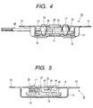
- Fig. 4 showing a cross sectional view taken along line IV-IV in Fig. 3
- Fig. 5 showing a cross sectional view taken along line V-V in Fig. 3.
- a frame-shaped casing 13 is provided with a couple of brackets 12 to be fastened to a frame (not shown) of a couple of rear seat backs 1L and 1R, and has a striker guide recess 14.
- a striker 4 may be moved into and out of the striker guide recess 14 (viz., moved in the upward and downward directions in Fig. 3).
- a cover plate 15 overlies the casing 13.
- a latch plate 16 is pivotally supported by a latch-plate support shaft 17 in a space between the casing 13 and the cover plate 15.
- a locking plate 19 is pivotally supported by a locking-plate support shaft 18, oriented parallel to the latch-plate support shaft 17.
- the latch-plate support shaft 17 and the locking-plate support shaft 18 are caulked at their extreme ends onto the casing 13 and the cover plate 15.
- a space is present between the combination of the latch plate 16 and the locking plate 19, and the cover plate 15.
- a striker pressing plate 20 is pivotally supported by a striker pressing plate support shaft 21, which is oriented parallel to in the latch-plate support shaft 17 and the locking-plate support shaft 18.
- One end of the support shaft 21 is engaged with the striker pressing plate 20, while the other end is caulked onto the cover plate 15.
- the support shaft 21 lies on a prolongation from a line extending in the longitudinal direction (vertical direction in Fig. 3) of the striker guide recess 14 so that the axial line of the striker pressing plate support shaft 21 lies on a prolongation from a line representative of the advancing direction of the striker 4.
- the latch plate 16 includes a stopper part 22, a protruded part 24, a striker receiving recess 25, and a spring receiving part 27.
- the stopper part 22 is to be brought into contact with the opening end of the striker guide recess 14 of the casing 13.
- the protruded part 24 includes an engaging part 23 which will engage with the locking plate 19 when assembled.
- the striker receiving recess 25 for receiving the striker 4 is located between the engaging part 23 and the stopper part 22.
- the spring receiving part 27 is used for fixing a return spring 26.
- the locking plate 19 includes an engaging part 28 which may engage with the engaging part 23 of the latch plate 16.
- the base of a lock-removal rod 29 is rotatably coupled with the locking plate 19 having the engaging part 28.
- the lock-removal knob 11 (Fig. 20) is fastened to the tip of the lock-removal rod 29 by means of screw means.
- the other end of the return spring 26 is coupled to the base of the lock-removal rod 29. A pulling force developed by the return spring 26 urges the latch plate 16 to turn about the latch-plate support shaft 17 counterclockwise (Fig. 3), and it urges the locking plate 19 to turn about the locking-plate support shaft 18 clockwise in (Fig. 3).
- the locking plate 19 and the striker pressing plate 20 are coupled with each other by a link member 30 interposed therebetween.
- One end of the link member 30 is rotatably coupled with the locking plate 19, while the other end is slidably placed in an elongated hole 31 formed in the striker pressing plate 20.
- the striker pressing plate 20 moves with the turning of the locking plate 19, while allowing the other end of the link member 30 to move along and within the elongated hole 31.
- a protruded piece 32 is protruded from one end of the link member 30 toward the cover plate 15, and its tip is located close to the cover plate 15 when assembled.
- the protruded piece 32 is used for preventing the link member 30 from slipping off from the locking plate 19 and the striker pressing plate 20.
- a twisted, coiled spring 33 is applied to the latch-plate support shaft 17, which is disposed between the latch plate 16 and the cover plate 15.
- the coiled spring 33 is fixed at one end to the cover plate 15 and at the other end to the striker pressing plate 20.
- the spring force of the coiled spring 33 urges the striker pressing plate 20 to turn about the support shaft 21 counterclockwise.
- the striker pressing plate 20 includes a surface portion 34 against which the striker 4 abuts. A distance from the support shaft 21 to the surface portion 34 gradually increases in the clockwise direction.
- the cover plate 15 has a striker receiving recess 35 at a location where it faces the striker guide recess 14.
- a bumper rubber piece 36 is fit into the striker receiving recess 35 as a buffering means.
- the striker 4 goes into the striker receiving recess 25 and abuts against the bumper rubber piece 36; the striker 4 further advances by inertia; the protruded part 24 of the latch plate 16 slips off from the engaging part 28 of the locking plate 19; the locking plate 19 is turned clockwise by the spring force of the return spring 26 by a distance corresponding to a movement of the other end of the link member 30 along and within the elongated hole 31; and the assembly of the locking device is put in a state as shown in Fig. 7.
- the spring force of the return spring 26 turns the latch plate 16 counterclockwise, and the engaging part 28 of the locking plate 19 is brought into engagement with the engaging part 23. The result is that the latch plate 16 is locked in its turn as shown in Fig. 8.
- the spring force of the coiled spring 33 By the spring force of the coiled spring 33, the surface portion 34 of the striker pressing plate 20 is brought into contact with the striker 4. The result is that the striker 4 is firmly held between the surface portion 34 of the striker pressing plate 20 and the striker receiving recess 25 of the lutch plate 16, eliminating a play of the striker 4.
- the lock-removal rod 29 is pulled to the left in Fig. 8 by operating the lock removal knob 11; the locking plate 19 is forcibly turned counterclockwise while resisting the spring forces of the return spring 26 and the coiled spring 33; the locking plate 19 is further turned from its position shown in Fig. 6 in the counterclockwise direction; and the latch plate 16 is turned counterclockwise by the return spring 26 to purge the striker 4 out of the striker guide recess 14.
- the striker pressing plate 20 is attached to the cover plate 15. Therefore, in manufacturing locking devices not using the striker pressing plate 20, only the cover plate 15 is altered. while the remaining component parts remains unchanged. This fact accrues to the manufacturing cost reduction. Further, the locking plate 19 and the striker pressing plate 20 are coupled with each other by the utilization of the link member 30. Because of this structural feature, the amount of turn of the striker pressing plate 20 may be selected, as desired, with respect to the amount of turn of the locking plate 19. The result is an increase of design freedom, e.g., improvement of the pressing force applied to the striker 4. Further, it is noted that the support shaft 21 is placed on the line prolonged from the line of the advancing direction of striker 4.
- the locking device can efficiently exercise its locking function to the striker 4. Furthermore, it is noted that a distance from the support shaft 21 to the surface portion 34 gradually increases in the direction of turning the striker pressing plate 20 by the spring force of the coiled spring 33. If the surface portion 34 is worn, the new surface portion 34 is pressed against the striker 4, producing no play of the striker 4.
- the striker pressing plate 20 is pivotally supported with respect to the cover plate 15, with the aid of the striker pressing support shaft 21 that is caulked onto the cover plate 15.
- the fitting portion corresponding to the support shaft 21 may be molded in one-piece construction by plastic working, e.g., burring working. By so doing, the number of parts required for the assembly of the locking device is reduced.
- FIG. 9 showing an external appearance of the locking device of the preferred embodiment
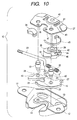
- Fig. 10 showing in exploded form the structure of the locking device
- Fig. 11 showing the inner structure of the same
- Fig. 12 showing a cross sectional view taken along line XII-XII in Fig. 11.
- a cover plate 37 has an engaging protrusion 40 formed by burring process.
- the protrusion 40 is to tightly be fit into a bore 39 of a striker pressing plate 38.
- An arcuate guide slit 41 is formed in the cover plate 37 while being located close to and along the engaging protrusion 40.
- One end of the arcuate guide slit 41 is somewhat enlarged to provide a guide hole 43. This hole receives a hook-like curved piece 42 as a tip of an engaging shaft 44 protruded from the striker pressing plate 38.
- the engaging shaft 44 having the curved piece 42 at its tip stands erect on the striker pressing plate 38.
- the shaft 44 is inserted into the arcuate guide slit 41 and movable along the arcuate guide slit 41.
- the striker pressing plate 38 includes a spring receiving part 46 for receiving one end of an arcuate plate spring 45.
- the one end of the arcuate plate spring 45 is held between the spring receiving part 46 and the cover plate 37.
- the plate spring 45 corresponds to the coiled spring 33 in the first embodiment.
- the other end of the plate spring 45 is put in a square spring stopper 47 of the cover plate 37.
- the striker pressing plate 38 and the plate spring 45 To temporarily assemble the cover plate 37, the striker pressing plate 38 and the plate spring 45, the one end of the plate spring 45 is put on the spring receiving part 46 of the striker pressing plate 38; the curved piece 42 is aligned with the guide hole 43; in this state, the engaging protrusion 40 of the cover plate 37 is inserted into the bore 39. The result is that the curved piece 42 is projected above the surface of the cover plate 37, while its base part, or the engaging shaft 44, passes through the guide hole 43 of the cover plate 37. In this state, the striker pressing plate 38 is turned and the other end of the plate spring 45 is put in the square spring stopper 47 of the cover plate 37.
- the second embodiment improves over the first embodiment in the workability in manufacturing the locking device 10.
- the present embodiment is designed such that a locking plate 48 and the striker pressing plate 38 interactively turn within a predetermined region.
- the engaging shaft 44 and the striker pressing plate 38 include cam faces 49 and 50.
- the cam face 50 of the striker pressing plate 38 follows, in motion, the cam face 49 of the locking plate 48. Provision of those cam faces 49 and 50 eliminates the necessity of the link member 30 used in the first embodiment in the device design. This technical feature produces many beneficial results: reduction of the number of required component parts and cost to manufacture, and simplification of assembling work.
- the striker 4 goes into the striker receiving recess 25 and abuts against the bumper rubber piece 36; the striker 4 further advances by inertia; the protruded part 24 of the latch plate 16 slips off from the engaging part 28 of the locking plate 48; the locking plate 48 is turned clockwise by the spring force of the return spring 26; and the assembly of the locking device is put in a state as shown in Fig. 14.
- the spring force of the return spring 26 turns the latch plate 16 counterclockwise, and the engaging part 28 of the locking plate 48 is brought into engagement with the engaging part 23.
- the result is that the latch plate 16 is locked in its turn as shown in Fig. 15.
- the plate spring 45 By the spring force of the plate spring 45, the surface portion 34 of the striker pressing plate 38 is brought into contact with the striker 4.
- the result is that the striker 4 is firmly held between the surface portion 34 of the striker pressing plate 38 and the striker receiving recess 25 of the lutch plate 16, eliminating a play of the striker 4.
- the lock-removal rod 29 is pulled to the left in Fig. 15 by operating the lock removal knob 11; the locking plate 48 is forcibly turned counterclockwise while resisting the spring forces of the return spring 26 and the plate spring 45; the locking plate 48 is further turned from its position shown in Fig. 13 in the counterclockwise direction; and the lutch plate 16 is turned counterclockwise by the return spring 26 to purge the striker 4 out of the striker guide recess 14.
- the engaging protrusion 40 is formed on the cover plate 37, and the bore 39 is formed in the striker pressing plate 38. It is evident that the engaging protrusion 40 may be formed on the striker pressing plate 38, and the bore 39 may be formed on the cover plate 37.
- FIG. 16 showing a plan view of the locking device of the preferred embodiment
- Fig. 17 showing a cross sectional view taken along line XVII-XVII in Fig. 16, and Figs. 18 and 19 showing plan views of a striker pressing plate and a cover plate.
- like reference numerals are used for designating like or equivalent portions in the embodiments previously described.
- a bore 54 is formed in a cover plate 51.
- An engaging protrusion 53 is formed on the striker pressing plate 52.
- the engaging protrusion 53 is slidably put in the bore 54.
- the cover plate 51 includes a portion 56 shaped like U in cross section.
- a flange portion 55 of the striker pressing plate 52 is put into the U-shaped portion 56 and fastened therewith.
- the flange portion 55 and the U-shaped portion 56 form slip-off preventing means.
- the curved piece 42 of the striker pressing plate 38 has the function corresponding to that of the U-shaped portion 56.
- the striker pressing plate 52 of this preferred embodiment is simply manufactured by plastic working. Therefore, the cost to manufacture is reduced.
- the striker pressing plate is included in the cover plate.
- most of the component parts of the locking device using the striker pressing plate are used, without any modification, for assembling a locking device not using the striker pressing plate.
- the means for interactively turning the locking plate and the striker pressing plate preferably include cam faces formed on the locking plate and the striker pressing plate.
- the cover plate and the striker pressing plate preferably include coupling means by which those plates are rotatably coupled with each other. In this case, the number of parts required for the locking device is reduced, and the caulking work is not used. The result is that the cost to manufacture is reduced.
- the center of rotation of the locking plate is offset from that of the striker pressing plate and those plates are coupled with each other by means of the interactively turning means.
- the amount of turn of the striker pressing plate is advantageously adjusted as desired.
- a satisfactory urging force of the striker pressing plate is preferably secured if a spring of small spring force is used for the spring for urging the striker pressing plate.
- the locking device have such a construction that the urging means is held between the cover plate and the striker pressing plate, and that coupling means may be formed in the cover plate and on the striker pressing plate, and the coupling means include slip-off preventing means for preventing the coupling parts from slipping off one from the other.
- the cover plate, the striker pressing plate, and the urging means may be temporarily assembled in advance. A speedy device manufacturing is advantageously realized.
Landscapes
- Engineering & Computer Science (AREA)
- Aviation & Aerospace Engineering (AREA)
- Transportation (AREA)
- Mechanical Engineering (AREA)
- Lock And Its Accessories (AREA)
- Seats For Vehicles (AREA)
Description
- The present invention relates to a locking device according to the preamble part of the
independent claim 1 for locking a vehicle door, an engine hood, a trunk lid, a reclining seat back, and the like. - The vehicle has an opening/closing door, an engine hood, a trunk lid, a reclining seat back, and the like. The locking device is used for locking those components. An example of the rear seat of an automobile or a motor car of the sedan type is schematically illustrated in Fig. 20. The rear seat back is divided into two
sections seat cushion 2 independently. Anopening 3 is formed in the rear floor pan partitioning the trunk room. When the dividedrear seat backs seat cushion 2, the trunk room is opened into the inside of the car. To load the car with a long baggage, e.g., skis, that cannot be accommodated within the trunk room, the divided rear seat back 1L or 1R is turned down onto theseat cushion 2, and the long baggage is placed stretching over both the rear seat space and the trunk room. - In this type of the motor car, a
striker 4 shaped like a bent rod is attached to the rear seat back or the car body. Alocking device 10 is attached to the seat back or the car body (not being attached with the striker). In the illustrated case, thestriker 4 is attached to the car body, and the locking devices are attached to therear seat backs rear seat backs seat cushion 2, a lock-removal knob 11 of thelocking device 10 is operated to remove the locking of the locking device. - To suppress an impact generated when the
striker 4 is put into thelocking device 10 and prevent a play of thestriker 4 being locked, a buffering member, e.g., a cushion rubber pad, is generally assembled into the locking device. The buffering member will lose its buffering function by aging or wear. Thestriker 4 plays when its function is reduced or lost. Thus, the locking device using the buffering member is difficult in maintaining its product quality for a long time. - To cope with this problem, there is proposed a novel vehicular locking device which is provided with a striker pressing member which receives a thrust of the striker in a state that the latch plate being in press contact with the striker is held down in its turn.
- In the above locking device, the striker pressing member is coaxially coupled into the locking plate for holding down the turn of the latch plate. Therefore, in manufacturing the locking device not requiring the striker pressing members and those requiring the same, it is difficult to increase a rate of the number of the component parts of the locking devices that may be used commonly for both types of the locking devices to the number of all the component parts thereof and it is difficult to reduce the manufacturing cost.
- Also in the above device, the striker pressing member and the locking plate are coaxially assembled. Because of this, it is difficult to set the amount of turn of the striker pressing member as desired. To satisfactorily press the striker pressing member against the striker, it is necessary to use a spring having a large force to urge the striker pressing member against the striker.
- The striker pressing member is disposed such that its turning center lies offset from the line representative of the advancing direction of the striker. Therefore, to obtain a pressing force dependent on a load acting in the same direction as of a play of the striker, a larger spring force is required for the spring for urging the striker pressing member against the striker.
-
GB 2 235 011 A discloses a motor vehicle door lock comprising a lock plate supporting a swivel latch, a catch, an actuating lever system and a catch guide. - Furthermore,
DE 16 53 994 A discloses a door lock for a vehicle, wherein the door lock comprises a main plate, an auxiliary plate, a latch, a catch and a wedge member. - It is an objective of the present invention to improve a locking device as indicated above so as to efficiently generate the pressing force of the pressing member against the striker.
- According to the present invention, the objective is solved by a locking device comprising a casing; a cover plate fastened to said casing into an unit construction; a latch plate for locking a striker, wherein said latch plate is rotatably supported by said casing and said cover plate; a locking plate being rotatably supported by said casing and said cover plate, wherein said locking plate locks said latch plate in its turn, thereby to ensure a locking of said striker by said latch plate; locking-state removal means for removing the locking of said striker by said latch plate by turning said locking plate; a striker pressing plate rotatably supported by said cover plate for pressing said striker against said latch plate in a state that said latch plate is locked in its turn; and a coupling means formed in said cover plate, wherein said coupling means pivotally supports a coupling part formed on said striker pressing plate, and said coupling means includes slip-off preventing means for preventing said coupling means and said coupling part from slipping off each other.
- Advantageously, by the locking device the amount of turn of the striker pressing member is set as desired.
- According to a preferred embodiment, said coupling means comprises a guide slit and a guide hole.
- According to still a further preferred embodiment, said coupling part is a hook-like curved piece.
- According to another preferred embodiment, said coupling means is U-shaped in cross section and said coupling part is a flange portion.
- According to another preferred embodiment, a square spring stopper formed in said cover plate in which one end of a plate spring is put, and a spring receiving part formed at said striker pressing plate in which the other end of said plate spring is put.
- According to another preferred embodiment, a turning center of said striker pressing plate lies on a line representative of an advancing direction of said striker.
- According to another preferred embodiment, a cam face is provided on said locking plate and a further cam face is provided on said striker pressing plate respectively, so that said striker pressing plate rotates interlockingly with said locking plate.
- Further preferred embodiments of the present invention are laid down in the further subclaims.
- In the following, the present invention is explained in greater detail by means of several embodiments thereof in conjunction with the accompanying drawings, wherein:
- In the accompanying drawings:
- Fig. 1 is a perspective view showing an external appearance of a locking device which does not fall under the scope of the present invention;
- Fig. 2 is an exploded view showing the structure of the locking device in Fig. 1;
- Fig. 3 is a plan view showing the inner structure of the locking device in Fig. 1;
- Fig. 4 is a cross sectional view taken along line IV-IV in Fig. 3;
- Fig. 5 is a cross sectional view taken along line V-V in Fig. 3;
- Fig. 6 is a plan view showing the operation of the locking device in Fig. 3;
- Fig. 7 is a plan view showing the operation of the locking device in Fig. 3;
- Fig. 8 is a plan view showing the operation of the locking device in Fig. 3;
- Fig. 9 is a perspective view showing an external appearance of a locking device according to a preferred embodiment;
- Fig. 10 is an exploded view showing the structure of the locking device in Fig. 9;
- Fig. 11 is a plan view showing the inner structure of the locking device in Fig. 9;
- Fig. 12 is a cross sectional view taken along line XII-XII in.Fig. 11;
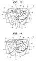
- Fig. 13 is a plan view showing the operation of the locking device in Fig. 11;
- Fig. 14 is a plan view showing the operation of the locking device in Fig. 11;
- Fig. 15 is a plan view showing the operation of the locking device in Fig. 11;
- Fig. 16 is a plan view showing a locking device according to a further preferred embodiment;
- Fig. 17 is a cross sectional view taken along line XVII-XVII in Fig. 16;
- Fig. 18 is a plan view showing a striker pressing plate used in the locking device in Fig. 16;
- Fig. 19 is a plan view showing a cover plate used in the locking device in Fig. 16; and
- Fig. 20 is a perspective view showing the inside of a vehicle equipped with a locking device.
-
- Here, it is stated that the embodiment as shown in figures 1 to 8 does not fall under the scope of the present invention and is still described in the detailed description in order to facilitate the understanding of the present invention. In the embodiment, the present invention is incorporated into the locking device for the reclining rear seat back already described with reference to Fig. 20.
- Reference is made to Fig. 1 showing an external appearance of the locking device, Fig. 2 showing in exploded view of the structure of the locking device, Fig. 3 showing the inner structure of the same, Fig. 4 showing a cross sectional view taken along line IV-IV in Fig. 3, and Fig. 5 showing a cross sectional view taken along line V-V in Fig. 3. A frame-
shaped casing 13 is provided with a couple ofbrackets 12 to be fastened to a frame (not shown) of a couple ofrear seat backs striker guide recess 14. Astriker 4 may be moved into and out of the striker guide recess 14 (viz., moved in the upward and downward directions in Fig. 3). - A
cover plate 15 overlies thecasing 13. Alatch plate 16 is pivotally supported by a latch-plate support shaft 17 in a space between thecasing 13 and thecover plate 15. Also in the space, a lockingplate 19 is pivotally supported by a locking-plate support shaft 18, oriented parallel to the latch-plate support shaft 17. The latch-plate support shaft 17 and the locking-plate support shaft 18 are caulked at their extreme ends onto thecasing 13 and thecover plate 15. - A space is present between the combination of the
latch plate 16 and the lockingplate 19, and thecover plate 15. In the space, astriker pressing plate 20 is pivotally supported by a striker pressingplate support shaft 21, which is oriented parallel to in the latch-plate support shaft 17 and the locking-plate support shaft 18. One end of thesupport shaft 21 is engaged with thestriker pressing plate 20, while the other end is caulked onto thecover plate 15. Thesupport shaft 21 lies on a prolongation from a line extending in the longitudinal direction (vertical direction in Fig. 3) of thestriker guide recess 14 so that the axial line of the striker pressingplate support shaft 21 lies on a prolongation from a line representative of the advancing direction of thestriker 4. - The
latch plate 16 includes astopper part 22, aprotruded part 24, astriker receiving recess 25, and aspring receiving part 27. Thestopper part 22 is to be brought into contact with the opening end of thestriker guide recess 14 of thecasing 13. Theprotruded part 24 includes anengaging part 23 which will engage with the lockingplate 19 when assembled. Thestriker receiving recess 25 for receiving thestriker 4 is located between theengaging part 23 and thestopper part 22. Thespring receiving part 27 is used for fixing areturn spring 26. - The locking
plate 19 includes anengaging part 28 which may engage with the engagingpart 23 of thelatch plate 16. The base of a lock-removal rod 29 is rotatably coupled with the lockingplate 19 having the engagingpart 28. The lock-removal knob 11 (Fig. 20) is fastened to the tip of the lock-removal rod 29 by means of screw means. The other end of thereturn spring 26 is coupled to the base of the lock-removal rod 29. A pulling force developed by thereturn spring 26 urges thelatch plate 16 to turn about the latch-plate support shaft 17 counterclockwise (Fig. 3), and it urges the lockingplate 19 to turn about the locking-plate support shaft 18 clockwise in (Fig. 3). - The locking
plate 19 and thestriker pressing plate 20 are coupled with each other by alink member 30 interposed therebetween. One end of thelink member 30 is rotatably coupled with the lockingplate 19, while the other end is slidably placed in anelongated hole 31 formed in thestriker pressing plate 20. Thestriker pressing plate 20 moves with the turning of the lockingplate 19, while allowing the other end of thelink member 30 to move along and within theelongated hole 31. - A protruded
piece 32 is protruded from one end of thelink member 30 toward thecover plate 15, and its tip is located close to thecover plate 15 when assembled. The protrudedpiece 32 is used for preventing thelink member 30 from slipping off from the lockingplate 19 and thestriker pressing plate 20. - A twisted, coiled
spring 33 is applied to the latch-plate support shaft 17, which is disposed between thelatch plate 16 and thecover plate 15. Thecoiled spring 33 is fixed at one end to thecover plate 15 and at the other end to thestriker pressing plate 20. The spring force of the coiledspring 33 urges thestriker pressing plate 20 to turn about thesupport shaft 21 counterclockwise. Thestriker pressing plate 20 includes asurface portion 34 against which thestriker 4 abuts. A distance from thesupport shaft 21 to thesurface portion 34 gradually increases in the clockwise direction. - The
cover plate 15 has astriker receiving recess 35 at a location where it faces thestriker guide recess 14. Abumper rubber piece 36 is fit into thestriker receiving recess 35 as a buffering means. - When the
striker 4, positioned as shown Fig. 3, is moved and goes into thestriker guide recess 14, thestriker 4 comes into contact with the engagingpart 23 of thelatch plate 16; thelatch plate 16 then starts to turn clockwise while resisting the spring force of thereturn spring 26; theprotruded part 24 of thelatch plate 16 is pressed against the engagingpart 28 of the lockingplate 19; the lockingplate 19 thereby starts to turn counterclockwise; and thestriker pressing plate 20 in turn starts to turn clockwise through thelink member 30. - As shown in Fig. 6, the
striker 4 goes into thestriker receiving recess 25 and abuts against thebumper rubber piece 36; thestriker 4 further advances by inertia; theprotruded part 24 of thelatch plate 16 slips off from the engagingpart 28 of the lockingplate 19; the lockingplate 19 is turned clockwise by the spring force of thereturn spring 26 by a distance corresponding to a movement of the other end of thelink member 30 along and within theelongated hole 31; and the assembly of the locking device is put in a state as shown in Fig. 7. - The spring force of the
return spring 26 turns thelatch plate 16 counterclockwise, and theengaging part 28 of the lockingplate 19 is brought into engagement with the engagingpart 23. The result is that thelatch plate 16 is locked in its turn as shown in Fig. 8. By the spring force of the coiledspring 33, thesurface portion 34 of thestriker pressing plate 20 is brought into contact with thestriker 4. The result is that thestriker 4 is firmly held between thesurface portion 34 of thestriker pressing plate 20 and thestriker receiving recess 25 of thelutch plate 16, eliminating a play of thestriker 4. - To remove the locking state of the
striker 4 by the locking device, the lock-removal rod 29 is pulled to the left in Fig. 8 by operating thelock removal knob 11; the lockingplate 19 is forcibly turned counterclockwise while resisting the spring forces of thereturn spring 26 and thecoiled spring 33; the lockingplate 19 is further turned from its position shown in Fig. 6 in the counterclockwise direction; and thelatch plate 16 is turned counterclockwise by thereturn spring 26 to purge thestriker 4 out of thestriker guide recess 14. - In the assembly of the locking device mentioned above, the
striker pressing plate 20 is attached to thecover plate 15. Therefore, in manufacturing locking devices not using thestriker pressing plate 20, only thecover plate 15 is altered. while the remaining component parts remains unchanged. This fact accrues to the manufacturing cost reduction. Further, the lockingplate 19 and thestriker pressing plate 20 are coupled with each other by the utilization of thelink member 30. Because of this structural feature, the amount of turn of thestriker pressing plate 20 may be selected, as desired, with respect to the amount of turn of the lockingplate 19. The result is an increase of design freedom, e.g., improvement of the pressing force applied to thestriker 4. Further, it is noted that thesupport shaft 21 is placed on the line prolonged from the line of the advancing direction ofstriker 4. When thestriker 4 plays, no rotation moment acts on thestriker pressing plate 20, although it is inevitably developed in the conventional locking device. Therefore, the locking device can efficiently exercise its locking function to thestriker 4. Furthermore, it is noted that a distance from thesupport shaft 21 to thesurface portion 34 gradually increases in the direction of turning thestriker pressing plate 20 by the spring force of the coiledspring 33. If thesurface portion 34 is worn, thenew surface portion 34 is pressed against thestriker 4, producing no play of thestriker 4. - In the embodiment, the
striker pressing plate 20 is pivotally supported with respect to thecover plate 15, with the aid of the striker pressingsupport shaft 21 that is caulked onto thecover plate 15. If required, the fitting portion corresponding to thesupport shaft 21 may be molded in one-piece construction by plastic working, e.g., burring working. By so doing, the number of parts required for the assembly of the locking device is reduced. - A preferred embodiment of the locking device according to the present invention will be described with reference to Figs. 9 through 15. In these figures, reference numerals are used for designating like or equivalent portions in the aforedescribed embodiment.
- Reference is made to Fig. 9 showing an external appearance of the locking device of the preferred embodiment, Fig. 10 showing in exploded form the structure of the locking device, Fig. 11 showing the inner structure of the same, and Fig. 12 showing a cross sectional view taken along line XII-XII in Fig. 11. A
cover plate 37 has an engagingprotrusion 40 formed by burring process. Theprotrusion 40 is to tightly be fit into abore 39 of astriker pressing plate 38. An arcuate guide slit 41 is formed in thecover plate 37 while being located close to and along the engagingprotrusion 40. One end of the arcuate guide slit 41 is somewhat enlarged to provide aguide hole 43. This hole receives a hook-likecurved piece 42 as a tip of an engagingshaft 44 protruded from thestriker pressing plate 38. - The engaging
shaft 44 having thecurved piece 42 at its tip stands erect on thestriker pressing plate 38. Theshaft 44 is inserted into the arcuate guide slit 41 and movable along the arcuate guide slit 41. Further, thestriker pressing plate 38 includes aspring receiving part 46 for receiving one end of anarcuate plate spring 45. The one end of thearcuate plate spring 45 is held between thespring receiving part 46 and thecover plate 37. Theplate spring 45 corresponds to thecoiled spring 33 in the first embodiment. The other end of theplate spring 45 is put in asquare spring stopper 47 of thecover plate 37. - To temporarily assemble the
cover plate 37, thestriker pressing plate 38 and theplate spring 45, the one end of theplate spring 45 is put on thespring receiving part 46 of thestriker pressing plate 38; thecurved piece 42 is aligned with theguide hole 43; in this state, the engagingprotrusion 40 of thecover plate 37 is inserted into thebore 39. The result is that thecurved piece 42 is projected above the surface of thecover plate 37, while its base part, or the engagingshaft 44, passes through theguide hole 43 of thecover plate 37. In this state, thestriker pressing plate 38 is turned and the other end of theplate spring 45 is put in thesquare spring stopper 47 of thecover plate 37. In turn thecurved piece 42 of the engagingshaft 44 is moved toward the arcuate guide slit 41, whereby thecover plate 37 and thestriker pressing plate 38 are coupled together, with theplate spring 45 being located therebetween. With such a temporarily assembling, the second embodiment improves over the first embodiment in the workability in manufacturing thelocking device 10. - The present embodiment is designed such that a locking
plate 48 and thestriker pressing plate 38 interactively turn within a predetermined region. To this end, the engagingshaft 44 and thestriker pressing plate 38 include cam faces 49 and 50. When the lockingplate 48 turns within the predetermined region, thecam face 50 of thestriker pressing plate 38 follows, in motion, thecam face 49 of the lockingplate 48. Provision of those cam faces 49 and 50 eliminates the necessity of thelink member 30 used in the first embodiment in the device design. This technical feature produces many beneficial results: reduction of the number of required component parts and cost to manufacture, and simplification of assembling work. - When the
striker 4, positioned as shown Fig. 11, is moved and goes into thestriker guide recess 14, thestriker 4 comes into contact with the engagingpart 23 of thelatch plate 16; thelatch plate 16 then starts to turn clockwise while resisting the spring force of thereturn spring 26; theprotruded part 24 of thelatch plate 16 is pressed against the engagingpart 28 of the lockingplate 48; the lockingplate 48 thereby starts to turn counterclockwise; and thestriker pressing plate 38 in turn starts to turn clockwise through the cam faces 49 and 50. - As shown in Fig. 13, the
striker 4 goes into thestriker receiving recess 25 and abuts against thebumper rubber piece 36; thestriker 4 further advances by inertia; theprotruded part 24 of thelatch plate 16 slips off from the engagingpart 28 of the lockingplate 48; the lockingplate 48 is turned clockwise by the spring force of thereturn spring 26; and the assembly of the locking device is put in a state as shown in Fig. 14. - The spring force of the
return spring 26 turns thelatch plate 16 counterclockwise, and theengaging part 28 of the lockingplate 48 is brought into engagement with the engagingpart 23. The result is that thelatch plate 16 is locked in its turn as shown in Fig. 15. By the spring force of theplate spring 45, thesurface portion 34 of thestriker pressing plate 38 is brought into contact with thestriker 4. The result is that thestriker 4 is firmly held between thesurface portion 34 of thestriker pressing plate 38 and thestriker receiving recess 25 of thelutch plate 16, eliminating a play of thestriker 4. - To remove the locking state of the
striker 4 by the locking device, the lock-removal rod 29 is pulled to the left in Fig. 15 by operating thelock removal knob 11; the lockingplate 48 is forcibly turned counterclockwise while resisting the spring forces of thereturn spring 26 and theplate spring 45; the lockingplate 48 is further turned from its position shown in Fig. 13 in the counterclockwise direction; and thelutch plate 16 is turned counterclockwise by thereturn spring 26 to purge thestriker 4 out of thestriker guide recess 14. - In the second embodiment, the engaging
protrusion 40 is formed on thecover plate 37, and thebore 39 is formed in thestriker pressing plate 38. It is evident that the engagingprotrusion 40 may be formed on thestriker pressing plate 38, and thebore 39 may be formed on thecover plate 37. - A locking device constructed according to another preferred embodiment will be described with reference to Figs. 16 through 19. Reference is made to Fig. 16 showing a plan view of the locking device of the preferred embodiment, Fig. 17 showing a cross sectional view taken along line XVII-XVII in Fig. 16, and Figs. 18 and 19 showing plan views of a striker pressing plate and a cover plate. In these figures, like reference numerals are used for designating like or equivalent portions in the embodiments previously described.
- A bore 54 is formed in a
cover plate 51. An engagingprotrusion 53 is formed on thestriker pressing plate 52. The engagingprotrusion 53 is slidably put in thebore 54. Thecover plate 51 includes aportion 56 shaped like U in cross section. Aflange portion 55 of thestriker pressing plate 52 is put into theU-shaped portion 56 and fastened therewith. Theflange portion 55 and theU-shaped portion 56 form slip-off preventing means. - In the second embodiment already described, the
curved piece 42 of thestriker pressing plate 38 has the function corresponding to that of theU-shaped portion 56. To manufacture the hook-likecurved piece 42, much and complicated work is consumed. However, advantageously thestriker pressing plate 52 of this preferred embodiment is simply manufactured by plastic working. Therefore, the cost to manufacture is reduced. - As seen from the foregoing description, the striker pressing plate is included in the cover plate. Advantageously, most of the component parts of the locking device using the striker pressing plate are used, without any modification, for assembling a locking device not using the striker pressing plate.
- In the construction of the locking device, the means for interactively turning the locking plate and the striker pressing plate preferably include cam faces formed on the locking plate and the striker pressing plate. Further, the cover plate and the striker pressing plate preferably include coupling means by which those plates are rotatably coupled with each other. In this case, the number of parts required for the locking device is reduced, and the caulking work is not used. The result is that the cost to manufacture is reduced.
- It is noted that the center of rotation of the locking plate is offset from that of the striker pressing plate and those plates are coupled with each other by means of the interactively turning means. With this structural feature, the amount of turn of the striker pressing plate is advantageously adjusted as desired. Further, a satisfactory urging force of the striker pressing plate is preferably secured if a spring of small spring force is used for the spring for urging the striker pressing plate.
- In the locking device in which the turning center of the striker pressing plate lies on the line representative of the advancing direction of the striker, a load acting in the same direction as of a play of the striker directly acts on the center of rotation of the striker pressing plate. Therefore, its durability and mechanical strength are improved, so that the locking of the striker is reliable.
- The locking device have such a construction that the urging means is held between the cover plate and the striker pressing plate, and that coupling means may be formed in the cover plate and on the striker pressing plate, and the coupling means include slip-off preventing means for preventing the coupling parts from slipping off one from the other. In this construction, the cover plate, the striker pressing plate, and the urging means may be temporarily assembled in advance. A speedy device manufacturing is advantageously realized.
Claims (7)
- A locking device comprising:characterized by a coupling means (41,43,56) formed in said cover plate (37,51), wherein said coupling means (41,43,56) pivotally supports a coupling part formed on said striker pressing plate (38,52), and said coupling means (41,43,56) includes slip-off preventing means for preventing said coupling means (41,43,56) and said coupling part from slipping off each other.a casing (13);a cover plate (37,51) fastened to said casing (13) into an unit construction;a latch plate (16) for locking a striker (4), wherein said latch plate (16) is rotatably supported by said casing (13) and said cover plate (37);a locking plate (48) being rotatably supported by said casing (13) and said cover plate (37,51), wherein said locking plate (48) locks said latch plate (16) in its turn, thereby to ensure a locking of said striker (4) by said latch plate (16);locking-state removal means for removing the locking of said striker (4) by said latch plate (16) by turning said locking plate (48); anda striker pressing plate (38,52) rotatably supported by said cover plate (37,51) for pressing said striker (4) against said latch plate (16) in a state that said latch plate (16) is locked in its turn,
- A locking device according to claim 1, characterized in that said coupling means (41,43) comprises a guide slit (41) and a guide hole (43).
- A locking device according to claim 1 or 2, characterized in that said coupling part is a hook-like curved piece (42).
- A locking device according to claim 1, characterized in that said coupling means (56) is U-shaped in cross section and said coupling part is a flange portion (55).
- A locking device according to at least one of the preceding claims 1 to 4, characterized by a square spring stopper (47) formed in said cover plate (37) in which one end of a plate spring (45) is put, and a spring receiving part (46) formed at said striker pressing plate (38) in which the other end of said plate spring (45) is put.
- A locking device according to at least one of the preceding claims 1 to 5, characterized in that a turning center of said striker pressing plate (38,52) lies on a line representative of an advancing direction of said striker (4).
- A locking device according to at least one of the preceding claims 1 to 6, characterized by a cam face (49) provided on said locking plate (48) and a further cam face (50) provided on said striker pressing plate (38) respectively, so that said striker pressing plate (38) rotates interlockingly with said locking plate (48).
Priority Applications (4)
| Application Number | Priority Date | Filing Date | Title |
|---|---|---|---|
| JP25817596A JP3609217B2 (en) | 1996-09-30 | 1996-09-30 | Locking device |
| EP19980105567 EP0952288B1 (en) | 1996-09-30 | 1998-03-26 | Locking device |
| US09/048,300 US6012747A (en) | 1996-09-30 | 1998-03-26 | Locking device |
| DE69818799T DE69818799T2 (en) | 1998-03-26 | 1998-03-26 | locking device |
Applications Claiming Priority (3)
| Application Number | Priority Date | Filing Date | Title |
|---|---|---|---|
| JP25817596A JP3609217B2 (en) | 1996-09-30 | 1996-09-30 | Locking device |
| EP19980105567 EP0952288B1 (en) | 1996-09-30 | 1998-03-26 | Locking device |
| US09/048,300 US6012747A (en) | 1996-09-30 | 1998-03-26 | Locking device |
Publications (2)
| Publication Number | Publication Date |
|---|---|
| EP0952288A1 EP0952288A1 (en) | 1999-10-27 |
| EP0952288B1 true EP0952288B1 (en) | 2003-10-08 |
Family
ID=27239043
Family Applications (1)
| Application Number | Title | Priority Date | Filing Date |
|---|---|---|---|
| EP19980105567 Expired - Lifetime EP0952288B1 (en) | 1996-09-30 | 1998-03-26 | Locking device |
Country Status (3)
| Country | Link |
|---|---|
| US (1) | US6012747A (en) |
| EP (1) | EP0952288B1 (en) |
| JP (1) | JP3609217B2 (en) |
Families Citing this family (89)
| Publication number | Priority date | Publication date | Assignee | Title |
|---|---|---|---|---|
| JP4051748B2 (en) * | 1998-01-27 | 2008-02-27 | アイシン精機株式会社 | Vehicle locking device |
| FR2786521B1 (en) * | 1998-11-26 | 2001-06-29 | Valeo Securite Habitacle | LOCK FOR RIGHT OR LEFT DOOR OF MOTOR VEHICLE |
| USD474673S1 (en) | 1999-10-28 | 2003-05-20 | The Eastern Company | Linkage assembly for use with push button latch and lock operating assemblies |
| US6755449B2 (en) | 1999-10-28 | 2004-06-29 | The Eastern Company | Locking system and components thereof |
| USD467786S1 (en) | 1999-10-28 | 2002-12-31 | The Eastern Company | Linkage assembly for use with push button latch and lock operating assemblies |
| US6899362B1 (en) | 1999-10-28 | 2005-05-31 | The Eastern Company | Linkage assembly for operating one or more latches |
| USD471427S1 (en) | 1999-10-28 | 2003-03-11 | The Eastern Company | Linkage assembly for use with push button latch and lock operating assemblies |
| USD447042S1 (en) | 1999-10-28 | 2001-08-28 | The Eastern Company | Clamp bracket assembly with J-shaped linkage arms for use with push button latch and lock operating assemblies |
| DE19952012A1 (en) * | 1999-10-28 | 2001-05-03 | Porte Soehne D La | Door lock, especially for tractors |
| USD464555S1 (en) | 1999-10-28 | 2002-10-22 | The Eastern Company | Portions of a clamp bracket assembly for use with push button latch and lock operating assemblies |
| JP4507029B2 (en) * | 1999-11-04 | 2010-07-21 | テイ・エス テック株式会社 | Vehicle seat lock device |
| GB0006931D0 (en) * | 2000-03-23 | 2000-05-10 | Meritor Light Vehicle Sys Ltd | Latch mechanism |
| FR2828149B1 (en) * | 2000-12-26 | 2003-12-05 | Plasthom S A | LOCKING DEVICE, PARTICULARLY FOR A REAR-SEAT BACKREST OF A MOTOR VEHICLE |
| FR2818940B1 (en) * | 2001-01-03 | 2003-04-18 | Peugeot Citroen Automobiles Sa | ARTICULATION MECHANISM OF A REAR SEAT BACK OF A MOTOR VEHICLE |
| DE10115785B4 (en) * | 2001-03-29 | 2010-12-16 | Witte-Velbert Gmbh & Co. Kg | Closure consisting of closing part and counter-closing part, in particular for motor vehicles |
| DE10115667B4 (en) * | 2001-03-29 | 2006-05-04 | Keiper Gmbh & Co.Kg | Device, in particular locking device for a vehicle seat |
| US6543821B1 (en) | 2001-04-25 | 2003-04-08 | The Eastern Company | Slam capable latch and lock system |
| ATE317778T1 (en) * | 2001-07-26 | 2006-03-15 | Antolin Grupo Ing Sa | BACK SEAT LOCK FOR VEHICLES |
| FR2833985A1 (en) * | 2001-12-26 | 2003-06-27 | Meritor Light Vehicle Sys Ltd | MOTOR VEHICLE DOOR LOCK PLATE |
| US20060170224A1 (en) * | 2003-02-21 | 2006-08-03 | Mitchell John R S | Hood latch assembly |
| GB2401311A (en) * | 2003-05-08 | 2004-11-10 | Autoliv Dev | A child safety seat with a latch mechanism |
| JP4456339B2 (en) * | 2003-06-09 | 2010-04-28 | 株式会社大井製作所 | Hood latch device for vehicle |
| DE10343622B4 (en) * | 2003-09-20 | 2010-11-18 | BÖCO Böddecker & Co. GmbH & Co. KG | Lock with a catch and pawl |
| DE10348451B4 (en) | 2003-10-17 | 2008-11-06 | Keiper Gmbh & Co.Kg | Locking device for a vehicle seat and vehicle seat with a pivotable backrest and such a locking device |
| KR100551843B1 (en) * | 2003-11-08 | 2006-02-13 | 기아자동차주식회사 | Locking device for removable seat for vehicle |
| DE102004001766B3 (en) * | 2004-01-12 | 2005-05-12 | Keiper Gmbh & Co. Kg | Locking device for automobile passenger seat with pivoted catch and locking elements contained in housing provided with base plate acting as outer cover |
| DE102004002358B3 (en) * | 2004-01-15 | 2005-05-19 | Keiper Gmbh & Co. Kg | Releasable locking device for automobile passenger seat has bearing element for pivoted catch and/or security element fitted in insert of harder material than housing of locking device |
| US20050206172A1 (en) * | 2004-03-22 | 2005-09-22 | Bacon Bruce C | Rotary latch for vehicles and the like and method for making same |
| US6945585B1 (en) * | 2004-03-31 | 2005-09-20 | Porter Group, Llc | Vehicle seat attachment latch assembly |
| DE102004018742A1 (en) * | 2004-04-17 | 2005-11-10 | Keiper Gmbh & Co.Kg | Closing device, in particular for a vehicle seat |
| US20060006669A1 (en) * | 2004-07-08 | 2006-01-12 | James Nelsen | Vehicle latch apparatus and method |
| US7222907B2 (en) * | 2004-12-15 | 2007-05-29 | Bae Industries, Inc. | Floor release latch mechanism for a vehicle seat |
| CN101133224B (en) * | 2005-03-04 | 2011-05-04 | 丰田纺织株式会社 | Lock device |
| DE102005035036B4 (en) * | 2005-07-27 | 2008-11-20 | Keiper Gmbh & Co.Kg | Locking device in a vehicle, in particular for a vehicle seat |
| EP1946959B1 (en) * | 2005-09-28 | 2014-09-10 | TS Tech Co., Ltd. | Latch device for vehicle seat |
| US7575280B2 (en) * | 2006-01-05 | 2009-08-18 | Lear Corporation | Latch mechanism and a vehicle seat having a latch mechanism |
| JP4688685B2 (en) * | 2006-01-23 | 2011-05-25 | 三井金属アクト株式会社 | Vehicle seat lock device |
| EP1810870B1 (en) * | 2006-01-23 | 2010-04-28 | Mitsui Mining and Smelting Co., Ltd | Vehicle seat lock |
| KR100794896B1 (en) * | 2006-01-23 | 2008-01-14 | 미츠이 긴조쿠 고교 가부시키가이샤 | Vehicle seat lock |
| JP4597058B2 (en) * | 2006-01-23 | 2010-12-15 | 三井金属鉱業株式会社 | Vehicle seat lock device |
| JP4908114B2 (en) * | 2006-08-31 | 2012-04-04 | 三井金属アクト株式会社 | Automotive locking device |
| JP4862615B2 (en) * | 2006-11-02 | 2012-01-25 | トヨタ紡織株式会社 | Locking device |
| DE102006056442B4 (en) * | 2006-11-28 | 2010-10-28 | Eurocopter Deutschland Gmbh | Door lock for doors of aircraft, in particular helicopters |
| US8511723B2 (en) * | 2007-03-02 | 2013-08-20 | Toyota Boshoku Kabushiki Kaisha | Locking device |
| JP5056387B2 (en) * | 2007-12-07 | 2012-10-24 | アイシン精機株式会社 | Vehicle locking device |
| DE102008016203A1 (en) * | 2008-03-28 | 2009-10-01 | Lear Corporation, Southfield | Vehicle seat assembly that can perform Easy Entry entry with full resiliency (Memory) |
| DE102008064838B3 (en) | 2008-07-11 | 2022-11-10 | Keiper Seating Mechanisms Co., Ltd. | Locking device for a vehicle seat |
| DE102008033304B4 (en) | 2008-07-11 | 2018-01-04 | Adient Luxembourg Holding S.à.r.l. | Locking device for a vehicle seat and vehicle seat |
| DE102008033305B4 (en) * | 2008-07-11 | 2019-06-27 | Adient Luxembourg Holding S.À R.L. | Locking device for a vehicle seat and vehicle seat |
| FR2937071B1 (en) * | 2008-10-14 | 2013-12-20 | Coutier Moulage Gen Ind | AUTOMOTIVE VEHICLE COVER LOCK |
| JP4638936B2 (en) * | 2008-12-17 | 2011-02-23 | 三井金属アクト株式会社 | Vehicle seat lock device |
| US7959205B2 (en) * | 2009-04-08 | 2011-06-14 | Austem Co., Ltd. | Latch assembly for vehicle seat |
| DE102009019510B4 (en) * | 2009-04-24 | 2011-09-01 | Progress-Werk Oberkirch Ag | Device for locking a vehicle seat |
| DE102009021613A1 (en) * | 2009-05-15 | 2010-11-18 | Huf Hülsbeck & Fürst Gmbh & Co. Kg | Lock for closing a flap of a motor vehicle with a damping device |
| DE202009010681U1 (en) * | 2009-08-07 | 2009-12-17 | Huf Hülsbeck & Fürst Gmbh & Co. Kg | Opening and / or closing mechanism on doors, flaps or the like, especially on vehicles |
| JP5057118B2 (en) * | 2009-12-17 | 2012-10-24 | 三井金属アクト株式会社 | Vehicle door latch device |
| JP2011144506A (en) * | 2010-01-12 | 2011-07-28 | Toyota Boshoku Corp | Lock device |
| JP5282913B2 (en) | 2010-05-26 | 2013-09-04 | アイシン精機株式会社 | Vehicle door lock device |
| ES2402242B1 (en) * | 2011-01-27 | 2013-11-11 | Viza Automoción, S.A.U. | ANCHOR MECHANISM FOR VEHICLE SEATS. |
| JP5637881B2 (en) | 2011-01-31 | 2014-12-10 | 富士機工株式会社 | Sheet fixing device |
| US8851548B2 (en) | 2011-02-10 | 2014-10-07 | Bae Industries, Inc. | Floor latch mounted to a seat bottom and compensating for vehicle striker height variation |
| EP2692575B1 (en) | 2011-03-31 | 2018-10-31 | TS Tech Co., Ltd. | Vehicle seat |
| JP5679882B2 (en) * | 2011-03-31 | 2015-03-04 | 富士機工株式会社 | Sheet fixing device |
| CN105329118B (en) * | 2011-06-17 | 2017-12-26 | 提爱思科技股份有限公司 | Locking device used for vehicle |
| CN104114793A (en) * | 2012-02-17 | 2014-10-22 | 麦格纳覆盖件有限公司 | Overslam bumper for vehicle door latch |
| JP5883345B2 (en) * | 2012-04-27 | 2016-03-15 | 富士機工株式会社 | Sheet fixing device |
| KR101372022B1 (en) * | 2012-08-24 | 2014-03-07 | 기아자동차주식회사 | 2 step open hood latch apparatus for vehicle |
| JP5944804B2 (en) * | 2012-09-21 | 2016-07-05 | テイ・エス テック株式会社 | Vehicle latch device |
| DE102013011803B4 (en) * | 2013-07-16 | 2016-11-03 | Johnson Controls Gmbh | locking device |
| DE102014200012B4 (en) * | 2013-09-10 | 2025-02-06 | Keiper Seating Mechanisms Co., Ltd. | Locking unit for a vehicle seat and vehicle seat |
| KR101560979B1 (en) * | 2014-05-30 | 2015-10-15 | 평화정공 주식회사 | Hood latch having dual unlocking function |
| KR101603840B1 (en) * | 2014-06-10 | 2016-03-16 | 평화정공 주식회사 | Hood latch for walker protection |
| US9914369B2 (en) * | 2015-09-29 | 2018-03-13 | Faurecia Automotive Seating, Llc | Vehicle seat with hook and cam latching mechanism |
| US10221621B2 (en) * | 2016-01-15 | 2019-03-05 | Crestron Electronics, Inc. | Roller shade latching apparatus |
| DE102016102227A1 (en) * | 2016-02-09 | 2017-08-10 | Huf Hülsbeck & Fürst Gmbh & Co. Kg | Lock arrangement of a motor vehicle |
| US10697207B2 (en) * | 2016-03-11 | 2020-06-30 | Trimark Corporation | Rotary latch plates |
| US10676967B2 (en) | 2016-03-11 | 2020-06-09 | Trimark Corporation | Rotary latch with modular components |
| EP3238981A1 (en) * | 2016-04-27 | 2017-11-01 | Grupo Antolin-Ingenieria, S.A. | Locking mechanism for a backrest of a vehicle |
| DE102016110201A1 (en) * | 2016-06-02 | 2017-12-07 | BROSE SCHLIEßSYSTEME GMBH & CO. KG | Motor vehicle lock |
| DE102017205656A1 (en) * | 2016-12-22 | 2018-06-28 | Witte Automotive Gmbh | Lock, in particular backrest or tailgate lock |
| DE102018203862B4 (en) * | 2017-04-03 | 2024-10-17 | Lear Corporation | seat locking arrangement |
| DE102017111666A1 (en) | 2017-05-29 | 2018-11-29 | Witte Automotive Gmbh | locking device |
| CN107327550A (en) * | 2017-07-06 | 2017-11-07 | 深圳市瑞昌电力技术有限公司 | A kind of plain type linkage |
| EP3747694A4 (en) * | 2018-01-29 | 2021-04-28 | TS Tech Co., Ltd. | LOCKING DEVICE AND VEHICLE SEAT |
| DE102019103475A1 (en) * | 2019-02-12 | 2020-08-13 | Adient Engineering and IP GmbH | LOCKING DEVICE AND VEHICLE SEAT |
| JP7168503B2 (en) * | 2019-03-28 | 2022-11-09 | 株式会社城南製作所 | Vehicle hood lock device |
| USD987410S1 (en) * | 2020-11-09 | 2023-05-30 | Xtreme Inc. | Hood latch |
| JP7749910B2 (en) * | 2021-09-22 | 2025-10-07 | 三井金属アクト株式会社 | Vehicle locking device |
| KR102583099B1 (en) * | 2021-12-22 | 2023-09-27 | 대일공업 주식회사 | Latch device for vehicle seat |
Family Cites Families (14)
| Publication number | Priority date | Publication date | Assignee | Title |
|---|---|---|---|---|
| US2646299A (en) * | 1950-08-17 | 1953-07-21 | Ford Motor Co | Hood latch |
| US3380771A (en) * | 1966-04-29 | 1968-04-30 | Gen Motors Corp | Closure latch |
| US3367699A (en) * | 1966-09-14 | 1968-02-06 | Gen Motors Corp | Closure latch |
| US3858916A (en) * | 1972-12-13 | 1975-01-07 | Aisin Seiki | Door lock device |
| IT1165633B (en) * | 1979-02-21 | 1987-04-22 | Setec | LOCK FOR REAR DOORS OF VEHICLES |
| IT1132155B (en) * | 1980-07-02 | 1986-06-25 | Sessa T | PERFECT LOCK FOR VEHICLE DOORS |
| JPS6159756U (en) * | 1984-09-08 | 1986-04-22 | ||
| DE3725074C1 (en) * | 1987-07-29 | 1988-09-22 | Kiekert Gmbh Co Kg | Motor vehicle door lock |
| US4961601A (en) * | 1988-08-29 | 1990-10-09 | General Motors Corporation | Vehicle closure latch and pop-up device |
| DE3927445C2 (en) * | 1989-08-19 | 2000-12-07 | Kiekert Ag | Motor vehicle door lock |
| US5411302A (en) * | 1992-06-29 | 1995-05-02 | Ohi Seisakusho Co., Ltd. | Powered closing device |
| JP2993861B2 (en) * | 1995-02-16 | 1999-12-27 | 株式会社大井製作所 | Automotive locking device |
| DE29502987U1 (en) * | 1995-02-22 | 1995-03-30 | ACG Deutschland GmbH, 65428 Rüsselsheim | Unlockable snap lock |
| US5738393A (en) * | 1996-11-08 | 1998-04-14 | Ford Global Technologies, Inc. | Automotive hood latch having remote actuator |
-
1996
- 1996-09-30 JP JP25817596A patent/JP3609217B2/en not_active Expired - Fee Related
-
1998
- 1998-03-26 US US09/048,300 patent/US6012747A/en not_active Expired - Lifetime
- 1998-03-26 EP EP19980105567 patent/EP0952288B1/en not_active Expired - Lifetime
Also Published As
| Publication number | Publication date |
|---|---|
| JPH10102864A (en) | 1998-04-21 |
| JP3609217B2 (en) | 2005-01-12 |
| EP0952288A1 (en) | 1999-10-27 |
| US6012747A (en) | 2000-01-11 |
Similar Documents
| Publication | Publication Date | Title |
|---|---|---|
| US6012747A (en) | Locking device | |
| CA1304281C (en) | Memory seat track assembly for vehicle seat | |
| US6460905B2 (en) | Inner door handle for automobiles | |
| US4949508A (en) | Door assembly with pull and handle concealed by door trim panel | |
| US6341820B1 (en) | Seat back lock device for vehicles | |
| EP0171160B1 (en) | Vehicle body door handle arrangement | |
| EP0834631A1 (en) | Vehicle door latch | |
| US7080861B2 (en) | Anti-panic mechanism of vehicle door latch device | |
| EP0800465B1 (en) | Fuel tank flap/sliding door interlock mechanism | |
| US4881424A (en) | Brake actuator | |
| US5823583A (en) | Latch mechanism for glove box door | |
| CA2117509A1 (en) | Tailgate handle assembly and method of assembly thereof | |
| JPH06323413A (en) | Shift device for automatic transmission | |
| JP2001526750A (en) | Door mechanism | |
| JP3202494B2 (en) | Door handle device for automobile | |
| JP3523426B2 (en) | Lock device | |
| US5800017A (en) | Seat structure for a motor vehicle provided with an improved control of the articuation of the backrest | |
| JP2500175Y2 (en) | Vehicle swing slide door structure | |
| JP4102255B2 (en) | Vehicle door handle device | |
| JPS6020775Y2 (en) | Remote control device for locking and unlocking vehicle doors | |
| JPH0349017Y2 (en) | ||
| JPH063118Y2 (en) | Vehicle door lock device | |
| JP3483412B2 (en) | Car | |
| JPH076418Y2 (en) | Operating device for door lock device | |
| JP3538331B2 (en) | Mounting configuration of two levers |
Legal Events
| Date | Code | Title | Description |
|---|---|---|---|
| PUAI | Public reference made under article 153(3) epc to a published international application that has entered the european phase |
Free format text: ORIGINAL CODE: 0009012 |
|
| 17P | Request for examination filed |
Effective date: 19980421 |
|
| AK | Designated contracting states |
Kind code of ref document: A1 Designated state(s): DE GB |
|
| AX | Request for extension of the european patent |
Free format text: AL;LT;LV;MK;RO;SI |
|
| AKX | Designation fees paid |
Free format text: DE GB |
|
| 17Q | First examination report despatched |
Effective date: 20020718 |
|
| GRAH | Despatch of communication of intention to grant a patent |
Free format text: ORIGINAL CODE: EPIDOS IGRA |
|
| GRAS | Grant fee paid |
Free format text: ORIGINAL CODE: EPIDOSNIGR3 |
|
| GRAA | (expected) grant |
Free format text: ORIGINAL CODE: 0009210 |
|
| AK | Designated contracting states |
Kind code of ref document: B1 Designated state(s): DE GB |
|
| REG | Reference to a national code |
Ref country code: GB Ref legal event code: FG4D |
|
| REF | Corresponds to: |
Ref document number: 69818799 Country of ref document: DE Date of ref document: 20031113 Kind code of ref document: P |
|
| PLBE | No opposition filed within time limit |
Free format text: ORIGINAL CODE: 0009261 |
|
| STAA | Information on the status of an ep patent application or granted ep patent |
Free format text: STATUS: NO OPPOSITION FILED WITHIN TIME LIMIT |
|
| 26N | No opposition filed |
Effective date: 20040709 |
|
| PGFP | Annual fee paid to national office [announced via postgrant information from national office to epo] |
Ref country code: DE Payment date: 20090319 Year of fee payment: 12 |
|
| PG25 | Lapsed in a contracting state [announced via postgrant information from national office to epo] |
Ref country code: DE Free format text: LAPSE BECAUSE OF NON-PAYMENT OF DUE FEES Effective date: 20101001 |
|
| PGFP | Annual fee paid to national office [announced via postgrant information from national office to epo] |
Ref country code: GB Payment date: 20150325 Year of fee payment: 18 |
|
| GBPC | Gb: european patent ceased through non-payment of renewal fee |
Effective date: 20160326 |
|
| PG25 | Lapsed in a contracting state [announced via postgrant information from national office to epo] |
Ref country code: GB Free format text: LAPSE BECAUSE OF NON-PAYMENT OF DUE FEES Effective date: 20160326 |