EP0951653B1 - Optoelectronic device - Google Patents
Optoelectronic device Download PDFInfo
- Publication number
- EP0951653B1 EP0951653B1 EP98963428A EP98963428A EP0951653B1 EP 0951653 B1 EP0951653 B1 EP 0951653B1 EP 98963428 A EP98963428 A EP 98963428A EP 98963428 A EP98963428 A EP 98963428A EP 0951653 B1 EP0951653 B1 EP 0951653B1
- Authority
- EP
- European Patent Office
- Prior art keywords
- receivers
- optoelectronic device
- transmitter
- receiver
- test
- Prior art date
- Legal status (The legal status is an assumption and is not a legal conclusion. Google has not performed a legal analysis and makes no representation as to the accuracy of the status listed.)
- Expired - Lifetime
Links
- 230000005693 optoelectronics Effects 0.000 title claims abstract description 25
- 238000012360 testing method Methods 0.000 claims abstract description 68
- 238000012544 monitoring process Methods 0.000 claims abstract description 8
- 238000005259 measurement Methods 0.000 claims description 19
- 238000001514 detection method Methods 0.000 claims description 7
- 239000004973 liquid crystal related substance Substances 0.000 claims description 7
- 230000000694 effects Effects 0.000 claims description 6
- 238000011144 upstream manufacturing Methods 0.000 claims description 6
- 230000004913 activation Effects 0.000 claims 1
- 230000010287 polarization Effects 0.000 abstract description 27
- 230000003287 optical effect Effects 0.000 abstract description 2
- 230000005540 biological transmission Effects 0.000 description 12
- 238000011156 evaluation Methods 0.000 description 6
- 230000002950 deficient Effects 0.000 description 4
- 230000004888 barrier function Effects 0.000 description 3
- 230000015572 biosynthetic process Effects 0.000 description 2
- 208000032368 Device malfunction Diseases 0.000 description 1
- 230000003321 amplification Effects 0.000 description 1
- 239000003795 chemical substances by application Substances 0.000 description 1
- 230000001419 dependent effect Effects 0.000 description 1
- 230000002999 depolarising effect Effects 0.000 description 1
- 238000011161 development Methods 0.000 description 1
- 230000018109 developmental process Effects 0.000 description 1
- 238000010586 diagram Methods 0.000 description 1
- 238000012423 maintenance Methods 0.000 description 1
- 238000003199 nucleic acid amplification method Methods 0.000 description 1
- 230000000149 penetrating effect Effects 0.000 description 1
- 230000009897 systematic effect Effects 0.000 description 1
- 230000001960 triggered effect Effects 0.000 description 1
- 230000003313 weakening effect Effects 0.000 description 1
Images


Classifications
-
- G—PHYSICS
- G01—MEASURING; TESTING
- G01V—GEOPHYSICS; GRAVITATIONAL MEASUREMENTS; DETECTING MASSES OR OBJECTS; TAGS
- G01V8/00—Prospecting or detecting by optical means
- G01V8/10—Detecting, e.g. by using light barriers
- G01V8/12—Detecting, e.g. by using light barriers using one transmitter and one receiver
- G01V8/14—Detecting, e.g. by using light barriers using one transmitter and one receiver using reflectors
-
- G—PHYSICS
- G01—MEASURING; TESTING
- G01J—MEASUREMENT OF INTENSITY, VELOCITY, SPECTRAL CONTENT, POLARISATION, PHASE OR PULSE CHARACTERISTICS OF INFRARED, VISIBLE OR ULTRAVIOLET LIGHT; COLORIMETRY; RADIATION PYROMETRY
- G01J4/00—Measuring polarisation of light
- G01J4/04—Polarimeters using electric detection means
-
- G—PHYSICS
- G08—SIGNALLING
- G08B—SIGNALLING OR CALLING SYSTEMS; ORDER TELEGRAPHS; ALARM SYSTEMS
- G08B13/00—Burglar, theft or intruder alarms
- G08B13/18—Actuation by interference with heat, light, or radiation of shorter wavelength; Actuation by intruding sources of heat, light, or radiation of shorter wavelength
- G08B13/181—Actuation by interference with heat, light, or radiation of shorter wavelength; Actuation by intruding sources of heat, light, or radiation of shorter wavelength using active radiation detection systems
- G08B13/183—Actuation by interference with heat, light, or radiation of shorter wavelength; Actuation by intruding sources of heat, light, or radiation of shorter wavelength using active radiation detection systems by interruption of a radiation beam or barrier
- G08B13/184—Actuation by interference with heat, light, or radiation of shorter wavelength; Actuation by intruding sources of heat, light, or radiation of shorter wavelength using active radiation detection systems by interruption of a radiation beam or barrier using radiation reflectors
Definitions
- the invention relates to an optoelectronic device according to the preamble of claim 1.
- Such a device designed as a reflection light barrier is from the EP-A-0 310 932 known.
- This reflection light barrier has a transmitted light beam emitting transmitter, which is preceded by a polarizer. Furthermore, two receivers are provided, each of which has a polarization plane transmitting analyzer is arranged. Finally is at a distance a reflector is provided for the transmitter.
- the transmitted light beams emitted by the transmitter are subordinate to the Polarizer polarizes.
- the polarization plane of the transmitted light rays rotated when reflecting on the reflector.
- the plane of polarization of the reflected Transmitted light beams form the bisector of the angle between the two Polarization planes of the two included angles, which is preferably 90 °.
- a threshold switch is connected to the output of each receiver. These are connected to a comparator, which the output signals of Threshold switch compares. Only one output signal is in the comparator generated when the difference in output signals a predetermined value below.
- the device is a reflection light barrier with two Receivers, to whom a beam-splitting, partially transmissive as a polarizing agent Mirror is arranged.
- the directions of polarization of the semi-transparent Passing through and hitting the first receiver Receiving light rays and those reflected on the partially transparent mirror Receiving light beams incident on the second receiver are at 90 ° rotated against each other.
- This signal difference is determined by means of a threshold rated.
- the invention has for its object a device of the aforementioned Type in such a way that it can be used in the area of personal protection is.
- the at the outputs the receiver pending reception signals each with two different Threshold values S1 and S2 are evaluated, with threshold value S2 above S1 lies.
- the distance between the threshold values is selected so that only when there is no Beam path the received signal of a receiver above S2 and that Receive signal of the other receiver is below S1.
- the output signals of the receivers can also each have a threshold value be rated.
- the threshold values are added Received signals amplified differently by means of amplifiers, the difference the amplification factors of the difference between the threshold values S1 and S2 equivalent.
- the received signals of the Recipients with the same gain are rated with the same threshold become. In this case, however, there would be no sure and clear distinction the signals with free beam path and with one in the beam path located object possible.
- the received signal of the receiver is above S2, whose polarizing element the same or almost the same polarization direction has like the polarizing element of the reflector unit.
- the polarizing The element of the other receiver is opposite to the direction of polarization of the polarizing element of the reflector unit by an angle ⁇ which lies in the range 45 ° ⁇ ⁇ 135 ° and is preferably 90 °. As a result, strikes this receiver with only a small beam path Amount of light.
- these switching states at the output of the receiver differ the switching states with free beam path, so that a reliable detection the objects is guaranteed.
- the quotient of the to Outputs of the receiver pending signals formed.
- the quotient of the received signals is evaluated with a threshold value S.
- This threshold value S is selected that there is a different switching state when the beam path of the device is clear results as for an object in the beam path, and that independently of its reflective properties.
- the received signals is individually assessed with the threshold value S1.
- the device according to the invention also has means for testing. In order to can change the functionality of the transmitter and the receiver cyclically or in predetermined intervals are checked. The check is done in such a way that in error-free operation when operating the means for testing the received signals the receiver predetermined switching states with respect to Threshold values S1 and S2 or the threshold value S must be taken.
- Figures 1 and 2 show a first embodiment of an optoelectronic Device 1 for detecting objects 2 in a monitoring area.
- a transmitter 3 At one end of the surveillance area are a transmitter 3 and two Receivers 4, 5 arranged, which are connected to a common evaluation unit 6 and are integrated in a housing 7.
- the transmitter 3 is preferred formed by a light emitting diode and is operated in pulse mode. alternative can the transmitter 3 be formed by a laser.
- the receivers 4, 5 are formed by preferably structurally identical photodiodes.
- the evaluation unit 6 consists of a microcontroller or is integrated in an ASIC.
- the received light rays reflected from there 10 are guided to the receivers 4, 5.
- a transmission optics 11 is attached by which the transmitted light beams 8 are guided.
- receiving optics 12 are provided which are separated from the receiving light beams 10 is enforced.
- the transmitting 11 and receiving optics 12 are each one Lens formed.
- the receiving optics 12 and the receivers 4, 5 there is a beam-splitting semi-transparent mirror 13 is provided, the front surface and back in each case by 45 ° with respect to the beam axis of the incident light beams 10 are inclined.
- the received light rays passing through the receiving optics 12 10 hit the front of the semitransparent mirror 13.
- An Part of the received light rays 10 passes through the partially transparent mirror 13 and meets the first receiver 4 arranged behind it.
- the remaining part the received light beams 10 are reflected on the partially transparent mirror 13 and hits the second receiver 5.
- a linearly polarizing element 14, 15 is arranged upstream of each receiver 4, 5, which is preferably designed as a polarization filter.
- the Partially permeable mirror 13 upstream of a deflecting element.
- the transmitted light beams 8 are deflected so that they are coaxial are guided to the received light beams 10 in the monitoring area.
- the deflecting element expediently consists of a further partially permeable element Mirror 13, the mirror surface parallel to the mirror surface of the first partially permeable mirror 13 runs.
- the transmitter 3 is below the second partially permeable mirror 13 arranged. In this case, only one will be left Lens needed that focuses the transmit 3 and receive light beams 10 simultaneously.
- the reflector unit 9 also has a further linearly polarizing element 16, which is arranged directly in front of a reflector 17, which as Triple reflector or can be designed as a reflective tape. In principle can a mirror can also be used instead of a reflector 17.
- the direction of polarization of the polarizing elements 14, 16 in the reflector unit 9 and on the first receiver 4 are essentially, preferably with an angle difference of less than 10 °. In the present embodiment the directions of polarization match exactly.
- the transmitted light beams 8 are linear polarized.
- the direction of polarization is 45 ° with respect to that Direction of polarization of the polarizing element 16 rotated.
- the received signals pending at the outputs of the receivers 4, 5 become each evaluated with two threshold values S1 and S2, the threshold value S2 is above S1.
- the location of the received signals from the receivers 4, 5 relative to the threshold values S1 and S2 defines the switching state of the device 1.
- the threshold values are dependent on the polarization directions of the polarizing ones Elements 14, 15 selected.
- the distance between the threshold values S1 and S2 is chosen so that the received signals of the first receiver only when the beam path is clear 4 lies above S2 and at the same time the reception signal of the second Receiver 5 is below S1.
- the Threshold value S2 approximately 10% below the reception level of the first receiver 4 lies with a free beam path and the threshold S1 is approximately 80% below this reception level is.
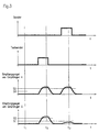
- FIGS. 4-6 show the light outputs and the polarization directions shown along the beam paths of the transmit 8 and receive light beams 10. There are any loss of attenuation when passing through the neglected optical elements.
- FIG. 4 shows the optoelectronic device 1 with a free beam path.
- the transmitted light beams 8 emitted by the transmitter 3 are unpolarized, which is illustrated by the even distribution of the arrows.
- the ones from Transmitter 3 emitted transmission power is used as a reference point for the further Beam path taken and set at 100%.
- the transmitted light beams 8 impinge on the linearly polarizing element 16 Reflector unit 9, the direction of polarization of which is illustrated by a vertical arrow is.
- the transmitted light beams 8 then hit the reflector 17 and are there reflected, some of which are depolarized. In the case of FIG case illustrated, a 35% share is depolarized while a share of 15% maintains the direction of polarization.
- the polarizing element 16 On the second pass the polarizing element 16 is not weakened because of this Direction of polarization with the direction of polarization of the polarizing element 16 matches.
- the depolarized portion on the other hand, increases from 35% 17% weakened. Thus comes from the originally emitted transmission power a proportion of 32% linearly polarized light on the partially transparent mirror 13, the transmitted light beams 8 each being reflected in half and the Penetrate mirror 13.
- the portion of the received light rays 10 penetrating the mirror 13 strikes on the polarizing element of the first receiver 4, its direction of polarization coincides with that of the transmitted light beams 8, so that this without further weakening by the first polarizing element 14 on the first receiver 4 arrive.
- This share is 16% of the original Transmission power.
- the direction of polarization of the polarizing element 15 before the second Receiver 5 is at 90 ° with respect to the incident light beams 10 rotated so that no reception light hits the second receiver 5.
- a highly reflective object 2 is in the Beam path arranged in front of the reflector unit 9, not shown.
- the Object 2 is formed by a reflector 17 on which the transmitter 3 emitted transmission light beams 8 are reflected with almost no loss.
- the Depolarized transmission light beams 8 emitted by the transmitter 3 also remain depolarized after reflection at the reflector 17.
- the received light beams 10 reflected on the reflector 17 strike the semitransparent mirror 13, from where in each case the same proportions of the received light are guided in the direction of the two receivers 4, 5. Because the reception light is depolarized, it will pass through the polarizing Elements 14, 15 each weakened by approximately 50%. Therefore, meet the recipient 4, 5 each about 25% of the original transmission power.
- a diffusely reflecting object 2 is in the Beam path arranged in front of the reflector unit 9, not shown.
- the diffuse Reflection only a small percentage, typically below 1% of the original emitted transmission light power, detected by the receiving optics 12.
- the quantities of light incident on the receivers 4, 5 are correspondingly small. Otherwise the beam path corresponds, in particular also with regard to the Polarization ratios, the case shown in Figure 5.
- the Evaluation unit 6 formed the quotient of the received signals.
- means for Testing provided. By operating these means take with faultless Operation of the device 1 the received signals of the receivers 4, 5 predetermined Switching states with regard to the threshold values S1 and S2 or with respect to the Threshold S, which is checked in the evaluation unit 6.
- This testing can be carried out cyclically, the testing being carried out by the evaluation unit 6 within predetermined time intervals which are in the range of msec, is periodically activated. Such a cyclical test is then carried out if the safety requirements for the device 1 are particularly high.
- the safety requirements for the device 1 are less high, then it can testing within larger time intervals, typically in the range of hours.
- the test is preferably carried out by a External switching device connected to device 1 triggered.
- the Testing can expediently take place when the device 1 and / or the machine to which the device 1 is used for monitoring purposes connected, under maintenance or out of order.
- test end light beam 18 emitting test transmitter 19 is provided for testing.
- the test end light beams 18 run entirely inside the housing 7 and are on the beam-splitting, partially transparent mirror 13 on the Receiver 4, 5 out.
- the test end light beams 18 hit the Back of the partially transparent mirror 13. From there, a share of about 50% of the test transmission light beams 18 are reflected to the first receiver 4. The other part of the test end light rays 18 passes through the partially transparent Mirror 13 and strikes the second receiver 5.
- Transmitter 3 preferably remains switched off during testing. Alternatively, the transmitter 3 could also remain switched on since it only amplifies the effect of the test transmitter 19 and does not interfere.
- the test is divided into two test measurements. During the first test measurement (t 1 ), not only the transmitter 3 but also the test transmitter 19 is switched off. Since then no light is emitted by the device 1, the reception signals of the receivers 4, 5 must each be below the threshold value S1 in the case of error-free operation. Ideally, the levels of the received signals assume the value zero.
- the received signal levels are above the zero level. This is based predominantly on the noise of the receivers 4, 5.
- the transmitter 3 may not be switched off, either this signal combination the operation of the device 1 with a free beam path equivalent. If both received signals are above the threshold values S1 and S2, the transmitter 3 or the test transmitter 19 cannot be switched off and / or both receivers 4, 5 are defective.
- test transmitter 19 is switched off and test transmitter 19 is switched on.
- the test transmitter 19 emits unpolarized test transmission light beams 18, which are guided in equal proportions via the beam-splitting mirror 13 to the receivers 4, 5. Since it is depolarized light, the test end light beams 18 are equally weakened when they pass through the polarizing elements 14, 15.
- the transmission power is selected so that in the error-free case the received signals of both receivers 4, 5 are above the threshold value S2.
- reception signal of a receiver 4, 5 is below this threshold value S2, this receiver 4 or 5 is defective.
- the device 1 switches back to the working mode. There the transmitter 3 is switched on and the test transmitter 19 is switched off. This case is shown under t 3 in FIG. 3 with a free beam path.
- polarizing Element 15 is provided, the polarizing effect is variable.
- this polarizing element 15 consists of a liquid crystal element.
- the liquid crystal element can be switched between two states by applying different voltages. In the first state, the liquid crystal element has a linear polarizing effect. This state is assumed during the work phase in which the transmitter 3 is activated. This case corresponds, for example, to the state of the device 1 at t 3 in FIG. 3.
- the liquid crystal element changes to the second state. In this state, the liquid crystal element has no polarizing one Effect more.
- the Testing is again carried out in two separate test measurements.
- the first Test measurement is carried out analogously to the first exemplary embodiment with the switch off Transmitter 3. Accordingly, the reception signals of the receivers 4, 5 are below S1 in the fault-free state.
- the transmitter 3 is activated during the second test measurement.
- the test measurement expediently takes place with a free beam path.
- the intensity ratios and directions of polarization of the transmitted 8 and received light beams 10 correspond essentially the case shown in Figure 4. Just be the received light beams 10 as they pass through the liquid crystal element formed polarizing element 15 no longer weakened. Corresponding gets the same amount of light on this receiver 5 as on the other receiver 4.
- the reception signals of the two receivers are thus located 4, 5 in the fault-free case above the threshold value S2.
- the test measurements are like follows.
- the first test measurement (t1) the Operation of the reception signals of the receivers 4, 5 each below the Threshold S1 are.
- the second test measurement (t2) the quotient becomes of the received signals evaluated with the threshold value S.
- the quotient of the Received signals from the receivers 4, 5 then lie when the test transmitter is switched on 19 below the threshold S.
Abstract
Description
Die Erfindung betrifft eine optoelektronische Vorrichtung gemäß dem Oberbegriff
des Anspruchs 1.The invention relates to an optoelectronic device according to the preamble
of
Eine derartige als Reflexionslichtschranke ausgebildete Vorrichtung ist aus der EP-A-0 310 932 bekannt. Diese Reflexionslichtschranke weist einen Sendelichtstrahlen emittierenden Sender auf, welchem ein Polarisator vorgeordnet ist. Weiterhin sind zwei Empfänger vorgesehen, welchen jeweils ein eine Polarisationsebene durchlassender Analysator vorgeordnet ist. Schließlich ist in Abstand zum Sender ein Reflektor vorgesehen.Such a device designed as a reflection light barrier is from the EP-A-0 310 932 known. This reflection light barrier has a transmitted light beam emitting transmitter, which is preceded by a polarizer. Furthermore, two receivers are provided, each of which has a polarization plane transmitting analyzer is arranged. Finally is at a distance a reflector is provided for the transmitter.
Die vom Sender emittierten Sendelichtstrahlen sind durch den nachgeordneten Polarisator polarisiert. Dabei wird die Polarisationsebene der Sendelichtstrahlen bei der Reflexion am Reflektor gedreht. Die Polarisationsebene der reflektierten Sendelichtstrahlen bildet die Winkelhalbierende des zwischen den beiden Polarisationsebenen der beiden Analysatoren eingeschlossenen Winkels, der vorzugsweise 90° beträgt.The transmitted light beams emitted by the transmitter are subordinate to the Polarizer polarizes. The polarization plane of the transmitted light rays rotated when reflecting on the reflector. The plane of polarization of the reflected Transmitted light beams form the bisector of the angle between the two Polarization planes of the two included angles, which is preferably 90 °.
An den Ausgang jedes Empfängers ist eine Schwellwertschalter angeschlossen. Diese sind an einen Komparator angeschlossen, der die Ausgangssignale der Schwellwertschalter vergleicht. Im Komparator wird nur ein Ausgangssignal generiert, wenn der Unterschied der Ausgangssignale einen vorgegebenen Wert unterschreitet.A threshold switch is connected to the output of each receiver. These are connected to a comparator, which the output signals of Threshold switch compares. Only one output signal is in the comparator generated when the difference in output signals a predetermined value below.
Eine weitere Vorrichtung dieser Art ist aus der DE 42 38 116 bekannt. Bei dieser Vorrichtung handelt es sich um eine Reflexionslichtschranke mit zwei Empfängern, denen als polarisierendes Mittel ein strahlteilender, teildurchlässiger Spiegel vorgeordnet ist. Die Polarisationsrichtungen der den teildurchlässigen Spiegel durchsetzenden und auf den ersten Empfänger auftreffenden Empfangslichtstrahlen und der am teildurchlässigen Spiegel reflektierten und auf den zweiten Empfänger auftreffenden Empfangslichtstrahlen sind um 90° gegeneinander gedreht. Zum Nachweis der Objekte im Überwachungsbereich wird die Differenz der an den Ausgängen der Empfänger anstehenden Empfangssignale gebildet. Diese Signaldifferenz wird mittels eines Schwellwerts bewertet.Another device of this type is known from DE 42 38 116. At this The device is a reflection light barrier with two Receivers, to whom a beam-splitting, partially transmissive as a polarizing agent Mirror is arranged. The directions of polarization of the semi-transparent Passing through and hitting the first receiver Receiving light rays and those reflected on the partially transparent mirror Receiving light beams incident on the second receiver are at 90 ° rotated against each other. For the detection of objects in the surveillance area becomes the difference between the received signals at the outputs of the receivers educated. This signal difference is determined by means of a threshold rated.
Der Erfindung liegt die Aufgabe zugrunde, eine Vorrichtung der eingangs genannten Art so auszubilden, dass diese im Bereich des Personenschutzes einsetzbar ist.The invention has for its object a device of the aforementioned Type in such a way that it can be used in the area of personal protection is.
Zur Lösung dieser Aufgabe sind die Merkmale der Ansprüche 1 oder 2 vorgesehen.
Vorteilhafte Ausführungsformen und zweckmäßige Weiterbildungen der Erfindung
sind in den Unteransprüchen 3-19 beschrieben.The features of
Gemäß einer ersten Alternative der Erfindung werden die an den Ausgängen der Empfänger anstehenden Empfangssignale jeweils mit zwei unterschiedlichen Schwellwerten S1 und S2 bewertet, wobei Schwellwert S2 oberhalb von S1 liegt. Der Abstand der Schwellwerte ist so gewählt, dass nur bei freiem Strahlengang das Empfangssignal eines Empfängers oberhalb von S2 und das Empfangssignal des anderen Empfängers unterhalb von S1 liegt. Alternativ können die Ausgangssignale der Empfänger auch jeweils mit einem Schwellwert bewertet werden. In diesem Fall werden die dem Schwellwert zugeführten Empfangssignale mittels Verstärkern unterschiedlich verstärkt, wobei die Differenz der Verstärkungsfaktoren der Differenz der Schwellwerte S1 und S2 entspricht. Prinzipiell wäre es auch denkbar, daß die Empfangssignale der Empfänger bei gleicher Verstärkung jeweils mit demselben Schwellwert bewertet werden. In diesem Fall wäre jedoch keine sichere und eindeutige Unterscheidung der Signale bei freiem Strahlengang und bei einem im Strahlengang befindlichen Objekt möglich.According to a first alternative of the invention, the at the outputs the receiver pending reception signals each with two different Threshold values S1 and S2 are evaluated, with threshold value S2 above S1 lies. The distance between the threshold values is selected so that only when there is no Beam path the received signal of a receiver above S2 and that Receive signal of the other receiver is below S1. alternative the output signals of the receivers can also each have a threshold value be rated. In this case, the threshold values are added Received signals amplified differently by means of amplifiers, the difference the amplification factors of the difference between the threshold values S1 and S2 equivalent. In principle, it would also be conceivable that the received signals of the Recipients with the same gain are rated with the same threshold become. In this case, however, there would be no sure and clear distinction the signals with free beam path and with one in the beam path located object possible.
Dabei liegt das Empfangssignal desjenigen Empfängers oberhalb von S2, dessen polarisierendes Element dieselbe oder nahezu dieselbe Polarisationsrichtung aufweist wie das polarisierende Element der Reflektoreinheit. Das polarisierende Element des anderen Empfängers ist gegenüber der Polarisationsrichtung des polarisierenden Elements der Reflektoreinheit um einen Winkel α, der im Bereich 45° < α < 135° liegt und vorzugsweise 90° beträgt, gedreht. Demzufolge trifft auf diesen Empfänger bei freiem Strahlengang nur eine geringe Lichtmenge.The received signal of the receiver is above S2, whose polarizing element the same or almost the same polarization direction has like the polarizing element of the reflector unit. The polarizing The element of the other receiver is opposite to the direction of polarization of the polarizing element of the reflector unit by an angle α which lies in the range 45 ° <α <135 ° and is preferably 90 °. As a result, strikes this receiver with only a small beam path Amount of light.
Mit dieser Vorrichtung können Objekte aller Art, die das auftreffende Sendelicht depolarisieren, sicher erkannt werden. Durch die depolarisierende Wirkung des Objekts treffen auf die Empfänger vergleichbare Lichtmengen.With this device, objects of all kinds can be emitted by the incident light depolarize, be recognized safely. Due to the depolarizing effect of the object hit comparable amounts of light on the receiver.
Reflektiert das Objekt das Licht diffus und nur sehr schwach, so liegen die Empfangssignale beider Empfänger unterhalb des Schwellwerts S1.If the object reflects the light diffusely and only very weakly, then they are lying Receive signals of both receivers below the threshold S1.
Befindet sich ein stark reflektierendes Objekt im Strahlengang, so gelangt eine große Lichtmenge auf die Empfänger, so daß deren Empfangssignale jeweils oberhalb von S2 liegen.If there is a highly reflective object in the beam path, one will pass large amount of light on the receiver, so that their received signals each lie above S2.
In jedem Fall weichen diese Schaltzustände am Ausgang der Empfänger von den Schaltzuständen bei freiem Strahlengang ab, so daß eine sichere Detektion der Objekte gewährleistet ist.In any case, these switching states at the output of the receiver differ the switching states with free beam path, so that a reliable detection the objects is guaranteed.
Gemäß einer weiteren Alternative der Erfindung wird der Quotient der an den Ausgängen der Empfänger anstehenden Signale gebildet. Durch die Quotientenbildung werden systematische Meßfehler, die durch unterschiedliche Ausdehnungen des Überwachungsbereichs entstehen, eliminiert. Dies bevorzugt eine Quotientenbildung der Empfangssignale gegenüber einer Differenzbildung, die ebenfalls prinzipiell denkbar wäre. Der Quotient der Empfangssignale wird mit einem Schwellwert S bewertet. Dieser Schwellwert S ist so gewählt, daß sich bei freiem Strahlengang der Vorrichtung ein anderer Schaltzustand ergibt als bei einem im Strahlengang befindlichen Objekt, und zwar unabhängig von dessen Reflexionseigenschaften. Zusätzlich werden die Empfangssignale der Empfänger einzeln mit dem Schwellwert S1 bewertet.According to a further alternative of the invention, the quotient of the to Outputs of the receiver pending signals formed. By forming the quotient are systematic measurement errors caused by different dimensions of the surveillance area are eliminated. This is preferred a quotient formation of the received signals compared to a difference formation, which would also be conceivable in principle. The quotient of the received signals is evaluated with a threshold value S. This threshold value S is selected that there is a different switching state when the beam path of the device is clear results as for an object in the beam path, and that independently of its reflective properties. In addition, the received signals the receiver is individually assessed with the threshold value S1.
Die erfindungsgemäße Vorrichtung weist zudem Mittel zur Testung auf. Damit kann die Funktionsfähigkeit des Senders und der Empfänger zyklisch oder in vorgegebenen Intervallen überprüft werden. Die Überprüfung erfolgt derart, daß im fehlerfreien Betrieb bei Betätigen der Mittel zur Testung die Empfangssignale der Empfänger vorgegebene Schaltzustände bezüglich der Schwellwerte S1 und S2 bzw. des Schwellwerts S einnehmen müssen.The device according to the invention also has means for testing. In order to can change the functionality of the transmitter and the receiver cyclically or in predetermined intervals are checked. The check is done in such a way that in error-free operation when operating the means for testing the received signals the receiver predetermined switching states with respect to Threshold values S1 and S2 or the threshold value S must be taken.
Durch diese Überprüfung können interne Gerätestörungen sofort erkannt und angezeigt werden. Bei Anwendungen im Bereich des Personenschutzes wird die Vorrichtung üblicherweise zur Überwachung einer Maschine oder dergleichen eingesetzt. Tritt ein interner Gerätefehler in der Vorrichtung auf, so wird aus Sicherheitsgründen die Maschine abgeschaltet.Through this check, internal device malfunctions can be immediately recognized and are displayed. For applications in the field of personal protection the device usually for monitoring a machine or the like used. If an internal device error occurs in the device, then the machine is switched off for safety reasons.
Die Erfindung wird im nachstehenden anhand der Zeichnungen erläutert. Es zeigen:
- Figur 1:
- Schematische Darstellung eines Ausführungsbeispiels der erfindungsgemäßen Vorrichtung bei eingeschaltetem Sender,
- Figur 2:
- Vorrichtung gemäß
Figur 1 bei ausgeschaltetem Sender und eingeschaltetem Testsender, - Figur 3:
- Impulsdiagramm für den Betrieb des Senders, des Testsenders und der Empfänger,
- Figur 4:
- Schematische Darstellung der Intensitätsverläufe der Sende- und Empfangslichtstrahlen bei freiem Strahlengang,
- Figur 5:
- Schematische Darstellung der Intensitätsverläufe der Sende- und Empfangslichtstrahlen bei einem im Strahlengang angeordneten spiegelnden Objekt,
- Figur 6:
- Schematische Darstellung der Intensitätsverläufe der Sende- und Empfangslichtstrahlen bei einem im Strahlengang angeordneten diffus reflektierenden Objekt.
- Figure 1:
- Schematic representation of an embodiment of the device according to the invention when the transmitter is switched on,
- Figure 2:
- 1 with the transmitter switched off and the test transmitter switched on,
- Figure 3:
- Pulse diagram for the operation of the transmitter, the test transmitter and the receiver,
- Figure 4:
- Schematic representation of the intensity profiles of the transmitted and received light beams with a free beam path,
- Figure 5:
- Schematic representation of the intensity profiles of the transmitted and received light beams in a reflecting object arranged in the beam path,
- Figure 6:
- Schematic representation of the intensity profiles of the transmitted and received light beams in a diffusely reflecting object arranged in the beam path.
Die Figuren 1 und 2 zeigen ein erstes Ausführungsbeispiel einer optoelektronischen
Vorrichtung 1 zum Erfassen von Objekten 2 in einem Überwachungsbereich.
An einem Ende des Überwachungsbereichs sind ein Sender 3 und zwei
Empfänger 4, 5 angeordnet, die an eine gemeinsame Auswerteeinheit 6 angeschlossen
und in einem Gehäuse 7 integriert sind. Der Sender 3 ist vorzugsweise
von einer Leuchtdiode gebildet und wird im Pulsbetrieb betrieben. Alternativ
kann der Sender 3 von einem Laser gebildet sein. Die Empfänger 4, 5 sind
von vorzugsweise baugleichen Photodioden gebildet. Die Auswerteeinheit 6
besteht aus einem Microcontroller oder ist in einem ASIC integriert.Figures 1 and 2 show a first embodiment of an
Bei freiem Strahlengang werden die vom Sender 3 emittierten Sendelichtstrahlen
8 auf eine am gegenüberliegenden Ende des Überwachungsbereichs angeordnete
Reflektoreinheit 9 geführt. Die von dort reflektierten Empfangslichtstrahlen
10 sind auf die Empfänger 4, 5 geführt.If the beam path is clear, the transmitted light beams emitted by the
In der Frontwand des Gehäuses 7 ist eine Sendeoptik 11 angebracht, durch
welche die Sendelichtstrahlen 8 geführt sind. Zudem ist in der Gehäusewand
eine Empfangsoptik 12 vorgesehen, die von den Empfangslichtstrahlen 10
durchsetzt wird. Die Sende- 11 und Empfangsoptik 12 sind jeweils von einer
Linse gebildet.In the front wall of the
Zwischen der Empfangsoptik 12 und den Empfängern 4, 5 ist ein strahlteilender,
teildurchlässiger Spiegel 13 vorgesehen, dessen Frontfläche und Rückseite
jeweils um 45° gegenüber der Strahlachse der auftreffenden Empfangslichtstrahlen
10 geneigt sind. Die die Empfangsoptik 12 durchsetzenden Empfangslichtstrahlen
10 treffen auf die Frontseite des teildurchlässigen Spiegels 13. Ein
Teil der Empfangslichtstrahlen 10 durchsetzt den teildurchlässigen Spiegel 13
und trifft auf den dahinter angeordneten ersten Empfänger 4. Der restliche Teil
der Empfangslichtstrahlen 10 wird am teildurchlässigen Spiegel 13 reflektiert
und trifft auf den zweiten Empfänger 5.Between the receiving
Jedem Empfänger 4, 5 ist ein linear polarisierendes Element 14, 15 vorgeordnet,
welches vorzugsweise als Polarisationsfilter ausgebildet ist.A linearly
In einer weiteren nicht dargestellten Ausführungsform der Erfindung ist dem
teildurchlässigen Spiegel 13 ein Umlenkelement vorgeordnet. An diesem Umlenkelement
werden die Sendelichtstrahlen 8 so umgelenkt, daß diese koaxial
zu den Empfangslichtstrahlen 10 im Überwachungsbereich geführt werden.
Zweckmäßigerweise besteht das Umlenkelement aus einem weiteren teildurchlässigen
Spiegel 13, dessen Spiegelfläche parallel zur Spiegelfläche des ersten
teildurchlässigen Spiegels 13 verläuft. Der Sender 3 ist unterhalb des zweiten
teildurchlässigen Spiegels 13 angeordnet. In diesem Fall wird nur noch eine
Linse benötigt, die gleichzeitig die Sende- 3 und Empfangslichtstrahlen 10 fokussiert.In a further embodiment of the invention, not shown, the
Partially
Die Reflektoreinheit 9 weist ebenfalls ein weiteres linear polarisierendes Element
16 auf, welches unmittelbar vor einem Reflektor 17 angeordnet ist, der als
Trippelreflektor oder als Reflexfolie ausgebildet sein kann. Prinzipiell kann
anstelle eines Reflektor 17 auch ein Spiegel verwendet werden. The
Die Polarisationsrichtung der polarisierenden Elemente 14, 16 in der Reflektoreinheit
9 und am ersten Empfänger 4 stimmen im wesentlichen, vorzugsweise
mit einer Winkeldifferenz kleiner als 10°, überein. Im vorliegenden Ausführungsbeispiel
stimmen die Polarisationsrichtungen exakt überein. Die Polarisationsrichtung
des polarisierenden Elements 15 am zweiten Empfänger 5 ist
hierzu um einen Winkel α gedreht, der im Bereich 45° < α < 135° liegt. Im
vorliegenden Ausführungsbeispiel beträgt der Winkel α = 90°.The direction of polarization of the
Ist der Sender 3 von einem Laser gebildet, so sind die Sendelichtstrahlen 8 linear
polarisiert. Dabei ist deren Polarisationsrichtung um 45° gegenüber der
Polarisationsrichtung des polarisierenden Elements 16 gedreht.If the
Die an den Ausgängen der Empfänger 4, 5 anstehenden Empfangssignale werden
jeweils mit zwei Schwellwerten S1 und S2 bewertet, wobei der Schwellwert
S2 oberhalb von S1 liegt. Die Lage der Empfangssignale der Empfänger 4,
5 relativ zu den Schwellwerten S1 und S2 definiert den Schaltzustand der Vorrichtung
1.The received signals pending at the outputs of the
Die Schwellwerte sind in Abhängigkeit der Polarisationsrichtungen der polarisierenden
Elemente 14, 15 gewählt.The threshold values are dependent on the polarization directions of the
Insbesondere ist der Abstand zwischen den Schwellwerten S1 und S2 so gewählt,
daß nur bei freiem Strahlengang das Empfangssignale des ersten Empfänger
4 oberhalb von S2 liegt und gleichzeitig das Empfangssignal des zweiten
Empfängers 5 unterhalb von S1 liegt. Dies wird dadurch erreicht, daß der
Schwellwert S2 etwa 10% unterhalb des Empfangspegels des ersten Empfängers
4 bei freiem Strahlengang liegt und der Schwellwert S1 etwa 80% unterhalb
dieses Empfangspegels liegt.In particular, the distance between the threshold values S1 and S2 is chosen so
that the received signals of the first receiver only when the beam path is clear
4 lies above S2 and at the same time the reception signal of the
In den Figuren 4 - 6 sind die Lichtleistungen und die Polarisationsrichtungen entlang der Strahlengänge der Sende- 8 und Empfangslichtstrahlen 10 dargestellt. Dabei sind eventuelle Dämpfungsverluste beim Durchgang durch die optischen Elemente vernachlässigt. FIGS. 4-6 show the light outputs and the polarization directions shown along the beam paths of the transmit 8 and receive light beams 10. There are any loss of attenuation when passing through the neglected optical elements.
In Figur 4 ist die optoelektronische Vorrichtung 1 bei freiem Strahlengang dargestellt.
Die vom Sender 3 emittierten Sendelichtstrahlen 8 sind unpolarisiert,
was durch die gleichmäßige Verteilung der Pfeile veranschaulicht ist. Die vom
Sender 3 emittierte Sendeleistung wird als Bezugspunkt für den weiteren
Strahlverlauf genommen und mit 100% angesetzt.FIG. 4 shows the
Die Sendelichtstrahlen 8 treffen auf das linear polarisierende Element 16 der
Reflektoreinheit 9, dessen Polarisationsrichtung mit einem vertikalen Pfeil veranschaulicht
ist.The transmitted
Nur der in dieser Polarisationsrichtung polarisierte Teil des Sendelichts durchdringt
das polarisierende Element 16. Dieser Teil beträgt etwa 50% der ursprünglichen
Sendeleistung.Only the part of the transmitted light polarized in this polarization direction penetrates
the
Die Sendelichtstrahlen 8 treffen dann auf den Reflektor 17 und werden dort
reflektiert, wobei diese dabei zum Teil depolarisiert werden. Bei dem in Figur 4
dargestellten Fall wird ein Anteil von 35% depolarisiert, während ein Anteil
von 15% die Polarisationsrichtung beibehält. Beim zweiten Durchtritt durch
das polarisierende Element 16 wird dieser Anteil nicht geschwächt, da dessen
Polarisationsrichtung mit der Polarisationsrichtung des polarisierenden Elements
16 übereinstimmt. Der depolarisierte Anteil wird dagegen von 35% auf
17% geschwächt. Somit gelangt von der ursprünglich emittierten Sendeleistung
ein Anteil von 32% linear polarisiertem Licht auf den teildurchlässigen Spiegel
13, wobei die Sendelichtstrahlen 8 je zur Hälfte reflektiert werden und den
Spiegel 13 durchdringen.The transmitted
Der den Spiegel 13 durchdringende Anteil der Empfangslichtstrahlen 10 trifft
auf das polarisierende Element des ersten Empfängers 4, dessen Polarisationsrichtung
mit derjenigen der Sendelichtstrahlen 8 übereinstimmt, so daß diese
ohne weitere Schwächung durch das erste polarisierende Element 14 auf den
ersten Empfänger 4 gelangen. Dieser Anteil beträgt 16% der ursprünglichen
Sendeleistung. The portion of the received
Die Polarisationsrichtung des polarisierenden Elements 15 vor dem zweiten
Empfänger 5 ist um 90° bezüglich der auftreffenden Empfangslichtstrahlen 10
gedreht, so daß kein Empfangslicht auf den zweiten Empfänger 5 trifft.The direction of polarization of the
Entsprechend der auf die Empfänger 4, 5 auftreffenden Lichtmengen liegt das
Empfangssignal am Ausgang des ersten Empfängers 4 oberhalb des Schwellwerts
S2 und das Empfangssignal am Ausgang des zweiten Empfängers 5 unterhalb
des Schwellwerts S1.This is according to the amount of light incident on the
Bei dem in Figur 5 dargestellten Fall ist ein hochreflektierendes Objekt 2 im
Strahlengang vor der nicht dargestellten Reflektoreinheit 9 angeordnet. Das
Objekt 2 ist von einem Reflektor 17 gebildet, an welchem die vom Sender 3
emittierten Sendelichtstrahlen 8 nahezu ohne Verlust reflektiert werden. Die
vom Sender 3 emittierten depolarisierten Sendelichtstrahlen 8 bleiben auch
nach der Reflexion am Reflektor 17 depolarisiert.In the case shown in FIG. 5, a highly
Die am Reflektor 17 reflektierten Empfangslichtstrahlen 10 treffen auf den
teildurchlässigen Spiegel 13, wobei von dort jeweils gleiche Anteile des Empfangslichts
in Richtung der beiden Empfänger 4, 5 geführt sind. Da das Empfangslicht
depolarisiert ist, wird es beim Durchtritt durch die polarisierenden
Elemente 14, 15 jeweils um etwa 50% geschwächt. Daher treffen auf die Empfänger
4, 5 jeweils etwa 25% der ursprünglichen Sendeleistung.The received
Dies führt zu Empfangssignalen an den Empfängern 4, 5, welche jeweils oberhalb
der Schwellwerte S2 liegen. Diese Empfangssignale unterscheiden sich
eindeutig von den Schaltzuständen bei freiem Strahlengang, so daß eine sichere
Detektion des Objekte 2 gewährleistet ist.This leads to reception signals at the
Bei dem in Figur 6 dargestellten Fall ist ein diffus reflektierendes Objekt 2 im
Strahlengang vor der nicht dargestellten Reflektoreinheit 9 angeordnet. Von
dem auf das Objekt 2 auftreffenden Sendelicht wird bedingt durch die diffuse
Reflexion nur ein kleiner Anteil, typischerweise unterhalb von 1% der ursprünglich
emittierten Sendelichtleistung, von der Empfangsoptik 12 erfaßt.
Entsprechend gering sind die auf die Empfänger 4, 5 auftreffenden Lichtmengen.
Ansonsten entspricht der Strahlengang, insbesondere auch hinsichtlich der
Polarisationsverhältnisse, dem in Figur 5 dargestellten Fall.In the case shown in FIG. 6, a diffusely reflecting
Da auf die Empfänger 4, 5 jeweils nur ein Anteil von weniger als 0,25% der
ursprünglich emittierten Sendelichtleistung trifft, liegen die Empfangssignale
jeweils unterhalb des Schwellwerts S1. Auch diese Schaltzustände unterscheiden
sich eindeutig von den Schaltzuständen bei freiem Strahlengang, so daß
auch in diesem Fall eine sichere Objekterkennung gewährleistet ist.Since only a share of less than 0.25% of each of the
Gemäß einer weiteren nicht dargestellten Alternative der Erfindung wird in der
Auswerteeinheit 6 der Quotient der Empfangssignale gebildet. Im vorliegenden
Fall wird der Wert des am Empfänger 4 anstehenden Empfangssignales durch
den Wert des am Empfänger 5 anstehenden Empfangssignals dividiert. Bei
freiem Strahlengang ergibt sich für den Quotienten ein Zahlenwert mit x >> 1.
Ist ein Objekt 2 mit beliebigem Reflexionsgrad im Strahlengang angeordnet, so
ergibt sich für den Quotienten ein Zahlenwert im Bereich x = 1 . Um eine sichere
Detektion der Objekte 2 zu gewährleisten, liegt die Höhe des Schwellwerts
etwa im Bereich 2 < S ≤ 10. Demzufolge ist gewährleistet, daß der
Schwellwert S nur bei freiem Strahlengang überschritten wird. Zusätzlich werden
die Empfangssignale der Empfänger 4, 5 einzeln mit dem Schwellwert S1
bewertet.According to a further alternative of the invention, not shown, in the
Zur Überprüfung der Funktionssicherheit der Vorrichtung 1 sind Mittel zur
Testung vorgesehen. Durch Betätigen dieser Mittel nehmen bei fehlerfreiem
Betrieb der Vorrichtung 1 die Empfangssignale der Empfänger 4, 5 vorgegebenen
Schaltzustände bezüglich der Schwellwerte S1 und S2 bzw. bezüglich des
Schwellwerts S an, was in der Auswerteeinheit 6 abgeprüft wird.To check the functional reliability of the
Diese Testung kann zyklisch erfolgen, wobei die Testung von der Auswerteeinheit
6 innerhalb vorgegebener Zeitintervalle, die im Bereich von msec liegen,
periodisch aktiviert wird. Eine derartige zyklische Testung erfolgt dann,
wenn die Sicherheitsanforderungen an die Vorrichtung 1 besonders hoch sind.This testing can be carried out cyclically, the testing being carried out by the
Sind die Sicherheitsanforderungen an die Vorrichtung 1 weniger hoch, so kann
die Testung innerhalb größerer Zeitintervalle, die typischerweise im Bereich
von Stunden liegen, erfolgen. Dabei wird die Testung vorzugsweise durch ein
externes an die Vorrichtung 1 angeschlossenes Schaltgerät ausgelöst. Die
Testung kann zweckmäßigerweise dann erfolgen, wenn die Vorrichtung 1 und /oder
die Maschine, an welche die Vorrichtung 1 zu Überwachungszwecken
angeschlossen ist, gewartet wird oder außer Betrieb ist.If the safety requirements for the
Bei dem in den Figuren 1 und 2 dargestellten Ausführungsbeispiel ist als Mittel
zur Testung ein Testsendelichtstrahlen 18 emittierender Testsender 19 vorgesehen.
Die Testsendelichtstrahlen 18 verlaufen vollständig im Inneren des Gehäuses
7 und sind über den strahlteilenden, teildurchlässigen Spiegel 13 auf die
Empfänger 4, 5 geführt. Dabei treffen die Testsendelichtstrahlen 18 auf die
Rückseite des teildurchlässigen Spiegels 13. Von dort wird ein Anteil von etwa
50% der Testsendelichtstrahlen 18 zum ersten Empfänger 4 reflektiert. Der
andere Teil der Testsendelichtstrahlen 18 durchsetzt den teildurchlässigen
Spiegel 13 und trifft auf den zweiten Empfänger 5.In the embodiment shown in Figures 1 and 2 is as a means
a test
Die Durchführung der Testung ist in Figur 3 veranschaulicht. Während der
Testung bleibt der Sender 3 vorzugsweises ausgeschaltet. Alternativ könnte der
Sender 3 auch eingeschaltet bleiben, da er die Wirkung des Testsenders 19 nur
verstärkt und nicht stört. Die Testung untergliedert sich in zwei Testmessungen.
Bei der ersten Testmessung (t1) wird nicht nur der Sender 3, sondern auch
der Testsender 19 abgeschaltet. Da dann von der Vorrichtung 1 keinerlei
Licht emittiert wird, müssen bei fehlerfreiem Betrieb die Empfangssignale der
Empfänger 4, 5 jeweils unterhalb des Schwellwerts S1 liegen. Im Idealfall
nehmen die Pegel der Empfangssignale den Wert Null an.The implementation of the test is illustrated in FIG. 3.
Im Realfall liegen die Empfangssignalpegel oberhalb des Nullpegels. Dies beruht
vorwiegend auf dem Rauschen der Empfänger 4, 5. In the real case, the received signal levels are above the zero level. This is based
predominantly on the noise of the
Liegt im Fehlerfall eines der Empfangssignale oberhalb des Schwellwerts S1,
so ist der entsprechende Empfänger 4 oder 5 defekt. Handelt es sich um den
ersten Empfänger 4, so ist eventuell auch der Sender 3 nicht ausschaltbar, da
diese Signalkombination dem Betrieb der Vorrichtung 1 bei freiem Strahlengang
entspricht. Liegen beide Empfangssignale oberhalb der Schwellwerte S1
und S2, so läßt sich der Sender 3 oder der Testsender 19 nicht ausschalten und /oder
beide Empfänger 4, 5 sind defekt.If one of the received signals is above the threshold S1 in the event of an error,
the corresponding
Während der zweiten Testmessung (t2) ist der Sender 3 ausgeschaltet und der
Testsender 19 eingeschaltet. Der Testsender 19 emittiert dabei unpolarisierte
Testsendelichtstrahlen 18, die zu gleichen Anteilen über den strahlteilenden
Spiegel 13 auf die Empfänger 4, 5 geführt sind. Da es sich um depolarisiertes
Licht handelt werden die Testsendelichtstrahlen 18 bei Durchgang durch die
polarisierenden Elemente 14, 15 gleichermaßen geschwächt. Die Sendeleistung
ist so gewählt, daß im fehlerfreien Fall die Empfangssignale beider Empfänger
4, 5 oberhalb des Schwellwerts S2 liegen.During the second test measurement (t 2 ),
Liegt das Empfangssignal eines Empfängers 4, 5 unterhalb dieses Schwellwerts
S2, so ist dieser Empfänger 4 oder 5 defekt.If the reception signal of a
Durch Verknüpfung der Ergebnisse beider Testmessungen läßt sich somit feststellen,
ob der Sender 3 bzw. der Testsender 19 oder einer der Empfänger 4, 5
defekt ist.By linking the results of both test measurements, it can be determined
whether the
Nach Abschluß der Testmessungen wechselt die Vorrichtung 1 wieder in den
Arbeitsbetrieb. Dort ist der Sender 3 eingeschaltet und der Testsender 19 ausgeschaltet.
Unter t3 in Figur 3 ist dieser Fall bei freiem Strahlengang dargestellt.After the test measurements have been completed, the
In einem weiteren nicht dargestellten Ausführungsbeispiel ist als Mittel zur
Testung anstelle des Testsenders 19 vor dem Empfänger 4, 5 ein polarisierendes
Element 15 vorgesehen, dessen polarisierende Wirkung veränderbar ist. In a further embodiment, not shown, is used as a means for
Testing instead of the
Im vorliegenden Ausführungsbeispiel besteht dieses polarisierende Element 15
aus einem Flüssigkristallelement. Durch Anlegen unterschiedlicher Spannungen
kann das Flüssigkristallelement zwischen zwei Zuständen umgeschaltet
werden. Im ersten Zustand wirkt das Flüssigkristallelement linear polarisierend.
Dieser Zustand wird während der Arbeitsphase eingenommen, in welcher der
Sender 3 aktiviert ist. Dieser Fall entspricht beispielsweise dem Zustand der
Vorrichtung 1 bei t3 in Figur 3.In the present exemplary embodiment, this
Während der Testung wechselt das Flüssigkristallelement in den zweiten Zustand. In diesem Zustand hat das Flüssigkristallelement keine polarisierende Wirkung mehr.During the test, the liquid crystal element changes to the second state. In this state, the liquid crystal element has no polarizing one Effect more.
Die Testung erfolgt wiederum in zwei getrennten Testmessungen. Die erste
Testmessung erfolgt analog zum ersten Ausführungsbeispiel bei abgeschaltetem
Sender 3. Entsprechend müssen die Empfangssignale der Empfänger 4, 5
im fehlerfreien Zustand unterhalb von S1 liegen.Testing is again carried out in two separate test measurements. The first
Test measurement is carried out analogously to the first exemplary embodiment with the switch off
Während der zweiten Testmessung ist der Sender 3 aktiviert. Die Testmessung
erfolgt zweckmäßigerweise bei freiem Strahlengang. Die Intensitätsverhältnisse
und Polarisationsrichtungen der Sende- 8 und Empfangslichtstrahlen 10 entsprechen
im wesentlichen dem in Figur 4 dargestellten Fall. Lediglich werden
die Empfangslichtstrahlen 10 beim Durchgang durch das vom Flüssigkristallelement
gebildeten polarisierenden Element 15 nicht mehr geschwächt. Entsprechend
gelangt auf diesen Empfänger 5 dieselbe Lichtmenge wie auf den
anderen Empfänger 4. Somit liegen die Empfangssignale der beiden Empfänger
4, 5 im fehlerfreien Fall oberhalb des Schwellwerts S2.The
Die Auswertung, ob im Fehlerfall der Sender 3 oder einer der Empfänger 4, 5
defekt ist, erfolgt analog zum ersten Ausführungsbeispiel.The evaluation of whether the
Gemäß der zweiten Alternative der Erfindung werden die Testmessungen wie
folgt durchgeführt. Während der ersten Testmessung (t1) müssen bei fehlerfreiem
Betrieb die Empfangssignale der Empfänger 4, 5 jeweils unterhalb des
Schwellwerts S1 liegen. Während der zweiten Testmessung (t2) wird der Quotient
der Empfangssignale mit dem Schwellwert S bewertet. Der Quotient der
Empfangssignale der Empfänger 4, 5 liegt dann bei eingeschaltetem Testsender
19 unterhalb des Schwellwerts S.According to the second alternative of the invention, the test measurements are like
follows. During the first test measurement (t1), the
Operation of the reception signals of the
Claims (19)
- Optoelectronic device (1) for the detection of objects (2) in a monitoring region, at one end of which there are arranged a transmitter (3) transmitting a transmitted light beam (8) and two receivers (4, 5) - which each receive received light beams (10) - each with a respective upstream first and second linearly polarising element (14, 15), the polarisation directions of the elements being rotated relative to one another through an angle α in the range 45° < α < 135°, and at the other end of which there is arranged a reflector unit (9) consisting of a reflector (17) and an upstream third linearly polarising element (16), the polarisation direction of which substantially corresponds with the polarisation direction of the first or second polarising element (14, 15), characterised in that the received signals present at outputs of the receivers (4, 5) are evaluated in each instance by two different threshold values S1 and S2, wherein the threshold value S2 lies above the threshold value S1 and the spacing thereof is so selected that the received signal of one receiver (4) lies above S2 and the received signal of the second receiver (5) lies below S1 only in the case of a free beam path and that means (18) for testing the device (1) are provided by the actuation of which the received signals of the receivers (4, 5) take up predetermined switching states with respect to the threshold values S1 and S2 in the case of fault-free operation.
- Optoelectronic device (1) for the detection of objects (2) in a monitoring region, at one end of which there are arranged a transmitter (3) transmitting a transmitted light beam (8) and two receivers (4, 5) - which each receive received light beams (10) - each with a respective upstream first and second linearly polarising element (14, 15), the polarisation directions of the elements being rotated relative to one another through an angle α in the range 45° < α < 135°, and at the other end of which there is arranged a reflector unit (9) consisting of a reflector (17) and an upstream third linearly polarising element (16), the polarisation direction of which substantially corresponds with the polarisation direction of the first or second polarising element (14, 15), characterised in that the quotient of the received signals present at the outputs of the receivers (4, 5) is formed and this is evaluated by a threshold value S, and that means (19) for testing the device (1) are provided, by the actuation of which the quotient of the received signals relative to the threshold value S adopts a predetermined value in the case of fault-free operation.
- Optoelectronic device according to claim 1 or 2, characterised in that the testing takes place cyclically.
- Optoelectronic device according to one of claims 1 to 3, characterised in that the testing is carried out by external activation of the means (19) for the testing.
- Optoelectronic device according to one of claims 1 to 4, characterised in that the polarisation directions of the first and second polarising element (14, 15) are rotated relative to one another through α = 90°.
- Optoelectronic device according to claim 5, characterised in that the received light beams (10) are guided by way of a beam dividing, partly transparent mirror (13) to the receivers (4, 5).
- Optoelectronic device according to claim 6, characterised in that a deflecting element, at which the transmitted light beams (8) are reflected so that they are guided parallel to the received light beams (10) in the monitoring region, is arranged in front of the partly transparent mirror (13).
- Optoelectronic device according to claim 7, characterised in that the deflecting element is formed by a partly transparent mirror (13).
- Optoelectronic device according to one of claims 1 to 8, characterised in that a test transmitter (19), the test transmitted light beams (18) of which are directed to the receivers (4, 5), is provided for the testing of the optoelectronic device.
- Optoelectronic device according to one of claims 7 to 9, characterised in that the test transmitted light beams (18) transmitted by the test transmitter (19) are guided to the receivers (4, 5) by way of the partly transparent mirror (13).
- Optoelectronic device according to claim 9 or 10, characterised in that the transmitter (3) is switched off during the testing.
- Optoelectronic device according to claim 10 or 11, characterised in that in the case of fault-free operation thereof during a first test measurement with the transmitter (3) and test transmitter (19) switched off the received signals of the receivers (4, 5) each lie below the threshold value S1.
- Optoelectronic device according to one of claims 10 to 12, characterised in that in the case of fault-free operation thereof during a second test measurement with the transmitter (3) switched off and the test transmitter (19) switched on the received signals of the receivers (4, 5) each lie above the threshold value S2 or the quotient of the received signals of the receivers (4, 5) lies below the threshold value S, wherein the received signal of the receiver (4) is divided by the received signal of the receiver (5).
- Optoelectronic device according to one of claims 1 to 8, characterised in that for the testing thereof the polarisation effect of the polarising element (15) in front of the receiver (5) is variable.
- Optoelectronic device according to claim 14, characterised in that the polarising element (15) is formed by a liquid crystal element.
- Optoelectronic device according to claim 14 or 15, characterised in that in the case of the test measurements the polarisation effect of the polarising element (15) is cancelled.
- Optoelectronic device according to claim 16, characterised in that in the case of fault-free operation thereof during a first test measurement with the transmitter (3) switched off the received signals of the receivers (4, 5) lie below the threshold value S1 and during a second test measurement with the receiver (3) switched on and the beam path free lie above S2, or that the quotient of the received signals of the receivers (4, 5) during the second test measurement lies below the threshold value S, wherein the received signal of the receiver (4) is divided by the received signal of the receiver (5).
- Optoelectronic device according to one of claims 1 to 17, characterised in that the transmitter (3) is formed by a luminescent diode.
- Optoelectronic device according to one of claims 1 to 17, characterised in that the transmitter (3) is formed by a laser, wherein the polarisation direction of the transmitted light beams (8) transmitted by the laser is rotated approximately through 45° with respect to the polarisation direction of the linearly polarising element (16) of the reflector unit (9).
Applications Claiming Priority (5)
| Application Number | Priority Date | Filing Date | Title |
|---|---|---|---|
| DE19749199 | 1997-11-07 | ||
| DE19749199 | 1997-11-07 | ||
| DE19810231 | 1998-03-10 | ||
| DE19810231A DE19810231C2 (en) | 1997-11-07 | 1998-03-10 | Optoelectronic device |
| PCT/EP1998/007136 WO1999024850A1 (en) | 1997-11-07 | 1998-11-09 | Optoelectronic device |
Publications (2)
| Publication Number | Publication Date |
|---|---|
| EP0951653A1 EP0951653A1 (en) | 1999-10-27 |
| EP0951653B1 true EP0951653B1 (en) | 2003-01-02 |
Family
ID=26041396
Family Applications (1)
| Application Number | Title | Priority Date | Filing Date |
|---|---|---|---|
| EP98963428A Expired - Lifetime EP0951653B1 (en) | 1997-11-07 | 1998-11-09 | Optoelectronic device |
Country Status (4)
| Country | Link |
|---|---|
| US (1) | US6316762B1 (en) |
| EP (1) | EP0951653B1 (en) |
| AT (1) | ATE230493T1 (en) |
| WO (1) | WO1999024850A1 (en) |
Families Citing this family (7)
| Publication number | Priority date | Publication date | Assignee | Title |
|---|---|---|---|---|
| US6701036B2 (en) * | 2001-03-19 | 2004-03-02 | The Research Foundation Of State University Of New York | Mirror, optical switch, and method for redirecting an optical signal |
| DE102007046769A1 (en) * | 2007-09-29 | 2009-04-16 | Leuze Electronic Gmbh + Co. Kg | sensor arrangement |
| US8471704B2 (en) * | 2010-04-13 | 2013-06-25 | Cedes Ag | Door system comprising a sensor device for monitoring vertical door edges |
| US10148348B2 (en) * | 2015-07-17 | 2018-12-04 | Corning Optical Communications LLC | Optical-electrical interface devices and systems with optical communication pathway redundancy |
| EP3232225A1 (en) * | 2016-04-11 | 2017-10-18 | Leuze electronic GmbH + Co KG | Sensor assembly |
| US9761113B1 (en) * | 2016-07-20 | 2017-09-12 | Banner Engineering Corp. | Light curtain protection system featuring a passive optical module |
| DE102019115792B4 (en) | 2019-06-11 | 2024-05-02 | Sick Ag | Triangulation light sensor |
Family Cites Families (11)
| Publication number | Priority date | Publication date | Assignee | Title |
|---|---|---|---|---|
| US4224608A (en) * | 1978-11-13 | 1980-09-23 | Detection Systems, Inc. | Single terminal detection system |
| US4339660A (en) * | 1980-05-15 | 1982-07-13 | Erwin Sick Gmbh Optik-Elektronik | Reflection light barrier apparatus for recognizing both strongly and weakly reflecting objects |
| US4710760A (en) * | 1985-03-07 | 1987-12-01 | American Telephone And Telegraph Company, At&T Information Systems Inc. | Photoelastic touch-sensitive screen |
| DE3514643A1 (en) | 1985-04-23 | 1986-10-23 | Ifm Electronic Gmbh, 4300 Essen | Reflection light barrier |
| CH667340A5 (en) * | 1985-04-30 | 1988-09-30 | Cerberus Ag | PHOTOELECTRIC BARRIER. |
| JPH071643B2 (en) * | 1987-07-21 | 1995-01-11 | 住友電気工業株式会社 | coaxial cable |
| DE3733656C1 (en) | 1987-10-05 | 1989-02-02 | Hoermann Kg | Retro-reflective sensor |
| US4847488A (en) | 1987-12-23 | 1989-07-11 | Cerberus Ag | Sabotage resistant light barrier wherein radiation is polarized into two opposite types of polarization |
| DE4238116C2 (en) * | 1992-11-12 | 1994-09-01 | Leuze Electronic Gmbh & Co | Retro-reflective sensor with side-by-side transmission and reception optics |
| DE4343457C1 (en) | 1993-12-20 | 1994-10-20 | Leuze Electronic Gmbh & Co | Optoelectronic device for detecting transparent objects |
| DE19621120C1 (en) | 1996-05-24 | 1997-05-07 | Leuze Electronic Gmbh & Co | Opto electronic device for detecting object in security zone |
-
1998
- 1998-11-09 WO PCT/EP1998/007136 patent/WO1999024850A1/en active IP Right Grant
- 1998-11-09 EP EP98963428A patent/EP0951653B1/en not_active Expired - Lifetime
- 1998-11-09 US US09/341,269 patent/US6316762B1/en not_active Expired - Fee Related
- 1998-11-09 AT AT98963428T patent/ATE230493T1/en not_active IP Right Cessation
Also Published As
| Publication number | Publication date |
|---|---|
| US6316762B1 (en) | 2001-11-13 |
| EP0951653A1 (en) | 1999-10-27 |
| ATE230493T1 (en) | 2003-01-15 |
| WO1999024850A1 (en) | 1999-05-20 |
Similar Documents
| Publication | Publication Date | Title |
|---|---|---|
| DE19707417C2 (en) | Optoelectronic device | |
| EP2395368B1 (en) | Distance-measuring laser scanner for detecting objects in a surveillance range | |
| DE2824583C3 (en) | Reflective light barrier for the detection of highly reflective objects within a monitoring path traversed by a bundle of rays | |
| DE4341080C1 (en) | Photoelectric device having a test object | |
| EP2482094B1 (en) | Distance measuring opto-electronic sensor and object detection method | |
| EP2317347A2 (en) | Optical sensor | |
| DE19913156B4 (en) | Optoelectronic device | |
| EP2256522B1 (en) | Reflection light barrier sensor | |
| DE19801632C2 (en) | Reflex light barrier, in particular for the detection of transparent, polarizing materials, and a method for improving the interference immunity of reflex light barriers | |
| EP0951653B1 (en) | Optoelectronic device | |
| DE19828000A1 (en) | Method for optoelectronic monitoring of a protected area | |
| DE19810231C2 (en) | Optoelectronic device | |
| DE102006032113C5 (en) | Optical triangulation sensor and method for testing an optical triangulation sensor | |
| DE3733656C1 (en) | Retro-reflective sensor | |
| EP1780559B1 (en) | Optical sensor | |
| DE202007007290U1 (en) | Optoelectronic sensor arrangement | |
| EP1717605A2 (en) | Method for operating an optosensor | |
| DE10016892B4 (en) | Optoelectronic device | |
| DE102018117878B4 (en) | Safety light curtain | |
| EP1832896B1 (en) | Reflection light barrier with auxiliary radiation source for detecting objects in a surveillance area | |
| EP3705914B1 (en) | Sensor arrangement | |
| DE202008016946U1 (en) | Light curtain or photocell | |
| DE202018104258U1 (en) | Safety Light Curtain | |
| DE102009009386B4 (en) | Optoelectronic device | |
| DE19614872C1 (en) | Light sensor for detecting object in monitoring region on detection plane |
Legal Events
| Date | Code | Title | Description |
|---|---|---|---|
| PUAI | Public reference made under article 153(3) epc to a published international application that has entered the european phase |
Free format text: ORIGINAL CODE: 0009012 |
|
| 17P | Request for examination filed |
Effective date: 19990527 |
|
| AK | Designated contracting states |
Kind code of ref document: A1 Designated state(s): AT BE CH DE FR GB IT LI NL |
|
| GRAG | Despatch of communication of intention to grant |
Free format text: ORIGINAL CODE: EPIDOS AGRA |
|
| 17Q | First examination report despatched |
Effective date: 20020130 |
|
| GRAG | Despatch of communication of intention to grant |
Free format text: ORIGINAL CODE: EPIDOS AGRA |
|
| GRAH | Despatch of communication of intention to grant a patent |
Free format text: ORIGINAL CODE: EPIDOS IGRA |
|
| GRAH | Despatch of communication of intention to grant a patent |
Free format text: ORIGINAL CODE: EPIDOS IGRA |
|
| GRAA | (expected) grant |
Free format text: ORIGINAL CODE: 0009210 |
|
| AK | Designated contracting states |
Kind code of ref document: B1 Designated state(s): AT BE CH DE FR GB IT LI NL |
|
| REF | Corresponds to: |
Ref document number: 230493 Country of ref document: AT Date of ref document: 20030115 Kind code of ref document: T |
|
| REG | Reference to a national code |
Ref country code: GB Ref legal event code: FG4D Free format text: 20030102:NOT ENGLISH |
|
| REG | Reference to a national code |
Ref country code: CH Ref legal event code: EP |
|
| GBT | Gb: translation of ep patent filed (gb section 77(6)(a)/1977) |
Effective date: 20030104 |
|
| REG | Reference to a national code |
Ref country code: CH Ref legal event code: NV Representative=s name: ROTTMANN, ZIMMERMANN + PARTNER AG |
|
| REF | Corresponds to: |
Ref document number: 59806815 Country of ref document: DE Date of ref document: 20030206 Kind code of ref document: P |
|
| ET | Fr: translation filed | ||
| PLBE | No opposition filed within time limit |
Free format text: ORIGINAL CODE: 0009261 |
|
| STAA | Information on the status of an ep patent application or granted ep patent |
Free format text: STATUS: NO OPPOSITION FILED WITHIN TIME LIMIT |
|
| 26N | No opposition filed |
Effective date: 20031003 |
|
| REG | Reference to a national code |
Ref country code: FR Ref legal event code: CJ Ref country code: FR Ref legal event code: CD |
|
| PGFP | Annual fee paid to national office [announced via postgrant information from national office to epo] |
Ref country code: NL Payment date: 20081113 Year of fee payment: 11 Ref country code: DE Payment date: 20081203 Year of fee payment: 11 Ref country code: CH Payment date: 20081114 Year of fee payment: 11 |
|
| PGFP | Annual fee paid to national office [announced via postgrant information from national office to epo] |
Ref country code: AT Payment date: 20081114 Year of fee payment: 11 |
|
| PGFP | Annual fee paid to national office [announced via postgrant information from national office to epo] |
Ref country code: IT Payment date: 20081122 Year of fee payment: 11 |
|
| PGFP | Annual fee paid to national office [announced via postgrant information from national office to epo] |
Ref country code: FR Payment date: 20081113 Year of fee payment: 11 |
|
| PGFP | Annual fee paid to national office [announced via postgrant information from national office to epo] |
Ref country code: GB Payment date: 20081117 Year of fee payment: 11 |
|
| PGFP | Annual fee paid to national office [announced via postgrant information from national office to epo] |
Ref country code: BE Payment date: 20090126 Year of fee payment: 11 |
|
| BERE | Be: lapsed |
Owner name: *LEUZE ELECTRONIC G.M.B.H. + CO. Effective date: 20091130 |
|
| REG | Reference to a national code |
Ref country code: NL Ref legal event code: V1 Effective date: 20100601 |
|
| REG | Reference to a national code |
Ref country code: CH Ref legal event code: PL |
|
| GBPC | Gb: european patent ceased through non-payment of renewal fee |
Effective date: 20091109 |
|
| REG | Reference to a national code |
Ref country code: FR Ref legal event code: ST Effective date: 20100730 |
|
| PG25 | Lapsed in a contracting state [announced via postgrant information from national office to epo] |
Ref country code: AT Free format text: LAPSE BECAUSE OF NON-PAYMENT OF DUE FEES Effective date: 20091109 |
|
| PG25 | Lapsed in a contracting state [announced via postgrant information from national office to epo] |
Ref country code: NL Free format text: LAPSE BECAUSE OF NON-PAYMENT OF DUE FEES Effective date: 20100601 Ref country code: LI Free format text: LAPSE BECAUSE OF NON-PAYMENT OF DUE FEES Effective date: 20091130 Ref country code: FR Free format text: LAPSE BECAUSE OF NON-PAYMENT OF DUE FEES Effective date: 20091130 Ref country code: CH Free format text: LAPSE BECAUSE OF NON-PAYMENT OF DUE FEES Effective date: 20091130 Ref country code: BE Free format text: LAPSE BECAUSE OF NON-PAYMENT OF DUE FEES Effective date: 20091130 |
|
| PG25 | Lapsed in a contracting state [announced via postgrant information from national office to epo] |
Ref country code: DE Free format text: LAPSE BECAUSE OF NON-PAYMENT OF DUE FEES Effective date: 20100601 |
|
| PG25 | Lapsed in a contracting state [announced via postgrant information from national office to epo] |
Ref country code: GB Free format text: LAPSE BECAUSE OF NON-PAYMENT OF DUE FEES Effective date: 20091109 |
|
| PG25 | Lapsed in a contracting state [announced via postgrant information from national office to epo] |
Ref country code: IT Free format text: LAPSE BECAUSE OF NON-PAYMENT OF DUE FEES Effective date: 20091109 |