EP0951170B1 - Modem mit einer Vorrichtung zum Erkennung des Belegungszustands einer Fernsprechleitung - Google Patents
Modem mit einer Vorrichtung zum Erkennung des Belegungszustands einer Fernsprechleitung Download PDFInfo
- Publication number
- EP0951170B1 EP0951170B1 EP99400883A EP99400883A EP0951170B1 EP 0951170 B1 EP0951170 B1 EP 0951170B1 EP 99400883 A EP99400883 A EP 99400883A EP 99400883 A EP99400883 A EP 99400883A EP 0951170 B1 EP0951170 B1 EP 0951170B1
- Authority
- EP
- European Patent Office
- Prior art keywords
- modem
- signal
- line
- telephone line
- value
- Prior art date
- Legal status (The legal status is an assumption and is not a legal conclusion. Google has not performed a legal analysis and makes no representation as to the accuracy of the status listed.)
- Expired - Lifetime
Links
- 238000001514 detection method Methods 0.000 claims description 17
- 239000000523 sample Substances 0.000 claims description 17
- 238000001228 spectrum Methods 0.000 claims description 16
- 239000006185 dispersion Substances 0.000 claims description 11
- 238000005259 measurement Methods 0.000 claims description 9
- 238000001914 filtration Methods 0.000 claims description 3
- 238000005070 sampling Methods 0.000 claims description 3
- 230000005055 memory storage Effects 0.000 claims 1
- 238000010586 diagram Methods 0.000 description 9
- 238000004891 communication Methods 0.000 description 7
- 238000004458 analytical method Methods 0.000 description 5
- 238000010200 validation analysis Methods 0.000 description 4
- 238000013475 authorization Methods 0.000 description 3
- 230000005540 biological transmission Effects 0.000 description 3
- 238000004364 calculation method Methods 0.000 description 3
- 239000003990 capacitor Substances 0.000 description 2
- 238000010276 construction Methods 0.000 description 2
- 230000010354 integration Effects 0.000 description 2
- 239000004020 conductor Substances 0.000 description 1
- 238000011156 evaluation Methods 0.000 description 1
- 230000001747 exhibiting effect Effects 0.000 description 1
- 230000003287 optical effect Effects 0.000 description 1
- 238000012546 transfer Methods 0.000 description 1
Images

Classifications
-
- H—ELECTRICITY
- H04—ELECTRIC COMMUNICATION TECHNIQUE
- H04M—TELEPHONIC COMMUNICATION
- H04M1/00—Substation equipment, e.g. for use by subscribers
- H04M1/82—Line monitoring circuits for call progress or status discrimination
-
- H—ELECTRICITY
- H04—ELECTRIC COMMUNICATION TECHNIQUE
- H04M—TELEPHONIC COMMUNICATION
- H04M11/00—Telephonic communication systems specially adapted for combination with other electrical systems
- H04M11/06—Simultaneous speech and data transmission, e.g. telegraphic transmission over the same conductors
Definitions
- the invention relates to a device for detecting the busy state or the acquisition of a telephone line on which a modem is connected. It also relates to a modem equipped with such a detection device.
- a modem is a device for sending and receiving data, generally digital data, travelling via telephone lines.
- decoders can be linked automatically, via the modem, to a programme supplier without the user of the telephone line being informed at the moment of the communication.
- the modem in order not to disturb the usual use of the telephone line, the modem should be such that it gives priority to the telephone communications, that is to say that, if the line is busy, the modem should not attempt the connection and, if appropriate, it should disconnect itself if the user seeks to use the line.
- the modem should thus have available a device for detecting the line acquisition or the busy state of the telephone line.
- a detector of the variation in current or voltage on the line linked to the modem.
- the variations in current or voltage caused by a telephone handset acquiring the line are often small and therefore difficult to detect.
- the signal detected has to be applied to the modem via a galvanic separator such as an optical coupler if the telephone line conductors should never be earthed, although such a condition is not necessarily imposed on the modem.
- the known detection is complex and expensive.
- the invention remedies the drawbacks of the prior art by the features of claim 1.
- the device for detecting the busy state or the acquisition of the telephone line includes a means for comparing the energy received on the input of the modem connected to the said telephone line with a reference derived from the energy sent by the modem onto the telephone line.
- the invention analyses the signal generated within the modem. It results from the observation that, at the output of the modem, the impedance of the telephone line which is connected to it has a noticeable influence on the energy of the LF signal supplied by the modem.
- Analysis of the LF signal at the input/output of the modem does not necessarily dictate the use of a probe. It can be carried out by a program installed in a processor generally present in the modem or in any associated decoder.
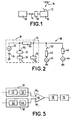
- the decoder receives the signals via an antenna 12 picking up the transmission supplied by a satellite 14.
- the reception of television transmissions, or of other data supplied by the satellite 14, is subject to authorization which is communicated via a telephone line 16.
- This telephone line 16 provides interactivity between the programmes received and the user; the line puts a centre 18 in contact with the decoder 10 via a modem 20.
- the link between the decoder 10 and the authorization centre 18 is formed in both directions.
- the decoder 10 can automatically request a link with the centre 18, for example in order to request a particular program, and, conversely, the centre 18 can automatically send information to the decoder 10, in order to give a reception authorization, for example.
- the telephone line 16 is used at the same time for other applications, such as the usual telephone communications or faxes, it is necessary for the automatic communication between the centre 18 and the decoder 10 not to disturb the operation of the subscriber's telephone handsets or other appliance.
- a detector of the busy state or the acquisition of the telephone line is provided, as is a means for breaking off the communication between the decoder 10 and the centre 18 when another use of the line 16 is requested, or the decoder 10 is prevented from acquiring or requesting the line when the line is busy.
- the invention relates to a means for detecting the busy state or acquisition of a line by the modem 20.
- the modem 20 includes an LF generator 22, a DC current source 24 which, in this example, has a voltage of 2.5 V.
- the negative terminal of this source 24 is connected to earth.
- the terminal of the low-frequency generator 22 which is opposite the one connected to the source 24 is linked, on the one hand, to a load or transfer impedance 26, of value Z m and, on the other hand, to a probe 30 via a divider element 32.
- the probe 30 is intended to measure the level of the LF signal produced on sending by the modem 20. This signal is, conventionally, denoted T x .
- the input/output 34 (called “input” or “output” below) of the modem 20 is connected to the terminal of the impedance 26 which is opposite the generator 22.
- the voltage at this input/output that is to say the potential difference (produced by the generator 22) between the terminal 34 and earth is detected by a probe 36.
- a signal R x At the terminals of the probe 36 appears a signal R x which is a function of the impedance of the circuits 38 connected to the modem.
- circuits 38 comprise, on the one hand, one (or more) subscriber's telephone generator(s) 40 which exhibit(s) an impedance 42 of value Z t and, on the other hand, the LF generator of the telephone line 44 exhibiting an impedance 46 of value Z 1 .
- the telephone instrument of impedance Z t , is linked to the line 50 via a switch 52.
- This switch 52 is open when the subscriber is not using his line and is closed when he is using his telephone line.
- the comparison between the signals supplied by the probes 30 and 36 makes it possible to determine reliably - as explained below - whether the line is free or busy with an appliance other than the modem, that is to say whether the switch 52 is open or closed, whatever the type of line.
- the ratio r 1 has a value of 0.5 and the ratio r 2 has a value of 0.33 (one third).
- the signal R x when the line is busy (switch 52 closed), exhibits a value which is significantly lower than its value when the line is free.
- the measurements on the probes 30 and 36 are preferably made by integration over a relatively lengthy period.
- the division factor r of the divider element 32 is chosen in such a way that the signal T x delivered by the probe 30 is always higher than the signal R x supplied by the probe 36 when the switch 52 is closed. Moreover, this factor r should be such that the signal T x is always lower than the signal R x when the switch 52 is open.
- the factor r should thus lie between r 2 and r 1 .
- the factor r should be chosen in such a way as to take account of all the possible values of Z 1 and Z t , that is to say of the known dispersions on these values.
- the impedance of the telephone instrument 42 exhibited a value of 600 ⁇ . It has been noted that the precision on this value is generally ⁇ 50 ⁇ .
- the values Z 1 of line impedance 46 depend, on the one hand, on the length of the line, and, on the other hand, on the signal supplied by the modem, and thus on the modulation, since the impedance depends on the frequency.
- the suffix "min” or “max” means minimum value or maximum value for the parameter to which it is allocated and D, in decibels, is the ratio existing between, on the one hand, the level of the signal delivered by the probe 36 when the switch 52 is open and, on the other hand, the level of this signal when the switch 52 is closed.
- the difference is a minimum of 2.2 dB, which is sufficient for carrying out easily measurable discrimination.
- the reduction in spectrum is, obviously, achieved by filtering.
- This filtering is carried out, for example, by programming the data processor located in the modem or the decoder.
- F 2 rms is the square of the rms value of the signal sampled over a period Ts.
- the signal F 2 rms is the image of the average power of the signal on the probe 36.
- y(n) is the power integrated at stage n
- x(n) is the signal R x at stage n
- Td is a multiple of the sampling period and thus corresponds to a measurement window.
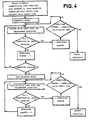
- Figure 3 is a flow chart (forming part of the description) representing the various stages of the calculation corresponding to the equation above.
- Connection R x Level Expected means the level of R x which is expected during the connection
- Data Exchange R x Level Expected means the level of R x which is expected during the data exchange phase
- Connection Valid Detect Time means the validation time during the connection
- Exchange Valid Detect Time means the validation time in the course of data exchange.
- the validation times indicated above take the following values: 1 to 2 seconds for data exchange and a few hundreds of milliseconds for the connection attempt.
- Some modems have terminals making it possible to gain access to variables such as the average power at the input to the modem or the variable gain of a power amplifier with variable gain which determines the level of the input signal. These terminals can be used for the detection, and particularly for calculating the ratios r 1 and r 2 and/or calculating the impedances Z 1 and Z t .
- the modems using Rockwell components with references RC 2123 DPL, RC 2324 DPL, RC 144, RCV 144, RC 288, RCV 288, RC 56D and RC 336 D have outputs delivering the "average power" and "variable gain” variables.
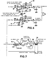
- the signal R x originating from the probe 36 is applied to the input of an amplifier circuit 60 which comprises, on the one hand, a peak detector 62 and, on the other hand, an offset device 64 supplying a reference voltage.
- the output of the circuit 60 is connected to the first input 66 1 of a comparator 66, the second input 66 2 of which is linked to the output of a circuit 70 the input of which receives the signal originating from the generator 22.
- This circuit 70 also includes a peak detector 72 and the divider element 32.
- the output of the comparator 66 is linked to one control input of a line-acquisition circuit 76 via a time delay circuit 78 for validating the minimum comparison time.
- the reference voltage fixed by the device 64 makes it possible, in the absence of detected energy, for there to be no erratic triggering of a detection.
- filters are arranged at the inputs of the devices 60 and 70 so as to let through only a limited band of frequencies, for example the sending band of V22bis modulation.
- This arrangement makes it possible to limit the dispersion on the impedance Z 1 as explained above.
- a bandpass filter for example, for the circuit 60, a capacitor 80 and a resistor 82 in series are provided, as well as a shunt capacitor 84.
- the peak detectors are implemented using operational amplifiers 90.
- a resistor 92 is provided, with a value chosen as a function of the dynamic range sought on the signal R.
- the divider element includes a resistor 94 which is located at the input of the corresponding operational amplifier 96.
- the two operational amplifiers 90 and 96 are linked via a resistor 98 the value of which fixes the initial offset between the two items of energy level information. This offset makes it possible to differentiate the AC signal information from the DC signal information so as to discard the voltage originating from the generator 24 ( Fig. 2 ).
- Figure 7 is a diagram which represents the energy levels of the R x and T x signals during establishment of communication and line acquisition by a telephone appliance in parallel with the modem.
- the curve 100 represents the R x signal and the curve 102 represents the T x signal.
- a first sequence 104 After the line has been acquired by the modem, the latter generates call pulses.
- This call phase 104 is followed by a connection sequence 106.
- connection sequence 106 When the connection is established (sequence 108) the energy levels are noticeably higher than in the course of the connection sequence.
- the invention applies in general to an appliance intended to be connected to a telephone line, particularly when this appliance has lowest priority by comparison with other appliances on the same line.
Landscapes
- Engineering & Computer Science (AREA)
- Signal Processing (AREA)
- Computer Networks & Wireless Communication (AREA)
- Telephonic Communication Services (AREA)
- Monitoring And Testing Of Exchanges (AREA)
- Telephone Function (AREA)
- Digital Transmission Methods That Use Modulated Carrier Waves (AREA)
Claims (10)
- Modem, der dafür vorgeschen ist, mit einer Telefonleitung verbunden zu werden, umfassend eine Vorrichtung zum Erkennen des Besetztzustandes oder der Anforderung einer Telefonleitung, dadurch gekennzeichnet, dass die Vorrichtung zum Erkennen ein Mittel zum Vergleichen (66) eines von einem ersten Messfühler (36) an dem Eingang (34) des Modems, der mit der Telefonleitung (38) verbunden ist, empfangenen Signals RX mit einem Bezugssignal TX, das von einem zweiten Messfühler (30) empfangen wird, enthält wobei das Bezugssignal von einem Niederfrequenzgenerator (22) bereitgestellt wird und durch ein Teilelement (32) mit einem Teilfaktor geteilt wird, der zwischen den Werten r1 und r2 liegt, sodass:
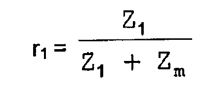

Dabei ist Z1 der Wert der Impedanz (46) der Telefonleitung, mit der der Modem verbunden ist, Zt der Wert der Impedanz (42) des Telefonapparats, der parallel zu dem Modem angeschlossen ist, und Zm der Wert der Lastimpedanz (26). - Modem gemäß Anspruch 1, dadurch gekennzeichnet, dass die Lastimpedanz in der Größenordnung von 600 Ω liegt, mit einer Genauigkeit dieses Werts von ± 50 Ohm.
- Modem gemäß Anspruch 1, dadurch gekennzeichnet, dass die Vorrichtung zum Erkennen ein Filterungsmittel enthält, mit dem das Spektrum der erkannten Signale begrenzt werden kann.
- Modem gemäß Anspruch 1, dadurch gekennzeichnet, dass die Vorrichtung zum Erkennen ein Mittel zum Bestimmen der durchschnittlichen Leistung des Signals, das unter den nominalen Nutzungsbedingungen des Modems an seinem Eingang/Ausgang bereitgestellt wird, sowie zum Speichern dieses Leistungswertes in einem Speicher enthält, wobei Mittel bereitgestellt werden, um die Dispersion auf den Leitungsimpedanzen zu beseitigen.
- Modem gemäß Anspruch 4, dadurch gekennzeichnet, dass die Messung der durchschnittlichen Leistung und die Speicherung im Speicher bei jedem Start des Modems erfolgen.
- Modem gemäß Anspruch 4, dadurch gekennzeichnet, dass die Erkennung ausgeführt wird, indem die durchschnittliche Leistung gemessen wird, vorzugsweise im Stichprobenverfahren.
- Modem gemäß Anspruch 4, dadurch gekennzeichnet, dass die Erkennung ausgeführt wird durch eine Messung der Verstärkung eines Leistungsverstärkers mit variablem Verstärkungsfaktor.
- Modem gemäß Anspruch 4, dadurch gekennzeichnet, dass die Erkennung kontinuierlich sowohl während der Verbindungsaufbau- als auch während der Datenaustauschphase ausgeführt wird.
- Modem gemäß Anspruch 1, dadurch gekennzeichnet, dass die Vorrichtung zum Erkennen ein Mittel enthält, um den Modem von der Leitung zu trennen oder um zu verhindern, dass er verbunden wird, wenn der Detektor ein Signal aussendet, welches anzeigt, dass die Leitung besetzt ist oder von einem parallel angeschlossenen Apparat angefordert wird.
- Modem gemäß Anspruch 1, dadurch gekennzeichnet, dass die Vorrichtung zum Erkennen ein Mittel enthält, um den Modem automatisch mit der Telefonleitung zu verbinden, wobei diese Verbindung automatisch unterbrochen wird, sobald die Vorrichtung zum Erkennen ein Besetztsignal oder ein Signal, dass die Leitung von einem anderen Apparat angefordert wurde, aussendet.
Applications Claiming Priority (2)
| Application Number | Priority Date | Filing Date | Title |
|---|---|---|---|
| FR9804848 | 1998-04-17 | ||
| FR9804848A FR2777727B1 (fr) | 1998-04-17 | 1998-04-17 | Modem comportant un dispositif de detection de l'occupation d'une ligne telephonique |
Publications (2)
| Publication Number | Publication Date |
|---|---|
| EP0951170A1 EP0951170A1 (de) | 1999-10-20 |
| EP0951170B1 true EP0951170B1 (de) | 2008-12-10 |
Family
ID=9525377
Family Applications (1)
| Application Number | Title | Priority Date | Filing Date |
|---|---|---|---|
| EP99400883A Expired - Lifetime EP0951170B1 (de) | 1998-04-17 | 1999-04-12 | Modem mit einer Vorrichtung zum Erkennung des Belegungszustands einer Fernsprechleitung |
Country Status (6)
| Country | Link |
|---|---|
| US (1) | US6292546B1 (de) |
| EP (1) | EP0951170B1 (de) |
| JP (1) | JPH11331430A (de) |
| CN (1) | CN1119011C (de) |
| DE (1) | DE69940039D1 (de) |
| FR (1) | FR2777727B1 (de) |
Families Citing this family (6)
| Publication number | Priority date | Publication date | Assignee | Title |
|---|---|---|---|---|
| FR2788184B1 (fr) * | 1998-12-31 | 2001-03-02 | Thomson Multimedia Sa | Methode, dispositif de detection de l'appel d'un telephone et modem comportant un tel dispositif |
| US6681011B1 (en) * | 2000-04-11 | 2004-01-20 | General Electric Company | Method and modem circuit using a dither signal for determining connection status of a phone line |
| KR100397681B1 (ko) * | 2001-07-27 | 2003-09-13 | 프롬투정보통신(주) | 전화기 인식을 위한 저주파 신호 발생장치 및 방법 |
| CN100442059C (zh) * | 2004-05-21 | 2008-12-10 | 特克特朗尼克公司 | 在电子测试仪器中用于将输入信道隔离的装置 |
| US7310521B2 (en) * | 2005-01-18 | 2007-12-18 | General Motors Corporation | Method to reduce modem call establishment time to a telematics unit |
| US8223958B2 (en) * | 2005-10-27 | 2012-07-17 | Hewlett-Packard Development Company, L.P. | Determining an active line |
Family Cites Families (6)
| Publication number | Priority date | Publication date | Assignee | Title |
|---|---|---|---|---|
| US4958371A (en) * | 1988-04-19 | 1990-09-18 | Control Data Corporation | Method and apparatus for determining when a telephone handset is off-hook |
| US5140631A (en) * | 1990-10-02 | 1992-08-18 | Intertex Data Ab | Apparatus and method for determining the state of a telephone line |
| US5506891A (en) * | 1993-07-06 | 1996-04-09 | Cirrus Logic, Inc. | Method and apparatus for detecting the connection status of an extension phone connected to a voice/fax/data modem |
| US5422939A (en) * | 1993-08-05 | 1995-06-06 | Schlumberger Industries, Inc. | Parallel off-hook detection for both line-available and phone pick-up detection |
| US6134321A (en) * | 1995-12-22 | 2000-10-17 | Thomas Licensing S.A. | Modem loop current detect system to detect an off-hook condition in an extension telephone |
| EP0868810B1 (de) * | 1995-12-22 | 2006-09-06 | Thomson Multimedia Inc. | Automatisches teilnehmerrückrufsystem |
-
1998
- 1998-04-17 FR FR9804848A patent/FR2777727B1/fr not_active Expired - Fee Related
-
1999
- 1999-04-12 EP EP99400883A patent/EP0951170B1/de not_active Expired - Lifetime
- 1999-04-12 DE DE69940039T patent/DE69940039D1/de not_active Expired - Lifetime
- 1999-04-13 US US09/290,624 patent/US6292546B1/en not_active Expired - Lifetime
- 1999-04-14 JP JP11106973A patent/JPH11331430A/ja active Pending
- 1999-04-16 CN CN99105794.5A patent/CN1119011C/zh not_active Expired - Fee Related
Also Published As
| Publication number | Publication date |
|---|---|
| DE69940039D1 (de) | 2009-01-22 |
| CN1240322A (zh) | 2000-01-05 |
| FR2777727A1 (fr) | 1999-10-22 |
| JPH11331430A (ja) | 1999-11-30 |
| CN1119011C (zh) | 2003-08-20 |
| FR2777727B1 (fr) | 2000-06-30 |
| EP0951170A1 (de) | 1999-10-20 |
| US6292546B1 (en) | 2001-09-18 |
Similar Documents
| Publication | Publication Date | Title |
|---|---|---|
| US6292052B1 (en) | Output amplifier for a discrete filter-less optical reference receiver | |
| US6668041B2 (en) | Single ended line probing in DSL system | |
| EP0398824B1 (de) | Numerischer Isolationsprüfer für ein elektrisches Netz | |
| EP0668677B1 (de) | Verfahren und Vorrichtung zur Bewertung des Systemsicherheitsspielraums eines digitalen Übertragungssystems | |
| EP0539017A2 (de) | Anpassungsfähige frequenzabhängige Kompensation für Telekommunikationskanäle | |
| US6392219B1 (en) | Discrete filter-less optical reference receiver and output amplifier | |
| US20040080323A1 (en) | Signal pre-processing for estimating attributes of a transmission line | |
| EP0951170B1 (de) | Modem mit einer Vorrichtung zum Erkennung des Belegungszustands einer Fernsprechleitung | |
| WO1995031865A1 (en) | Customer line tester | |
| US6781386B2 (en) | Method and device for measuring a line attenuation | |
| US20080310617A1 (en) | Transmission Links | |
| US7426262B2 (en) | Method and arrangement for loop test of a disturbed line | |
| WO1996025825B1 (en) | Method and structure for detecting a customer premises equipment alerting signal | |
| EP0547228B1 (de) | Verfahren zur messung des mittelwerts eines pulsförmigen signals | |
| EP0405593A2 (de) | Hochfrequenzmesseinrichtung mit verkabelter Messwerterfassung und Signal-Kompandierung | |
| US6473210B1 (en) | Method for measuring the performance of broadband dense wavelength division multiplexer (DWDM) using non-linear iterative algorithm | |
| JP4495238B2 (ja) | 通信伝送路の特性を推定するための方法、装置、およびコンピュータプログラム | |
| JP3185175B2 (ja) | シリアル・デジタル測定装置及びケーブル測定方法 | |
| JP3233675B2 (ja) | 接点情報の収集システム | |
| EP0965819B1 (de) | Schnittstellenschaltungsanordnung für piezoelektrischen Sensor | |
| AU745208B2 (en) | Remote testing of a communications line | |
| US7542562B1 (en) | Method for automatically adapting levels of signals exchanged in a communication network | |
| CA2122180C (en) | Automatic loss control circuit | |
| SU1035813A1 (ru) | Устройство контрол качества св зи с амплитудной и частотной манипул цией | |
| US20030202652A1 (en) | Characterization of telephone circuits |
Legal Events
| Date | Code | Title | Description |
|---|---|---|---|
| PUAI | Public reference made under article 153(3) epc to a published international application that has entered the european phase |
Free format text: ORIGINAL CODE: 0009012 |
|
| AK | Designated contracting states |
Kind code of ref document: A1 Designated state(s): DE FR GB IT |
|
| AX | Request for extension of the european patent |
Free format text: AL;LT;LV;MK;RO;SI |
|
| AKX | Designation fees paid | ||
| REG | Reference to a national code |
Ref country code: DE Ref legal event code: 8566 |
|
| RBV | Designated contracting states (corrected) |
Designated state(s): DE FR GB IT |
|
| 17P | Request for examination filed |
Effective date: 20000411 |
|
| 17Q | First examination report despatched |
Effective date: 20040504 |
|
| GRAP | Despatch of communication of intention to grant a patent |
Free format text: ORIGINAL CODE: EPIDOSNIGR1 |
|
| GRAS | Grant fee paid |
Free format text: ORIGINAL CODE: EPIDOSNIGR3 |
|
| GRAA | (expected) grant |
Free format text: ORIGINAL CODE: 0009210 |
|
| AK | Designated contracting states |
Kind code of ref document: B1 Designated state(s): DE FR GB IT |
|
| REG | Reference to a national code |
Ref country code: GB Ref legal event code: FG4D |
|
| REF | Corresponds to: |
Ref document number: 69940039 Country of ref document: DE Date of ref document: 20090122 Kind code of ref document: P |
|
| PLBE | No opposition filed within time limit |
Free format text: ORIGINAL CODE: 0009261 |
|
| STAA | Information on the status of an ep patent application or granted ep patent |
Free format text: STATUS: NO OPPOSITION FILED WITHIN TIME LIMIT |
|
| 26N | No opposition filed |
Effective date: 20090911 |
|
| PGFP | Annual fee paid to national office [announced via postgrant information from national office to epo] |
Ref country code: GB Payment date: 20130424 Year of fee payment: 15 Ref country code: DE Payment date: 20130419 Year of fee payment: 15 |
|
| PGFP | Annual fee paid to national office [announced via postgrant information from national office to epo] |
Ref country code: IT Payment date: 20130418 Year of fee payment: 15 Ref country code: FR Payment date: 20130503 Year of fee payment: 15 |
|
| REG | Reference to a national code |
Ref country code: DE Ref legal event code: R119 Ref document number: 69940039 Country of ref document: DE |
|
| GBPC | Gb: european patent ceased through non-payment of renewal fee |
Effective date: 20140412 |
|
| REG | Reference to a national code |
Ref country code: FR Ref legal event code: ST Effective date: 20141231 |
|
| REG | Reference to a national code |
Ref country code: DE Ref legal event code: R119 Ref document number: 69940039 Country of ref document: DE Effective date: 20141101 |
|
| PG25 | Lapsed in a contracting state [announced via postgrant information from national office to epo] |
Ref country code: DE Free format text: LAPSE BECAUSE OF NON-PAYMENT OF DUE FEES Effective date: 20141101 Ref country code: GB Free format text: LAPSE BECAUSE OF NON-PAYMENT OF DUE FEES Effective date: 20140412 |
|
| PG25 | Lapsed in a contracting state [announced via postgrant information from national office to epo] |
Ref country code: FR Free format text: LAPSE BECAUSE OF NON-PAYMENT OF DUE FEES Effective date: 20140430 |
|
| PG25 | Lapsed in a contracting state [announced via postgrant information from national office to epo] |
Ref country code: IT Free format text: LAPSE BECAUSE OF NON-PAYMENT OF DUE FEES Effective date: 20140412 |